Kramer VP-740 ProScale User manual

Kramer Electronics, Ltd.
USER MANUAL
Model:
VP
-
740
Presentation Scaler / Switcher

Contents
i
Contents
1
Introduction 1
2
Getting Started 1
3
Overview 2
4
Your VP-740 Presentation Scaler / Switcher 3
5
Installing the VP-740 Industrial Version on a Rack 7
6
Connecting the VP-740 Presentation Scaler / Switcher 8
6.1
Connecting a PC 10
7
Understanding the PIP Feature 11
7.1
Activating the PIP Feature 11
7.2
PIP Characteristics 12
7.3
Resizing the PIP 12
7.4
Moving the Position of the PIP 12
7.5
Locking and Unlocking the Front Panel 13
8
Operating the VP-740 via the OSD MENU Screen 14
8.1
The Image Tuning Menu Screen 15
8.1.1
The Gamma / Color Screen 16
8.1.2
TheGrayCorrection ScreenandAutoGain17
8.2
Controlling the Geometry 17
8.3
Selecting the Source 20
8.4
Configuring via the Utility Screens 21
8.4.1
Choosing the Video Setting Utility 21
8.4.2
Choosing the PC Data Utility 23
8.4.3
Choosing the PIP Settings Utility 24
8.4.4
Choosing the Seamless Switch Utility 26
8.4.5
Choosing the OSD Setting Utility 26
8.4.6
Choosing the Output Setting Utility 27
8.4.7
Verifying Configuration Details via the Information Screen 29
8.4.8
Choosing Factory Reset 29
8.4.9
Choosing Advanced 30
8.5
Saving and Loading 32
8.6
Operating via the Infra-red Remote Control Transmitter 34
9
Technical Specifications 35
10
VP-740 Communication Protocol 39

KRAMER: SIMPLE CREATIVE TECHNOLOGY
Contents
ii
Figures
Figure 1: VP-740 Presentation Scaler / Switcher Industrial Version 4
Figure 2: VP-740 Presentation Scaler / Switcher Home Version 5
Figure 3: Connecting the VP-740 Rear Panel 9
Figure 4: Connecting the PC 10
Figure 5: OSD PIP Status 12
Figure 6: Locking / Unlocking the Front Panel 13
Figure 7: OSD Screen Icons 14
Figure 8: First OSD Screen: the “Image Tuning” Menu Screen 15
Figure 9: Gamma / Color Screen 16
Figure 10: Color Manager Screen 16
Figure 11: Gray Correction Screen 17
Figure 12: Geometry Screen 17
Figure 13: Geometry – Zoom Setting Screen 18
Figure 14: Geometry – Zoom Ratio Screen 18
Figure 15: Geometry Aspect Ratio Screen 19
Figure 16: Geometry Aspect Ratio Letterbox Pan Screen 19
Figure 17: Geometry Aspect Ratio Native Screen 19
Figure 18: Geometry Aspect Ratio 4:3 Output Shift Screen 20
Figure 19: Geometry Aspect Ratio User Define Screen 20
Figure 20: Source Selection Screen 21
Figure 21: Video Setting Utility Screen (Composite or s-Video Source) 21
Figure 22: Video Setting Utility Screen 22
Figure 23: Video Standard Video Setting Utility Screen 22
Figure 24: PC Data Utility Screen (Component, VGA, DVI or HDTV Source) 23
Figure 25: PC Data Utility Screen 23
Figure 26: PC Data Utility Color Formats Screen 24
Figure 27: PIP Setting Utility On/Off Screen 24
Figure 28: PIP Source Setting Utility Screen 25
Figure 29: PIP Size Setting Utility Screen 25
Figure 30: Seamless Switch Utility Screen 26
Figure 31: OSD Setting Utility 26
Figure 32: Output Setting Resolution Utility Screen 27
Figure 33: OSD Output Status 27
Figure 34: Output Setting Refresh Rate Utility Screen 28
Figure 35: Output Setting User Mode Setting Utility Screen 28
Figure 36: Information Screen 29
Figure 37: Factory Reset Screen 29
Figure 38: Advanced Screen 30
Figure 39: Advanced Screen – Lock Options 30
Figure 40: Advanced Screen –Mode Define 31
Figure 41: Save and Load Screen 32
Figure 42: Save Screen 32
Figure 43: Load Screen 33
Figure 44: Remote Transmitter 34

Contents
iii
Tables
Table 1: Front Panel VP-740 Presentation Scaler / Switcher Features 5
Table 2: Rear Panel VP-740 Presentation Scaler / Switcher Features 6
Table 3: User Mode Setting Definitions 28
Table 4: Mode Define Features 31
Table 5: VP-740 Remote Transmitter Functions 34
Table 6: Technical Specifications of the VP-740 35
Table 7: Technical Specifications of the VP-740 (Input Signal – VGA) 36
Table 8: Technical Specifications of the VP-740 (Input Signal – DVI) 37
Table 9: Technical Specifications of the VP-740 (Input Signal – HDTV) 37
Table 10: Technical Specifications of the VP-740 (Output Signal – RGB / DVI Mode) 38
Table 11: RS-232 Protocol 39

Introduction
1
1 Introduction
Welcome to Kramer Electronics (since 1981): a world of unique, creative and
affordable solutions to the infinite range of problems that confront the video,
audio and presentation professional on a daily basis. In recent years, we have
redesigned and upgraded most of our line, making the best even better! Our
500-plus different models now appear in 8 Groups
1
, which are clearly defined
by function.
Congratulations on purchasing your Kramer VP-740 Presentation Scaler /
Switcher, which is ideal for the following typical applications:
Home cinema central visual switcher
Presentation
Educational, industrial, points of sale, churches and other large audience
applications
The package includes the following items:
VP-740 Presentation Scaler / Switcher
Power cord
2
, Null-modem adapter and infra-red remote control transmitter
This user manual
3
2 Getting Started
We recommend that you:
Unpack the equipment carefully and save the original box and packaging
materials for possible future shipment
Review the contents of this user manual
Use Kramer high performance high resolution cables
4
1 GROUP 1: Distribution Amplifiers; GROUP 2: Video and Audio Switchers, Matrix Switchers and Controllers; GROUP 3:
Video, Audio, VGA/XGA Processors; GROUP 4: Interfaces and Sync Processors; GROUP 5: Twisted Pair Interfaces;
GROUP 6: Accessories and Rack Adapters; GROUP 7: Scan Converters and Scalers; and GROUP 8: Cables and Connectors
2 We recommend that you use only the power cord that is supplied with this machine
3 Download up-to-date Kramer user manuals from the Internet at this URL: http://www.kramerelectronics.com
4 The complete list of Kramer cables is on our Web site at http://www.kramerelectronics.com

KRAMER: SIMPLE CREATIVE TECHNOLOGY
Overview
2
3 Overview
The VP-740 Presentation Scaler / Switcher is a high quality graphics and video
scaler, scaling any input format and resolution to a user-defined output resolution.
In particular, the VP-740 Presentation Scaler / Switcher:
Switches between the sources using FTB™ (Fade-Thru-Black)
technology, outputting an extremely high quality image even from a low
quality source
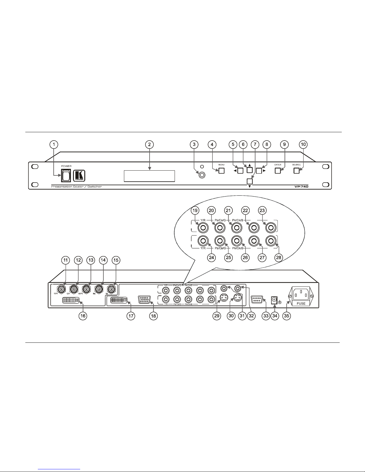
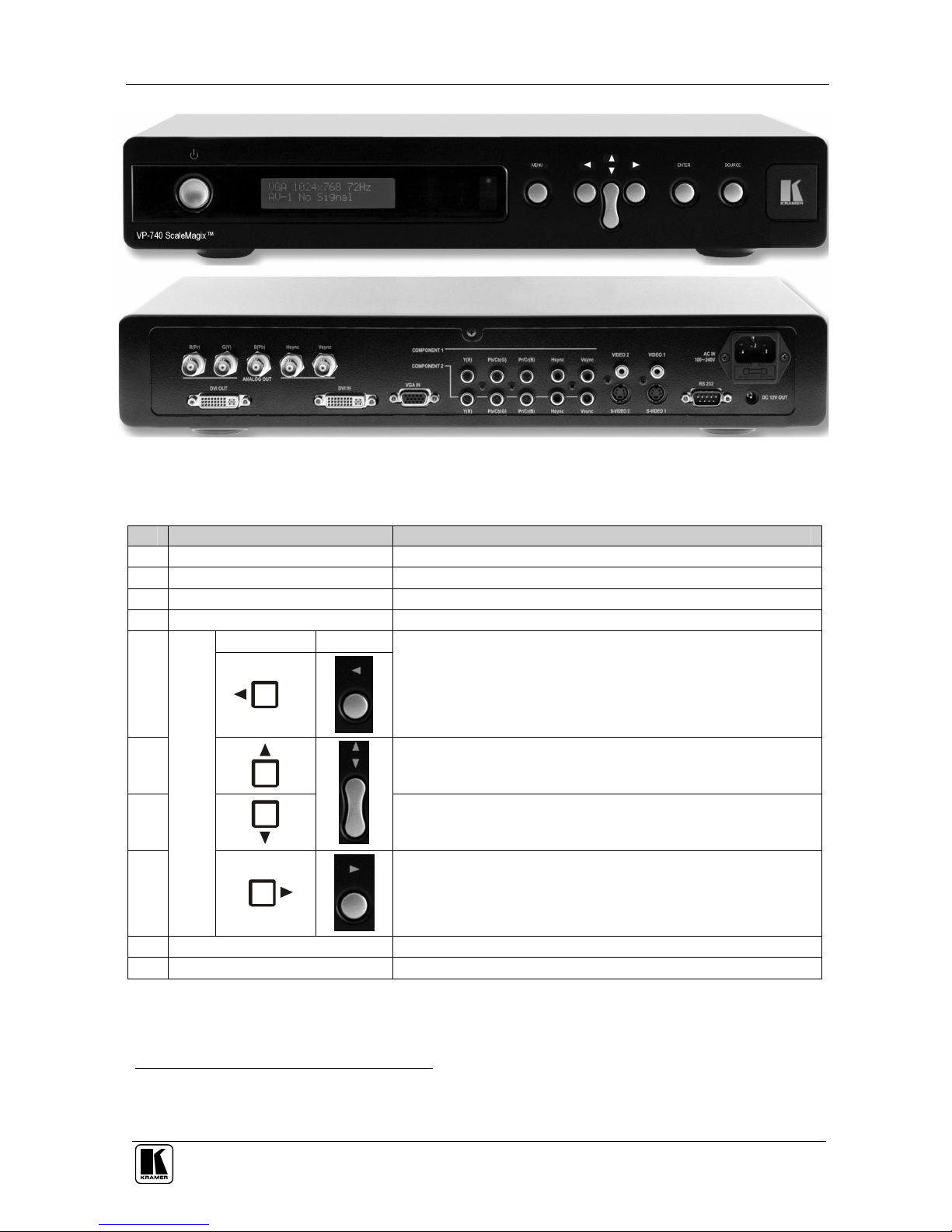
Features 2xCV, 2xY/C, 2xYUV, 1xVGA, 1xDVI-D inputs, and RGBHV,
Y, Pb, Pr, and DVI outputs (the DVI inputs/outputs do not support
HDCP
1
)
Supports all popular graphics and HDTV output resolutions: 480p
(720x483), 576p (720x576), 720p (1280x720), and 1080i (1920x540)
With its aspect ratio and film-related enhancements, is the perfect
companion to any Home Cinema set up
With the unique Kramer K-IIT™ (image insertion technology), provides a
picture-in-picture facility for graphics-into-video and vice versa, as well
as video-into-progressive scan component and vice versa
Uses a universal power supply
2
– 100-240 VAC with automatic voltage
selection
Includes a rear panel 12VDC OUT power connector that can supply
500mA to any machine with a 12VDC power input
Can output to these resolutions: VGA (640x480), SVGA (800x600), XGA
(1024x768), SXGA (1280x1024), UXGA (1600x1200), 720x483,
1280x720, 1920x1080i, 852x480, 1366x768, 1365x1024, 1400x1050,
480p, 576p, 720p, 1080i or User Define
3
In addition, the VP-740:
Incorporates a unique graphics-scaling engine with image enhancement
algorithms, which are built into the firmware
Is specifically designed to improve video quality by reducing chroma noise
Digitally reprocesses the signal to correct mastering errors, and
regenerates the video at a chosen line and pixel rate format, providing, for
example, native-resolution video for LCD, DLP and Plasma displays
1 High-Bandwidth Digital Content Protection
2 We recommend that you use only the power cord that is supplied with this machine
3 The user definable output mode is recommended for advanced users only – non-standard settings may not be recognized by
the display device

Your VP-740 Presentation Scaler / Switcher
3
Includes a built-in Picture-in-Picture inserter, letting you insert a video
source into a graphics background or vice versa, allowing the user to size
and position the shrunken inserted image anywhere on the screen
Includes an OSD (on-screen display) that superimposes a menu on the
screen for making the adjustments. The OSD itself can be adjusted—the
OSD size and position, the time out, and whether the OSD status label is
displayed
Includes a front panel SOURCE button that scans the inputs until it
locates an active source
Includes a front panel lock that can be programmed via the OSD menu
1
Offers high quality de-interlacing 3:2/2:2 pull down
2
Can provide non-linear scaling for 4:3, 16:9 transformation
Supports firmware upgrade via RS-232
Includes non-volatile memory that retains the last setting, after switching
the power off
Includes a front panel LCD
Control the VP-740:
From the front panel OSD control buttons
Remotely, from the infra-red remote control transmitter
Remotely, via RS-232
To achieve the best performance:
Connect only good quality connection cables, thus avoiding interference,
deterioration in signal quality due to poor matching, and elevated noise-
levels (often associated with low quality cables)
Avoid interference from neighboring electrical appliances and position
your Kramer VP-740 away from moisture, excessive sunlight and dust
4 Your VP-740 Presentation Scaler / Switcher
The VP-740 Presentation Scaler / Switcher comes in two versions—an
industrial version (illustrated in Figure 1) and an elegant home version
(illustrated in Figure 2)—both are defined in Table 1 and Table 2.
1 See section 8.4.9
2 Accommodates the frame-rate of a converted movie (24 frames per second) to video frequencies (25 frames per second
(PAL); 30 frames per second (NTSC)

KRAMER: SIMPLE CREATIVE TECHNOLOGY
Your VP-740 Presentation Scaler / Switcher
4
IR
DVI
DVI VGA
OUTPUTS
INPUTS
YC 2
YC 1
CV 2
CV 1
RS-232
12 VDC
OUT
100-240 VAC
50/60 Hz
+
Hs
Vs
Comp 1
Comp 2
Hs Vs
Hs
Vs
Comp 1
Comp 2
Hs Vs
Figure 1: VP-740 Presentation Scaler / Switcher Industrial Version

Your VP-740 Presentation Scaler / Switcher
5
Figure 2: VP-740 Presentation Scaler / Switcher Home Version
Table 1: Front Panel VP-740 Presentation Scaler / Switcher Features
# Feature Function
1 POWER Switch Illuminated switch supplying power to the unit
2 STATUS Display Displays the status (see section 8)
3 IR Receiver / LED Red when the unit will accept IR remote commands
4 MENU Button Displays the OSD Menu screen
1
and locks/unlocks the front panel
Industrial Home
5
Decreases the range by one step in the OSD screen
6
Moves up one step (in the same level) in the OSD screen
7
Moves down one step (in the same level) in the OSD screen
8
Scroll Buttons on Version:
Increases the range by one step in the OSD screen
9 ENTER Button Moves to the next level in the OSD screen
10 SOURCE Button Scans the inputs until it locates an active source(s)
2
1 Or moves to the previous level in the OSD screen
2 AV-1, AV-2, YC-1, YC-2, Comp 1, Comp 2, VGA, or DVI

KRAMER: SIMPLE CREATIVE TECHNOLOGY
Your VP-740 Presentation Scaler / Switcher
6
Table 2: Rear Panel VP-740 Presentation Scaler / Switcher Features
# Feature Function
11 R/Pr BNC Connector
12 G/Y BNC Connector
13 B/Pb BNC Connector
14 Hs
2
BNC Connector
15 Vs
2
BNC Connector
Connect to the RGBHV acceptor (or the component video acceptor
1
)
16
OUTPUTS
DVI Connector
3
Connects to the DVI
4
graphics acceptor
17 DVI INPUTS Connector
3
Connects to the DVI
4
graphics source
18 VGA INPUTS HD15 Connector Connects to the VGA (analog interface) graphics source
19 Y/R RCA Connector Connects to the RGBHV source 1 or component video source 1
20 P
B
/C
B
/G RCA Connector Connects to the RGBHV source 1 or component video source 1
21 P
R
/C
R
/B RCA Connector Connects to the RGBHV source 1 or component video source 1
22 Hs RCA Connector Connects to the RGBHV source 1
23
Comp 1
INPUTS
Vs RCA Connector Connects to the RGBHV source 1
24 Y/R RCA Connector Connects to the RGBHV source 2 or component video source 2
25 P
B
/C
B
/G RCA Connector Connects to the RGBHV source 2 or component video source 2
26 P
R
/C
R
/B RCA Connector Connects to the RGBHV source 2 or component video source 2
27 Hs RCA Connector Connects to the RGBHV source 2
28
Comp 2
INPUTS
Vs RCA Connector Connects to the RGBHV source 2
29 YC 2 INPUTS 4p Connector Connects to the s-Video source 1
30 YC 1 INPUTS 4p Connector Connects to the s-Video source 2
31 CV 2 INPUTS RCA Connector Connects to the composite video source 1
32 CV 1 INPUTS RCA Connector Connects to the composite video source 2
33 RS-232 DB 9 Connector Connects to PC or Serial Controller
34 12V DC OUT +12V DC connector for powering another unit
35 Power Connector with FUSE AC connector enabling power supply to the unit
1 Via the R/Pr, G/Y and B/Pb connectors
2 For RGBS applications, one of the sync channels (Horizontal or Vertical) may be used for the S channel
3 Not HDCP compliant
4 Note that only the digital signal (DVI-D) is available on the DVI (digital video interface) connector

Installing the VP-740 Industrial Version on a Rack
7
5 Installing the VP-740 Industrial Version on a Rack
This section describes what to do before installing on a rack and how to rack
mount.
Before Installing on a Rack
Before installing on a rack, be sure that the environment is
within the recommended range:
Operating temperature range +5 to +45 Deg. Centigrade
Operating humidity range 5 to 65 % RHL, non-condensing
Storage temperature range -20 to +70 Deg. Centigrade
Storage humidity range 5 to 95% RHL, non-condensing
CAUTION!!
When installing on a 19" rack, avoid hazards by taking
care that:
1
It is located within the recommended environmental
conditions, as the operating ambient temperature of a
closed or multi unit rack assembly may exceed the room
ambient temperature.
2
Once rack mounted, enough air will still flow around the
machine.
3
The machine is placed straight in the correct horizontal
position.
4
You do not overload the circuit(s). When connecting the
machine to the supply circuit, overloading the circuits
might have a detrimental effect on overcurrent
protection and supply wiring. Refer to the appropriate
nameplate ratings for information. For example, for fuse
replacement, see the value printed on the product label.
5
The machine is earthed (grounded) in a reliable way and
is connected only to an electricity socket with grounding.
Pay particular attention to supply connections other than
direct connections to the branch circuit (for example, the
use of power strips), and that you use only the power cord
that is supplied with the machine.
How to Rack Mount
To rack-mount the machine:
1
Attach both ear brackets to the
machine. To do so, remove the
screws from each side of the
machine (3 on each side), and
replace those screws through
the ear brackets.
2
Place the ears of the machine
against the rack rails, and insert
the proper screws (not provided)
through each of the four holes in
the rack ears.
Note that:
In some models, the front panel
may feature built-in rack ears
Detachable rack ears can be
removed for desktop use
Always mount the machine in the
rack before you attach any cables or
connect the machine to the power
If you are using a Kramer rack
adapter kit (for a machine that is not
19"), see the Rack Adapters user
manual for installation instructions
(you can download it at:
http://www.kramerelectronics.com)

KRAMER: SIMPLE CREATIVE TECHNOLOGY
Connecting the VP-740 Presentation Scaler / Switcher
8
6 Connecting the VP-740 Presentation Scaler / Switcher
Using the VP-740 you can select any one of the 8 inputs and scale that input
to the output at the desired resolution.
To connect the VP-740, as the example in Figure 3 illustrates, do the
following
1
:
1. Connect two composite video sources (for example, composite video
player 1 and composite video player 2), to the CV 1 and CV 2 INPUT
RCA connectors respectively.
2. Connect two s-Video sources (for example, s-Video player 1 and s-Video
player 2), to the YC 1 and YC 2 INPUT 4p connectors respectively.
3. Connect an RGB or component video
2
source to the three Comp 2 INPUT
RCA connectors
3
Y/R, P
B
/C
B
/G, and P
R
/C
R
/B. For example:
An RGB camera to Y/R, P
B
/C
B
/G, P
R
/C
R
/B OR
A component video player to Y/R, P
B
/C
B
/G, P
R
/C
R
/B
4. Connect a computer graphics source to the VGA INPUT HD15 connector.
5. Connect a DVI (digital video interface) graphics source, to the DVI
INPUT connector (not HDCP compliant).
6. Connect the five BNC OUTPUT connectors: R/Pr, G/Y, B/Pb, Hs, and Vs,
to a video acceptor (for example, a plasma display).
7. Connect the DVI OUTPUT connector (not HDCP compliant) to a video
acceptor (for example, a projector).
8. Connect the power cord
4
(not illustrated in Figure 3).
9. Connect a DC power plug (optional) from another Kramer unit
5
(that
requires a 12VDC power input) to the 12VDC OUT connector.
10. Connect a PC (optional), as section 6.1 describes.
1 Switch OFF the power on each device before connecting it to your VP-740. After connecting your VP-740, switch on its
power and then switch on the power on each device
2 Y/R, Pb/Cb/G, Pr/Cr/B is also known as Y, B-Y, R-Y, or YUV or Y, Pb, Pr
3 The Comp 1 and the Comp 2 INPUTS RCA connectors are interchangeable. You can connect two RGBHV sources, an
RGBHV source to Comp 2 as well as to Comp 1; or two component (or RGB) sources, to Comp 1 as well as to Comp 2
4 We recommend that you use only the power cord that is supplied with this machine
5 For example, the Kramer FC-15

Connecting the VP-740 Presentation Scaler / Switcher
9
Projector
DVI Graphics
Source
Computer Graphics
Source
Camera (RGB)
Source
Plasma
Display
RS-232
Figure 3: Connecting the VP-740 Rear Panel

KRAMER: SIMPLE CREATIVE TECHNOLOGY
Connecting the VP-740 Presentation Scaler / Switcher
10
6.1 Connecting a PC
You can connect a PC (or other controller) to the VP-740 via the RS-232 port
for remote control, and for upgrading the firmware.
To connect a PC to a VP-740 unit, using the Null-modem adapter provided
with the machine (recommended):
Connect the RS-232 DB9 rear panel port on the VP-740 unit to the
Null-modem adapter and connect the Null-modem adapter with a 9-wire
flat cable to the RS-232 DB9 port on your PC
To connect a PC to a VP-740 unit, without using a Null-modem adapter:
Connect the RS-232 DB9 port on your PC to the RS-232 DB9 rear panel
port on the VP-740 unit, forming a cross-connection
1
, as Figure 4
illustrates
D
B
9
(
ToPresentation
Scaler
/
Switcher
)
DB9(FromPC
)
Figure 4: Connecting the PC
1 Also known as a Null-modem connection

Understanding the PIP Feature
11
7 Understanding the PIP Feature
The Picture-in-Picture inserter (PIP) is used for the simultaneous display of
video and graphic sources, and lets you display:
An inserted video source
1
PIP over a graphic source
2
An inserted graphic source
2
PIP over a video source
1
Your Presentation Scaler / Switcher automatically recognizes and displays
only the relevant sources, as the following two examples illustrate:
Choosing the AV 1 PIP source when the VGA input is selected, will insert
the composite video source over the VGA graphic displayed on the
screen. You can choose a component, YC 1, YC 2 or AV 2 PIP source
3
(instead of the AV 1). You cannot choose VGA or DVI
4
Choosing the VGA PIP source when the AV 1 input is selected, will insert
the VGA graphic source over the composite video displayed on the
screen. You can choose a VGA or DVI PIP source
3
(instead of the VGA).
You cannot choose AV 2, YC 1, or YC 2
5
7.1 Activating the PIP Feature
To turn ON the PIP, do one of the following:
Switch on the PIP functionality via the OSD Menu (see Figure 27)
Press the PIP key on the remote control transmitter (see Figure 44)
When the Label is ON
6
(see Figure 31), the PIP is enclosed by an orange
frame, and the OSD PIP status appears superimposed over the top right corner
of the screen for a few seconds, as Figure 5 illustrates. After a few seconds
7
,
the orange frame and the OSD PIP status automatically disappear
8
.
Activating the PIP subsequently cycles between the PIP with the orange
frame and no PIP.
1 That is, composite, s-Video or component video (interlaced)
2 That is, DVI, VGA or progressive component video
3 As long as it is connected and switched on. Otherwise, choosing it will display a blank screen
4 As these are graphics sources and you cannot insert a graphics PIP over a graphics source
5 As these are video sources and you cannot insert a video PIP over a video source
6 The information prompt will appear while you change the source or adjust the image. For example, you can resize the PIP
via the infra-red remote control transmitter (see section 7.3)
7 By default, 20 seconds. But you can reset the timeout (from 3 to 60 seconds)
8 Trying to activate the PIP again while the PIP is still enclosed by an orange frame deactivates the PIP

KRAMER: SIMPLE CREATIVE TECHNOLOGY
Understanding the PIP Feature
12
Figure 5: OSD PIP Status
7.2 PIP Characteristics
You can determine the following PIP characteristics:
PIP Source
PIP Size (1/4, 1/9, 1/16, 1/25, Split or User Define)
Horizontal and Vertical position, placing it anywhere on the screen
7.3 Resizing the PIP
To resize the PIP (1/4, 1/9, 1/16, 1/25, Split or User Define):
When the Label is ON and the PIP is enclosed by an orange frame, press
the Up and/or Down DIRECTION keys on the infra-red remote control
transmitter or the UP and/or DOWN front panel scroll buttons
Use the OSD Menu buttons
7.4 Moving the Position of the PIP
To move the location of the PIP:
When the the orange frame and the OSD PIP status automatically
disappear
1
, press the Up, Down, Left and/or Right DIRECTION keys on
the infra-red remote control transmitter or the UP, DOWN, LEFT and/or
RIGHT front panel scroll buttons
Adjust
2
the H-Position and/or V-Position in the PIP Utility Settings OSD
Menu (see section 8.4.3), using the remote control transmitter or the front
panel OSD buttons
1 Label and frame disappear according to the Time Out Setting in the utilities Menu (see section 8.4.5)
2 Adjustment range is between –32 and +32 (default is –31)

Understanding the PIP Feature
13
7.5 Locking and Unlocking the Front Panel
You can lock the front panel
1
and control from the infra-red remote control
transmitter to safeguard the settings on the VP-740.
To lock the front panel completely (none of the buttons are active):
Press and hold the MENU front panel OSD button or the MENU key on
the infra-red remote control transmitter for a few seconds, until the Key
Lock On OSD status appears superimposed over the top right corner of
the screen for a few seconds
2
, as Figure 6 illustrates
Figure 6: Locking / Unlocking the Front Panel
You can also:
Lock the front panel, but keep the SOURCE button on the front panel and
the source selection buttons on the IR control transmitter active while
the remaining machine functions are locked (see section 8.4.9)
Keep the machine locked
3
after cycling the power (see section 8.4.9)
To unlock the front panel (releasing the protection mechanism):
Press and hold the MENU front panel OSD button or the MENU key on
the infra-red remote control transmitter for a few seconds, until the Key
Lock Off OSD status appears superimposed over the top right corner of
the screen for a few seconds
2
1 However, operation via RS-232 serial commands (remote controller or PC) is still available
2 By default, 20 seconds. But you can reset the timeout (from 3 to 60 seconds)
3 That is the front panel and the IR control transmitter remain locked

KRAMER: SIMPLE CREATIVE TECHNOLOGY
Operating the VP-740 via the OSD MENU Screen
14
8 Operating the VP-740 via the OSD MENU Screen
You can control the Presentation Scaler / Switcher from the:
Front panel OSD MENU and ENTER control buttons
Front panel OSD Scroll buttons:
Industrial
Version:
Home
Version:
Infra-red remote control transmitter MENU key and DIRECTION keys
(see section 8.6)
RS-232 remote control
The VP-740 also includes a front panel SOURCE button that scans the inputs
(AV-1, AV-2, YC-1, YC-2, Comp 1, Comp 2, VGA, and DVI) until it locates
an active source.
You can switch seamlessly
1
between each input
2
that is connected to a source,
by pressing the front panel SOURCE button. The OSD status appears
superimposed over the top right corner of the screen for a few seconds. Each
of the five OSD screens has its distinctive icon
3
, which is highlighted orange
when selected
4
(defined in Figure 7). In addition, the appropriate setting is
also displayed on the front panel STATUS display (for example, “Menu”
followed by “Image Tuning” on the line below, when the Image Tuning OSD
screen is selected).
Image Tuning
Geometry
Source Selection
Utility
Save and Load
Figure 7: OSD Screen Icons
1 For glitchless transitions between inputs
2 To set the image transition speed (fast, safe or moderate), see section 8.4.4
3 Each icon represents a Level 1 function. In addition to Level 1, the OSD structure includes Level 2 (a subset of level 1),
Level 3 (a subset of level 2), Level 4 (a subset of level 3)
4 In addition the name of the selected OSD screen appears in the top left. For example, “Image Tuning” in Figure 8

Operating the VP-740 via the OSD MENU Screen
15
Use the OSD Menu as follows:
Press the MENU front panel OSD button or the MENU key on the remote
control transmitter (see Figure 44) to display the first OSD screen
Press the MENU front panel OSD button or the MENU key on the
infra-red remote control transmitter (see Figure 44), to move to the
previous level in the OSD screen (Esc.)
Press the up or down arrow buttons to select the menu icons and press
ENTER to confirm the selection
Use the right and left arrow buttons to increase and decrease the
numerical rates (where relevant)
8.1 The Image Tuning Menu Screen
The “Image Tuning” menu screen (see Figure 8) lets you adjust the
brightness
1
, contrast
1
, saturation
1
, hue
1
and sharpness
2
.
Figure 8: First OSD Screen: the “Image Tuning” Menu Screen
1 Adjustment range is between –32 and +32 (default is 0)
2 Adjustment range is between –8 and +8 (default is 0)

KRAMER: SIMPLE CREATIVE TECHNOLOGY
Operating the VP-740 via the OSD MENU Screen
16
8.1.1 The Gamma / Color Screen
Figure 9 illustrates the Gamma
1
/ Color Screen
1
.
Figure 9: Gamma / Color Screen
Choosing Color Manager illustrated in Figure 9, lets you adjust the red, green,
blue and yellow (see Figure 10).
Figure 10: Color Manager Screen
1 Adjustment range is between –10 and +10 (default is 0)
Other manuals for VP-740 ProScale
2
Table of contents
Other Kramer Media Converter manuals

Kramer
Kramer VP-501N User manual

Kramer
Kramer 810 User manual

Kramer
Kramer VP-427H2 User manual

Kramer
Kramer VM-28H User manual

Kramer
Kramer TOOLS FC-47 User manual

Kramer
Kramer VA-256P User manual

Kramer
Kramer VM-2DVI User manual

Kramer
Kramer VP-426C User manual

Kramer
Kramer VP-435 User manual

Kramer
Kramer VM-2DH User manual

Kramer
Kramer FC-42 User manual

Kramer
Kramer VP-792 User manual

Kramer
Kramer VM-3A User manual

Kramer
Kramer VP-420 User manual

Kramer
Kramer DigiTOOLS 6410N User manual

Kramer
Kramer FC-69 User manual

Kramer
Kramer VM-2HDCPxl User manual

Kramer
Kramer VP-472 User manual

Kramer
Kramer FC-331 User manual

Kramer
Kramer VM-4HC User manual