manuals.online logo
Brands
  1. Home
  2. •
  3. Brands
  4. •
  5. Kramer
  6. •
  7. Media Converter
  8. •
  9. Kramer VW-9 User manual

Kramer VW-9 User manual

Other manuals for VW-9

1

Other Kramer Media Converter manuals

Kramer WP-DEC7 User manual

Kramer

Kramer WP-DEC7 User manual

Kramer FC-42 User manual

Kramer

Kramer FC-42 User manual

Kramer VP-440H2 User manual

Kramer

Kramer VP-440H2 User manual

Kramer DigiTOOLS 7508 User manual

Kramer

Kramer DigiTOOLS 7508 User manual

Kramer VP-510 User manual

Kramer

Kramer VP-510 User manual

Kramer VP-481 User manual

Kramer

Kramer VP-481 User manual

Kramer VP-721DS User manual

Kramer

Kramer VP-721DS User manual

Kramer PT-871/2xr-KIT User manual

Kramer

Kramer PT-871/2xr-KIT User manual

Kramer VM-50AN User manual

Kramer

Kramer VM-50AN User manual

Kramer 810 User manual

Kramer

Kramer 810 User manual

Kramer FC-49 User manual

Kramer

Kramer FC-49 User manual

Kramer KDS-EN7 User manual

Kramer

Kramer KDS-EN7 User manual

Kramer VA-11 User manual

Kramer

Kramer VA-11 User manual

Kramer VM-3UHD User manual

Kramer

Kramer VM-3UHD User manual

Kramer VM-100CA User manual

Kramer

Kramer VM-100CA User manual

Kramer 482 User manual

Kramer

Kramer 482 User manual

Kramer VP-429H2 User manual

Kramer

Kramer VP-429H2 User manual

Kramer VP-2XL User manual

Kramer

Kramer VP-2XL User manual

Kramer KDS-SW3-EN7 User manual

Kramer

Kramer KDS-SW3-EN7 User manual

Kramer VP-435 User manual

Kramer

Kramer VP-435 User manual

Kramer VP-420 User manual

Kramer

Kramer VP-420 User manual

Kramer VA-680D User manual

Kramer

Kramer VA-680D User manual

Kramer VM-4Hxl User manual

Kramer

Kramer VM-4Hxl User manual

Kramer FC-14 User manual

Kramer

Kramer FC-14 User manual

Popular Media Converter manuals by other brands

TR-Electronic CMS582M-4096/4096 IOL DMS 14H7 KRF Assembly instructions

TR-Electronic

TR-Electronic CMS582M-4096/4096 IOL DMS 14H7 KRF Assembly instructions

Korenix JetCon 2301S user manual

Korenix

Korenix JetCon 2301S user manual

StarTech.com ET91000LCOAM manual

StarTech.com

StarTech.com ET91000LCOAM manual

Alesis AI-3 Reference manual

Alesis

Alesis AI-3 Reference manual

Caton Vpro 5100 user guide

Caton

Caton Vpro 5100 user guide

Cypress CSC-5500 Operation manual

Cypress

Cypress CSC-5500 Operation manual

H&B TX-100 Installation and instruction manual

H&B

H&B TX-100 Installation and instruction manual

Bolin Technology D Series user manual

Bolin Technology

Bolin Technology D Series user manual

IFM Electronic Efector 400 RN30 Series Device manual

IFM Electronic

IFM Electronic Efector 400 RN30 Series Device manual

GRASS VALLEY KUDOSPRO ULC2000 user manual

GRASS VALLEY

GRASS VALLEY KUDOSPRO ULC2000 user manual

Linear Technology DC1523A Demo Manual

Linear Technology

Linear Technology DC1523A Demo Manual

Lika ROTAPULS I28 Series quick start guide

Lika

Lika ROTAPULS I28 Series quick start guide

Weidmuller IE-MC-VL Series Hardware installation guide

Weidmuller

Weidmuller IE-MC-VL Series Hardware installation guide

Optical Systems Design OSD2139 Series Operator's manual

Optical Systems Design

Optical Systems Design OSD2139 Series Operator's manual

Tema Telecomunicazioni AD615/S product manual

Tema Telecomunicazioni

Tema Telecomunicazioni AD615/S product manual

KTI Networks KGC-352 Series installation guide

KTI Networks

KTI Networks KGC-352 Series installation guide

Gira 0588 Series operating instructions

Gira

Gira 0588 Series operating instructions

Lika SFA-5000-FD user guide

Lika

Lika SFA-5000-FD user guide

manuals.online logo
manuals.online logoBrands
  • About & Mission
  • Contact us
  • Privacy Policy
  • Terms and Conditions

Copyright 2025 Manuals.Online. All Rights Reserved.

VW-9 Quick Start
P/N:
2900- 301527QS
Rev:
1
Scan for full manual
VW-9 Quick Start Guide
This guide helps you installand use your VW-9 for thefirst time.
Go to www.kramerav.com/downloads/VW-9to download the latest user manual and check if firmware
upgrades are available.
Step 1: Check what’s in the box
VW-9 3x3 video-wall Driver with Multiviewer
1 Set of rack ears
1 Quick start guide
2 Power cords
Step 2: Get to know your VW-9
#
Feature
Function
1
Metal handles (x2)
Rigid metal handles for easy handling.
2
INPUT Buttons (1 to 4)
After pressing a Window button (above), press an input button to select this input for
that window.
If the wall configuration has only one window, then pressing an input button will
select that input for the wall.
3
WINDOW Buttons (A to D)
Press to select window A, B, C or D.
4
PRESET CONFIGURATION Buttons
Press a configuration button to set one of the following presets (each window in the
Multiview mode can be resized and repositioned via the embedded web pages):
Video wall mode –the video of one source only is presented over the
video wall.
Multiview mode, presenting 1 PiP window over a parent picture in the
video wall.
Multiview mode, presenting 2 PiP windows over a parent picture in the
video wall.
Multiview mode, presenting 3 PiP windows over a parent picture in the
video wall.
Multiview mode, presenting 4 windows over the video wall.
#
Feature
Function
5
STO Button
Press, followed by an Input button (1 to 4), to save the current wall configuration.
6
RCL Button
Press, followed by an Input button (1 to 4), to recall a pre-saved wall configuration.
7
IDENTIFY Button
When pressed, will identify each window by displaying A, B, C or D in it.
8
MENU Button
Displays the OSD menu.
9
Navigation
Buttons

Press to decrease numerical values or select from several definitions.
When not in the OSD menu, press to reduce the output volume.

Press to move up the menu list values.

Press to increase numerical values or select from several definitions.
When not in the OSD menu, press to increase the output volume.

Press to move down the menu list.
ENTER
Press to accept changes and change the SETUP parameters.
10
RESET TO 1080p Button
Press and hold for about 5 seconds to set the output resolutions to 1080p.
11
PANEL LOCK Button
Press and hold to toggle locking and unlocking the front panel buttons.
12
ON LED
Lights green when power is on, and flashes when scaling is not working properly.
13
STATUS LED
Lights green when fan operates properly. Flashes in case of fan malfunction.
#
Feature
Function
14
SERVICE USB Port
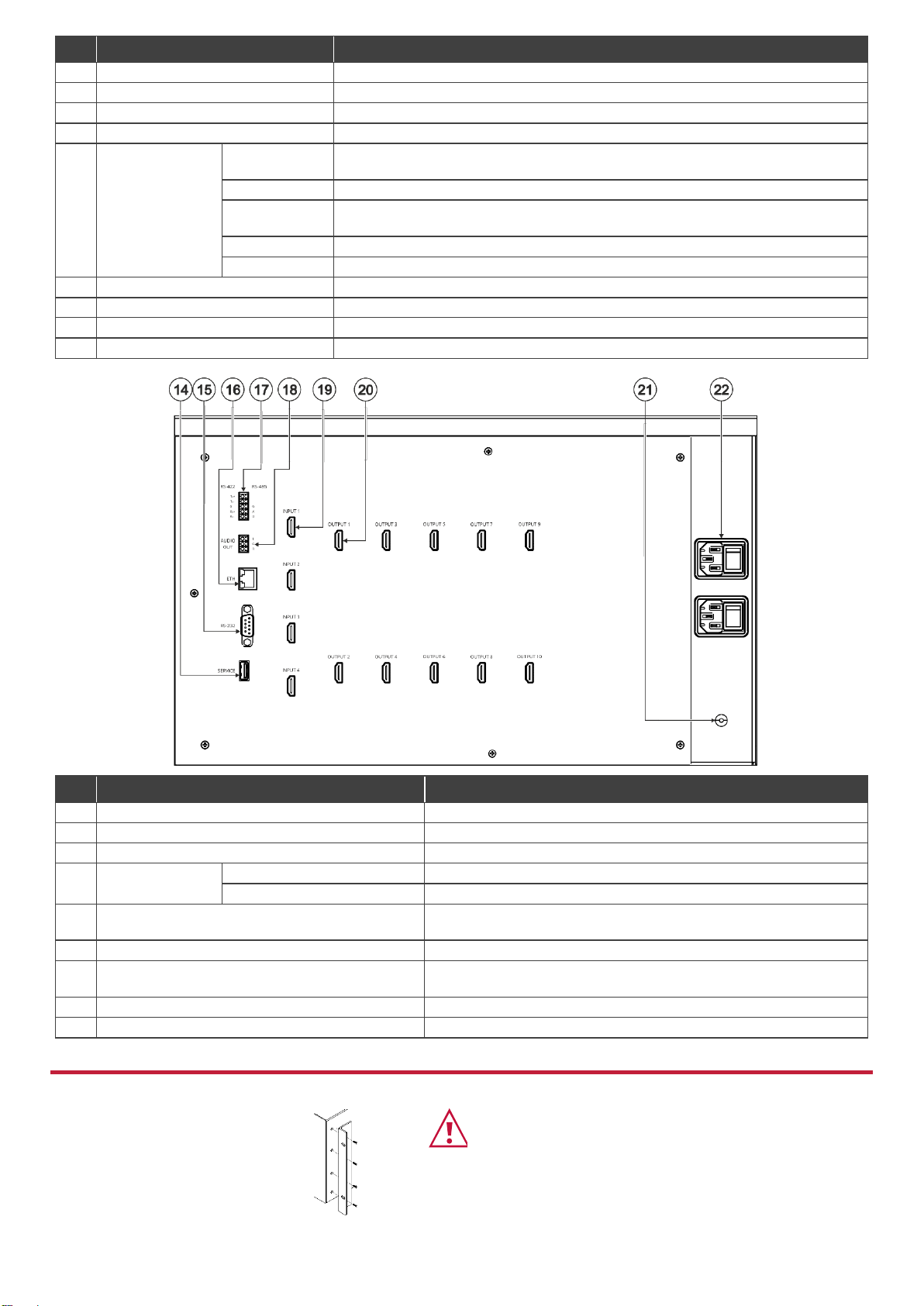
Connect to a PC to perform firmware upgrade.
15
RS-232 9-pin D-sub Serial Port Connector
Connect to a PC/serial controller
16
ETHERNET RJ-45 Connector
Connect to a PC or other serial controller via a LAN.
17
5-pin Terminal
Block Connector
RS-422 (Tx+, Tx-, G, Rx+, Rx-)
Connect to a PC/serial controller.
RS-485 (G, A, B)
Connect to a PC/serial controller.
18
AUDIO OUTPUT 3-pin Terminal Block Connector
(L, G, R)
Connect to an unbalanced stereo audio acceptor (for example,
powered speakers).
19
INPUT HDMI Connectors (1 to 4)
Connect to up to 4 HDMI sources.
20
OUTPUT HDMI Connectors (1 to 10)
Connect to 9 HDMI displays to create a 3x3 video wall. An additional
output can also be connected to an acceptor.
21
Grounding Opening
Use a M3 screw to lock the ground wire and connect to ground.
22
Mains Power Connector and Power Switch
Plug in the power cord and use the switch to power the unit on or off.
The terms HDMI, HDMI High-Definition Multimedia Interface, and the HDMI Logo are trademarks or registered trademarks of HDMI Licensing Administrator, Inc.
Step 3: Mount VW-9
To rack mount the machine, attach both
rack ears (by removing the screws from
each side of the machine and replacing
those screws through the rack ears) or
place the machine on a table.
•Ensure that the environment (e.g., maximum ambient
temperature & air flow) is compatible for the device.
•Avoid uneven mechanical loading.
•Appropriate consideration of equipment nameplate
ratings should be used for avoiding overloading of the
circuits.
•Reliable earthing of rack-mounted equipment should be
maintained.
Step 4: Connect inputs and outputs
Always switch OFF the power on each device before connecting it to your VW-9.
This diagram shows an example of configuring a 3x3 video wall in multi-viewer mode. Other configurations can be set via the
embedded webpages.
Step 5: Connect power
Connect the power cord to VW-9 and plug it into the mains electricity.
Safety Instructions (See www.kramerav.com for updated safety information)
Caution:
•For products with relay terminals and GPI\O ports, please refer to the permitted rating for an external connection, located next to the terminal or in the User Manual.
•There are no operator serviceable parts inside the unit.
Warning:
•Use only the power cord that is supplied with the unit.
•Disconnect the power and unplug the unit from the wall before installing.
•Do not open the unit. High voltages can cause electrical shock! Servicing by qualified personnel only.
•To ensure continuous risk protection, replace fuses only according to the rating specified on the product label which located on the bottom of the unit.
Step 6: Operate VW-9
Operate Product via:
•Front panel buttons.
•Remotely, by
RS-232/RS-422/RS-485 serial
commands transmitted by a
touch screen system, PC, or
other serial controller.
•Embedded web pages via the
Ethernet.
RS-232 Control / Protocol 3000
Baud Rate:
115,200
Parity:
None
Data Bits:
8
Command Format:
ASCII
Stop Bits:
1
Example: (mute video on output 1): #VMUTE 1,1
Default Ethernet Parameters
IP Address:
192.168.1.39
TCP Port #:
5000
Subnet Mask:
255.255.0.0
Gateway:
0.0.0.0.
Default Username:
Admin
Default Password:
Admin