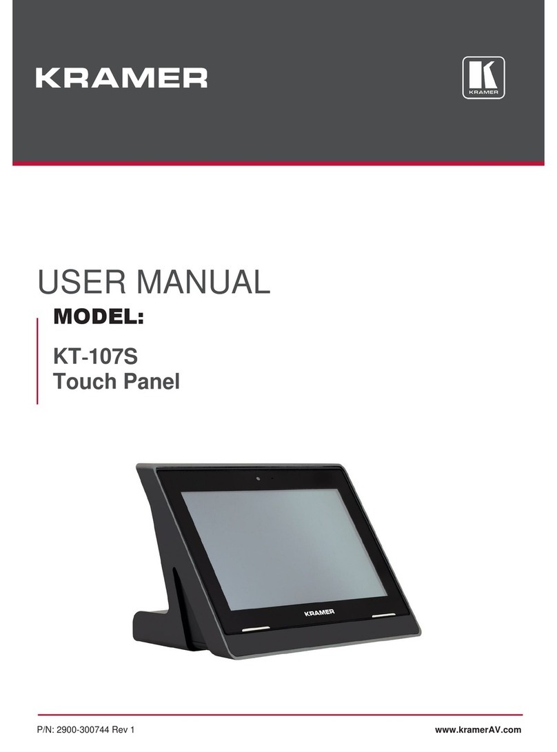
Kramer KT-107 User manual

KT-107, KT-107RB - Introduction
i
Contents
Introduction 1
Getting Started 1
Overview 2
Typical Applications 3
Defining the KT-107, KT-107RB 4
KT-107 Touch Panel 4
KT-107 Tabletop Mount 6
KT-107 On-Wall Mount 8
Mounting the KT-107, KT-107RB 9
Mounting the KT-107 on a Table 9
Mounting the KT-107 on a Wall 14
Connecting Options 21
Setting up the KT-107, KT-107RB 22
Initial Setup 22
Additional KT-107 Important Functions 28
Upgrading the Firmware 31
Setup your PC for Firmware Upgrade 31
Install the RockChip Driver Assistant 31
Prepare the KT-107 for Firmware Upgrade 33
Upgrade the Firmware via PC 33
Technical Specifications 37

Kramer Electronics Ltd.
KT-107, KT-107RB - Introduction
1
Introduction
Welcome to Kramer Electronics! Since 1981, Kramer Electronics has been providing a world of
unique, creative, and affordable solutions to the vast range of problems that confront the video,
audio, presentation, and broadcasting professional on a daily basis. In recent years, we have
redesigned and upgraded most of our line, making the best even better!
Our 1,000-plus different models now appear in 14 groups that are clearly defined by function:
GROUP 1: Distribution Amplifiers; GROUP 2: Switchers and Routers; GROUP 3: Control
Systems; GROUP 4: Format/Standards Converters; GROUP 5: Range Extenders and
Repeaters; GROUP 6: Specialty AV Products; GROUP 7: Scan Converters and Scalers;
GROUP 8: Cables and Connectors; GROUP 9: Room Connectivity; GROUP 10: Accessories
and Rack Adapters; GROUP 11: Sierra Video Products; GROUP 12: Digital Signage;
GROUP 13: Audio; and GROUP 14: Collaboration.
Getting Started
We recommend that you:
Unpack the equipment carefully and save the original box and packaging materials for
possible future shipment.
Review the contents of this user manual.
Go to www.kramerav.com/downloads/KT-107 to check for up-to-date user manuals,
application programs, and to check if firmware upgrades are available (where appropriate).
Achieving the Best Performance
Use only good quality connection cables (we recommend Kramer high-performance,
high-resolution cables) to avoid interference, deterioration in signal quality due to poor
matching, and elevated noise levels (often associated with low quality cables).
Do not secure the cables in tight bundles or roll the slack into tight coils.
Avoid interference from neighbouring electrical appliances that may adversely influence
signal quality.
Position your Kramer KT-107 away from moisture, excessive sunlight and dust.
This equipment is to be used only inside a building. It may only be connected to other
equipment that is installed inside a building.

Kramer Electronics Ltd.
KT-107, KT-107RB - Introduction
2
Safety Instructions (DC)
Caution:
There are no operator serviceable parts inside the unit
Warning:
Use only the Kramer Electronics power supply that is provided with the unit
Warning:
Disconnect the power and unplug the unit from the wall before installing
Recycling Kramer Products
The Waste Electrical and Electronic Equipment (WEEE) Directive 2002/96/EC aims to reduce
the amount of WEEE sent for disposal to landfill or incineration by requiring it to be collected
and recycled. To comply with the WEEE Directive, Kramer Electronics has made
arrangements with the European Advanced Recycling Network (EARN) and will cover any
costs of treatment, recycling and recovery of waste Kramer Electronics branded equipment on
arrival at the EARN facility. For details of Kramer’s recycling arrangements in your particular
country go to our recycling pages at www.kramerav.com/support/recycling/.
Overview
Congratulations on purchasing your Kramer KT-107/KT-107RB Touch Panel.
Throughout this manual KT-107 refers to both KT-107 and KT-107RB, unless specified
otherwise.
KT-107RB Wi-Fi 5GHz frequency band range is restricted to up to 5.35GHz.
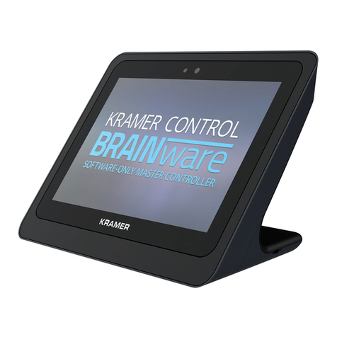
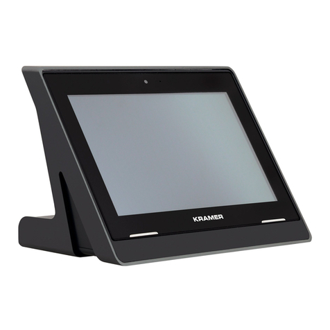
KT-107 is a 7-inch IPS multi-touch, powerful Touch Panel with 1280x800 resolution. The
elegantly designed portable Touch Panel can be deployed either on a table or on the wall.
KT-107 supports wired Power over Ethernet (PoE) and advanced Wi-Fi connectivity options.
To ensure easy installation with elegant wiring and secured mounting, the Touch Panel
comes with table and wall mounts, a USB cable and a power supply unit.
The KT-107 is an Android-based Touch Panel that is ideal for any 24/7 Kramer-supported
commercial AV or control application and features a user-friendly, fully customizable graphical
user interface configured by Kramer software.
The KT-107 provides exceptional quality, advanced and user-friendly operation, and high-level
security options.

Kramer Electronics Ltd.
KT-107, KT-107RB - Introduction
3
Exceptional Quality
Elegant Design –Smooth integration with room furniture, either on tables or walls, with
flexible panel cabling and locking design options.
Superior User Experience –IPS 1280x800 high-resolution screen with ±85° horizontal and
vertical wide viewing angles, built-in lighting sensor for auto-adaptable brightness,
advanced 10 multi-touch points, and 2-finger gesture capabilities.
Powerful Processing –Quad-core CPU, GPU, 2GB RAM, 16GB ROM processing
performance for smoothly running complicated media- and graphics-rich applications,
encoding and decoding H.265 video and audio streams, and seamlessly operating the
high-resolution 2Mp HD front camera.
Flexible Services –Advanced Android 6.0 Operating System with rich Kramer and
market-available software applications offered via cloud/store, such as K-Touch Control.
Advanced and User-friendly Operation
Easy Installation –Powering and connectivity via a single Ethernet cable.
Flexible Mounting –Including table and wall mounts that fit into standard market-available
2 Gang in-wall junction boxes.
Optional Connectivity –Simple wireless BTLE 4.0 Bluetooth as well as connection to USB
peripheral devices for either table or wall-mount installations, using the included USB
cable.
Reliable Networking –Seamless switching between wired and wireless 802.11ac
connectivity.
Versatile Powering Options –PoE, PSU and battery.
Auto Sensing –Optimized performance and operation according to automatically detected
LAN speed.
Firmware Upgrade –Via USB port.
Security
Secured Deployment –Flexible locking options to prevent unwanted panel-mount removal,
elegantly designed to remain out of site.
Secured Operation –Highly secured operation of applications such as password protected
exit, hidden control buttons and so on. Red LED alert when camera is active.
Typical Applications
The KT-107 is ideal for the following typical applications:
Control user interface in meeting and conference rooms, boardrooms, and auditoriums.
Presentation of room scheduling.

Kramer Electronics Ltd.
KT-107, KT-107RB - Defining the KT-107, KT-107RB
4
Defining the KT-107, KT-107RB
This section defines the KT-107 Touch Panel, the tabletop and the on-wall mounts.
KT-107 Touch Panel
This section defines the KT-107.
Figure 1: KT-107 Touch Panel Front and lower side Panel
#
Feature
Function
Hidden Reset Button
Located on top-side. Insert a pin and hold for a few seconds to reset
KT-107.
Light Sensor
Automatically adjusts the screen brightness according to the room
lighting conditions.
Activity RGB LED
Lights green when powered; flashes green when charging the
battery; lights red when camera is on.
Camera
For remote room viewing or video conferencing.
Microphone
For audio communication, recording or conferencing.
Speakers
To output the sound.
Control Button
Touch the Kramer logo area lightly to set the screen to sleep mode
or turn it back on.
Press and hold (for 1 to 2 seconds) to open the pop-up menu which
lets you power down the unit, reboot it or return to the Home-page.
Press twice to activate the camera.
Tabletop Mount Connector (on
the lower side)
For connecting to the tabletop mount (see Mounting the KT-107 on a
Table on page 9).

Kramer Electronics Ltd.
KT-107, KT-107RB - Defining the KT-107, KT-107RB
5
Figure 2: KT-107 Touch Panel Rear Panel
#
Feature
Function
Cover
Covers the wall mount connections and power button.
Power Button
Press to power on the KT-107.
When powered, press briefly to open the pop-up menu and power down
the device, reboot it or return to the Home-page.
Press and hold to power down the device immediately.
This button is also used for firmware upgrade (see Upgrade the
Firmware via PC on page 33).
U Button
Used for firmware upgrade.
Press to increase KT-107 speaker volume.
Micro USB Port
For connecting to an adjacent on-wall USB device and for firmware
upgrade.
Flat Cable Connector
For connecting to the on-wall mount unit (see Mounting the KT-107 on a
Wall on page 14).
Connecting Holes
For connecting to the tabletop mount or the panel mount plate
To prevent potential damage to the Touch Panel, use only
Kramer supplied screws and mounts (see Mounting the KT-107
on a Table on page 9).

Kramer Electronics Ltd.
KT-107, KT-107RB - Defining the KT-107, KT-107RB
6
KT-107 Tabletop Mount
This section defines the KT-107 tabletop mount.
Figure 3: Tabletop Mount Front View
#
Feature
Function
Screw Openings (x2)
For attaching the Touch Panel to the tabletop mount using the supplied
M2x4 screws (see Mounting the KT-107 on a Table on page 9).
M5x60 Secure Screw
Opening
For safely securing the tabletop mount to the table from underneath (see
Figure 8).

Kramer Electronics Ltd.
KT-107, KT-107RB - Defining the KT-107, KT-107RB
7
Figure 4: Tabletop Mount Rear View
#
Feature
Function
Micro USB Port
For connecting to an external USB device, such as a headset or a
memory disk.
Connect external devices only with the OTG type USB cable (supplied).
Regular USB cables (such as a smartphone data cable) can be used to
connect the device to a PC (for file transfer, and so on).
Power 2-pin Terminal Block
Connector
Connect to a power adapter and to the mains.
Cable Opening Knock-out
area
Cable pass-through area.
Screw Openings with Rubber
Covers (x2)
For covering the M2x4 screws that are used for attaching the KT-107 to
the tabletop mount (see Mounting the KT-107 on a Table on page 9).
Kensington Locker Port
For securely connecting the tabletop mount to a table with a
Kensington-compatible locker.
PoE Ethernet RJ-45 Port
Connect to the PoE-enabled Ethernet cable.
Cable Cover with Opening
Hides the ports and includes an opening for passing connected cables
over the table.
Solid Cable Cover
Hides the ports when passing connected cables under the table.

Kramer Electronics Ltd.
KT-107, KT-107RB - Defining the KT-107, KT-107RB
8
KT-107 On-Wall Mount
This section defines the KT-107 on-wall mount.
Figure 5: KT-107 Touch Panel Front Panel
#
Feature
Function
Groove (x4)
For hanging the panel mount plate (attached to KT-107) on a wall.
Flat Cable Connector
Connect to the rear side of the KT-107 using the supplied flat cable.
Passes the Ethernet signal and power to the KT-107.
Screw Opening (x8)
For attaching the on-wall mount unit to a standard in-wall junction box
(various holes fit different standard in-wall junction boxes), see Mounting the
KT-107 on a Wall on page 14.
Unit Cable Opening
Pass the supplied right-angle OTG USB cable through the opening to connect
to the rear side of the KT-107.
Indication Arrows
Top side up; shows the correct direction for mounting the on-wall mount unit
and for hanging the Touch Panel.
Screw Opening (x2)
For attaching the on-wall mount unit to a standard in-wall junction box
(various holes fit different standard in-wall junction boxes.
Indication Arrows
Top side up; shows the correct direction for hanging the panel mount plate.
Plate Cable Opening
Fits the opening on the on-wall mount unit. Pass the right-angle OTG USB
cable through the opening to connect to the rear side of the KT-107.
Screw opening (x4)
Attach the KT-107 to the panel mount plate using the supplied screws.
Cable opening
Pass the cables through the opening to connect to the rear side of the
KT-107.
Tab (x4)
For hanging the KT-107 with the attached panel mount plate on the on-wall
mount unit.

Kramer Electronics Ltd.
KT-107, KT-107RB - Mounting the KT-107, KT-107RB
9
Mounting the KT-107, KT-107RB
The KT-107 can be placed on a table or mounted on a wall.
Always be careful when attaching or removing the Touch Panel from either mounts.
Mounting the KT-107 on a Table
When mounting KT-107 on a table:
You can mount KT-107 either in secure mode or portable mode.
In secure mode, KT-107 is attached to the table (or other surface)
In portable mode, KT-107 is placed without damaging the table, is not secured and
can be moved.
The cables connected to KT-107 can be hidden by connecting them under the table via
the cable pass-through opening (in secure mode) or they can be connected over the table,
thus remaining visible (for both mounting modes).
Preparing the Table for a Secure Mount
To mount KT-107 in portable mode, go to Setting KT-107 on the Tabletop Mount on
page 12.
When mounting KT-107 on a table in secure mode, prepare the table as follows:
Drill a hole in the table to fit the M5x60 screw used for securing the tabletop mount to the
table.
Cut an opening in the table if you need to pass the cables from underneath.
The thickness of the table should be 76.2mm (3”) or less.

Kramer Electronics Ltd.
KT-107, KT-107RB - Mounting the KT-107, KT-107RB
10
Use the following cutout drawing to correctly measure the location of the M5x60 screw hole
and the cable pass-through opening:
Figure 6: Cut-Out Dimensions
The cut-out dimensions in Figure 6 are not to scale.
Refer to the cut-out template available on the Kramer website at
www.kramerav.com/downloads/KT-107.
Kramer Electronics is not responsible for any damage caused to the table.
To drill the M5x60 screw hole in a table:
1. Measure the exact location on the surface of the table where you want to install the
KT-107.
2. Drill a hole in the table and cut the cable pass-through opening with a saw according to
the dimensions shown in Figure 6 (not to scale).
Take care not to damage the table. Kramer Electronics is not responsible for any damage
caused to the table.
To cut the cable pass-through opening (if required):
1. Carefully measure the exact location of the cable pass-through opening.
Verify that the opening is correctly positioned in relation to the drilled M5x60 screw hole.
2. Cut out the cable pass-through opening.

Kramer Electronics Ltd.
KT-107, KT-107RB - Mounting the KT-107, KT-107RB
11
Secure the Tabletop Mount
To secure the KT-107 tabletop mount:
1. Remove the rubber covers from the rear tabletop mount.
2. Remove the cable cover .
Figure 7: Removing Cable Cover and Rubber Screw Cover
3. Place the tabletop mount on the table.

Kramer Electronics Ltd.
KT-107, KT-107RB - Mounting the KT-107, KT-107RB
12
4. Insert the M5x60 screw through the M5x60 screw opening to secure the tabletop
mount to the table at the desired location.
5. Tighten the screw from under the table using an M5 Wing nut or a regular M5 nut.
Figure 8: Securing Tabletop Mount
Setting KT-107 on the Tabletop Mount
Before you begin, verify that the cable cover is removed.
To connect the cables and set the KT-107 on the tabletop mount:
1. Connect the RJ-45 port on the tabletop mount to the PoE-enabled network.
2. Connect the power adapter to the Power 2-pin terminal block connector on the
tabletop mount and to the mains power.
3. Place the KT-107 over the tabletop mount (the Touch Panel is magnetically held in
place), by first inserting the lower part of the Touch Panel then carefully laying the
KT-107 in place.

Kramer Electronics Ltd.
KT-107, KT-107RB - Mounting the KT-107, KT-107RB
13
4. Wait for the Home-page to load.
We recommend that you complete KT-107 setup (see Setting up the KT-107, KT-107RB, on
page 22) before securing the KT-107 to the tabletop mount.
Once setup is complete, carry on with the installation process.
5. Secure the KT-107 to the tabletop mount using the two M2x4 screws (supplied) that are
inserted via the openings on the rear side of the tabletop mount.
6. Replace the rubber covers to hide the screws.
Figure 9: Connecting to the KT-107 Rear Panel
7. Connect the Ethernet and micro-USB cables by either passing the cables from
underneath the table via the cable opening (see Preparing the Table for a Secure Mount
on page 9), or by placing them over the table.

Kramer Electronics Ltd.
KT-107, KT-107RB - Mounting the KT-107, KT-107RB
14
8. Replace the appropriate cover (for under-the-table or over-the-table installation).
Figure 10: Replace the Cover
9. Optionally, lock the tabletop mount with a Kensington locker (not supplied).
Mounting the KT-107 on a Wall
KT-107 can be safely installed on a wall using standard 2 Gang in-wall junction boxes. The
cables are passed inside the wall and then connected to the rear side of the on-wall mount
unit.
Before mounting the KT-107 on a wall, you need to install a standard 2 Gang in-wall junction
box.
We recommend that you use any of the following standard 2 Gang in-wall junction boxes:
USA: 2 Gang electrical junction boxes.
Europe: 2 Gang in-wall junction box, 47mm minimum depth (DIN 49073).
UK: 2 Gang in-wall junction box, 137x75mm, 41mm minimum depth (BS 4662).
Other popular in-wall mounting boxes may also be available in the market (such as the
GEWISS 4 Gang 144x85x50mm box (GW 24 404)).

Kramer Electronics Ltd.
KT-107, KT-107RB - Mounting the KT-107, KT-107RB
15
Inserting the On-Wall Mount Unit
To mount the on-wall mount unit:
1. Attach the on-wall mount unit to the installed in-wall junction box, (top side up, see the
indication arrows on the mount ).
2. Screw the 4 wall-mounting screws (supplied) through the screw openings .
The on-wall mount screw openings are set in different locations to fit various types of
in-wall junction boxes.
Figure 11: Installing the On-Wall Mount Unit
3. Optionally, insert the supplied right-angle OTG USB port if you need to connect the
KT-107 to an external USB device.

Kramer Electronics Ltd.
KT-107, KT-107RB - Mounting the KT-107, KT-107RB
16
Connecting the flat Cable
The flat cable passes power and PoE-enabled Ethernet to the Touch Panel.
To connect the flat cable:
1. On the rear side of the KT-107, unscrew the cover and set the cover and screw aside.
Figure 12: Removing the Cover on the KT-107 Rear Side
2. Attach the panel mount plate, top side up (see arrows), to the rear of the KT-107.
3. Fit the connecting holes on the KT-107 to the screw holes on the panel mount .

Kramer Electronics Ltd.
KT-107, KT-107RB - Mounting the KT-107, KT-107RB
17
4. Insert the 4 M2x4 screws (supplied) and tighten.
Figure 13: Attaching the Panel Mount Plate to the Rear Side of the KT-107
5. Connect the flat cable between the on-wall mount and the KT-107.
Figure 14: Connecting the On-wall Mount Flat Cable
If you need to secure the KT-107 to the wall, use the Kramer KT-107-OWLK (purchased
separately).
For installation instructions, see Installing the On-Wall Secure Lock on page 19.

Kramer Electronics Ltd.
KT-107, KT-107RB - Mounting the KT-107, KT-107RB
18
6. Hang the KT-107 on the wall by sliding the tabs on the attached panel mount plate
over the grooves on the on-wall mount unit.
Figure 15: Hanging KT-107 on the Wall
Other manuals for KT-107
2
This manual suits for next models
1
Table of contents
Other Kramer Touch Panel manuals

Kramer
Kramer KT-10 User manual

Kramer
Kramer KT-208 User manual

Kramer
Kramer KT-7 User manual

Kramer
Kramer KT-1010 User manual

Kramer
Kramer KT-2010 User manual

Kramer
Kramer KT-2010 User manual

Kramer
Kramer KT-205WM User manual

Kramer
Kramer KT-1010 User manual

Kramer
Kramer KT-107 User manual

Kramer
Kramer KronoMeet KT-1010SC User manual