manuals.online logo
Brands
  1. Home
  2. •
  3. Brands
  4. •
  5. Kuryakyn
  6. •
  7. Motorcycle Accessories
  8. •
  9. Kuryakyn 7529 User manual

Kuryakyn 7529 User manual

INSTALLATION
CUSTOMER SERVICE
877.370.3604 (toll free)
INSTALLATION QUESTIONS
[email protected]
or call 715.247.2983
LIMITED WARRANTY
Küryakyn warrants that any Küryakyn products
sold hereunder, shall be free of defects in
materials and workmanship for a period of one
(1) year from the date of purchase by the
consumer excepting the following provisions:
●Küryakyn shall have no obligation in the event
the customer is unable to provide a receipt
showing the date the customer purchased the
product(s).
●The product must be properly installed,
maintained and operated under
normal conditions.
●Küryakyn makes no warranty, expressed or
implied, with respect to any gold plated
products.
●Küryakyn shall not be liable for any
consequential and incidental damages, including
labor and paint, resulting from failure of a
Küryakyn product, failure to deliver, delay in
delivery, delivery in nonconforming condition, or
for any breech of contract or duty between
Küryakyn and a customer.
●Küryakyn products are often intended for use in
specific applications. Küryakyn makes no
warranty if a Küryakyn product is used in
applications other than intended.
●Küryakyn electrical products are warranted for
one (1) year from the date of purchase by the
consumer. L.E.D.’S contained in components of
Küryakyn products will be warranted for defects
in materials and workmanship for 3 years from
the date of purchase where as all other
components shall be warranted for one(1) year.
This includes, but is not limited to; control
modules, wiring, chrome & other components.
●Küryakyn makes no warranty of any kind in
regard to other manufacturer¹s products
distributed by Küryakyn. Küryakyn will pass on
all warranties made by the manufacturer and
where possible, will expedite the claim on behalf
of the customer, but ultimately, responsibility for
disposition of the warranty claim lies
with the manufacturer.
ABOUT OUR CATALOG
For purchasing Küryakyn® products, you
can receive a complete catalog free of charge.
Send the Proof-of-Purchase below with
your address to: Küryakyn, P.O. Box 339,
Somerset, WI 54025.
Please indicate either Accessories Catalog for
Harley-Davidson® or GL & Metric Cruisers.
Be sure to ask your local dealer about other
Küryakyn® products, the motorcycle parts and
accessories designed for riders by riders.
©2005 Küryakyn USA® All Rights reserved.
PARTS INCLUDED
1 Ergo Plus Engine Guard for FLST
1 Hardware Kit for Ergo Guard Containing:
1 5/16” Flat Washer
1 5/16”-18 x 3/4” Socket Head Cap Screw (SHCS)
2 3/8”-16 x 1” Socket Head Cap Screws (SHCS) Full Thread
2 3/8”-16 Nylock Nut
2 3/8” Flat Washer
1 Anti-seize Packet
1 Brake Arm for Ergo Guard
1 Hardware Kit for Brake Arm Containing:
1CotterPin
1 Domed End Cap
1 5/16”-18 x 1-3/8” Flat Socket Cap Screw
1Spacer
1 Installation Instructions
Please read and understand entire instructions before starting installation.
THANK YOU FOR CHOOSING KϋRYAKYN!
IN ORDER TO PROTECT YOU AND OTHERS FROM POSSIBLE INJURY AND/OR
PROPERTY DAMAGE OR LOSS, PLEASE PAY CLOSE ATTENTION TO ALL
INSTRUCTIONS, WARNINGS, CAUTIONS AND ATTENTION NOTES REGARDING
THE USE AND CARE OF THIS PRODUCT.
WARNING! THIS INDICATION ALERTS YOU TO THE FACT THAT IGNORING
THE CONTENTS DESCRIBED HEREIN CAN RESULT IN
POTENTIAL DEATH OR SERIOUS INJURY.
ATTENTION! This indication alerts you to the fact that ignoring the contents
described herein may negatively affect product performance and
functionality.
CAUTION! This indication alerts you to the fact that ignoring the contents
described herein can result in potential injury or material
damage.
TOOLS SUGGESTED
Set of Hex Wrenches, Combination Wrenches, Socket Set and Ratchet
STRICTLY OBSERVE THE FOLLOWING GUIDELINES IN ORDER TO USE THE
PRODUCT PROPERLY AND AVOID POTENTIALLY DANGEROUS ACCIDENTS.
STEP 1 Read and understand all steps in the instructions before starting the
installation. Park the motorcycle on a hard, level surface and turn off the
ignition. Let cool.
WARNING! IF INSTALLING THIS PRODUCT FOR ANOTHER PARTY, PLEASE
MAKE SURE THEY RECEIVE THIS COPY OF THE INSTALLATION
INSTRUCTIONS SO THEY ARE AWARE OF THESE IMPORTANT
WARNINGS.
ERGO PLUS ENGINE GUARD 7529
7529-22HD-0112
-cont.-
PAGE
2
WARNING! THE ERGO GUARD MAY NOT BE COMPATIBLE WITH SOME EXTENDED SHIFT
LEVERS. IT IS THE RESPONSIBILITY OF THE INSTALLER AND END
USER TO ENSURE THERE IS ADEQUATE CLEARANCE BETWEEN
THE SHIFT LEVER AND THE ERGO GUARD.
WARNING! THE ERGO GUARD IS NOT DESIGNED OR INTENDED TO PROVIDE
PROTECTION TO THE RIDER OR VEHICLE IN A CRASH OR
COLLISION.
WARNING! IMPROPER INSTALLATION OR USE OF THIS PRODUCT COULD
RESULT IN SERIOUS INJURY OR DEATH.
WARNING! THE INSTALLATION OF ERGO ENGINE GUARDS MAY AFFECT
GROUND CLEARANCE WHEN CORNERING.
WARNING! YOU WILL BE WORKING AROUND THE ENGINE AND EXHAUST
SYSTEM DURING INSTALLATION. ENSURE THAT THE ENGINE AND
EXHAUST SYSTEM HAVE FULLY COOLED TO PREVENT INJURY.
WARNING! THE INCLUDED BRAKE ARM MUST BE INSTALLED BEFORE
OPERATING THE MOTORCYCLE WITH THE ERGO PLUS BAR
INSTALLED. FAILURE TO DO SO MAY RESULT IN INHIBITED REAR
BRAKING CONTROL WHICH COULD RESULT IN SERIOUS INJURY
ORDEATH.
ATTENTION!
A factory service manual may be helpful in performing this installation.
Do not attempt to perform this installation if you are not confident in
your ability to complete all steps in the procedure; consult a trained
technician.
STEP 2 Cover the front fender with a soft cloth to prevent scratches.
CAUTION! Avoid damage to the motorcycle. Protect painted surfaces with a
soft cloth or blanket.
ATTENTION!
Ensure that the supplied anti-seize is applied to all threaded fasteners
before installation; this will make future removal of the fasteners easier.
STEP 3 Place the Ergo Guard in to position and loosely secure the center mounting point
using the supplied 5/16” Cap Screw and Washer. Do not fully tighten. See PIC 1
STEP 4 Loosely secure both the left and right lower mounting points using the 3/8” Cap
Screws, Flat Washers and Nylock Nuts. See PIC 2 and 3.
STEP 5 Verify the Ergo Guard is positioned correctly with no interference to the bike’s
controls.
CAUTION! Ensure that the installation of this product does not interfere with
the proper operation of the motorcycle before riding.
STEP 6 Tighten the bottom fasteners to 33 ft/lbs and the top fastener to 19 ft/lbs.
STEP 7 The Ergo Guard has dual-position footpegs; rotate the footpegs out from the Ergo
Guard to use in the extended position (PIC 4). Fold the footpegs in to the cutouts
on the Ergo Guard to use in the retracted position (PIC 5).
ERGO PLUS ENGINE GUARD INSTALLATION
-cont.-
PIC 1
PIC 2
PIC 4
PIC 5
USE 5/16” CAP SCREW
AND WASHER HERE
PIC 3 USE 5/16” CAP SCREW
AND WASHER HERE
RIGHT SIDE
LEFT SIDE
FOOTPEG FLIPPED OUT
FOOTPEG FOLDED IN
PAGE
3
STEP 8 To adjust the angle of the footpeg when it is extended, adjust the set-screw on the
footpeg (PIC 6). Back the screw out for a steeper angle and in for a flatter angle.
Blue Locktite will help prevent the set screws from moving.
ATTENTION!
It is the installer’s responsibility to ensure that all of the fasteners
(including preassembled) are tightened before operation of the
motorcycle. Küryakyn will not issue a warranty on components lost due to
improper installation. Periodic maintenance may be required.
BRAKE PEDAL INSTALLATION
WARNING! THE INCLUDED BRAKE ARM MUST BE INSTALLED BEFORE
OPERATING THE MOTORCYCLE WITH THE ERGO PLUS BAR
INSTALLED. FAILURE TO DO SO MAY RESULT IN INHIBITED REAR
BRAKING CONTROL WHICH COULD RESULT IN
SERIOUS INJURY OR DEATH.
STEP 1 Remove the right floorboard, stock brake pedal and linkage
STEP 2 Slide the new brake pedal in to place on the pivot shaft. PIC 7
NOTE:
On 2000 and later models the spacer included must be
greased and placed at the end of the pivot shaft to lengthen
it or the brake pedal will bind. When the spacer is installed,
the end of the spacer will protrude slightly out of the end of
the brake pedal. Secure with the new End Cap and Socket
Cap Screw. PIC 7 Tighten to 12-16 ft/lbs.
STEP 3 Re-attach the stock brake linkage in reverse order it was removed
using the new cotter pin and OEM clevis pin and washer. PIC 8
Install the OEM fastener and washer to retain the brake pedal.
Tighten to 12-16 ft/lbs. Reattach the floorboard.
STEP 4 Test for proper brake function and inspect for any possible
interferences. Familiarize yourself with the new brake location
before operating the bike on public roadways.
CAUTION! Ensure that the installation of this product does not
interfere with the proper operation of the motorcycle
before riding.
ATTENTION!
It is the installer’s responsibility to ensure that all of the
fasteners (including preassembled) are tightened before
operation of the motorcycle. Küryakyn will not issue a
warranty on components lost due to improper installation.
Periodic maintenance may be required.
ATTENTION! Check clearance for proper operation of controls. Ergo guards provide additional
positions to place your feet/new-riding positions. Confirm clearance and relation of
the position of your feet to the shifter and the brake pedals.
Ride On!
ERGO PLUS ENGINE GUARD INSTALLATION
PIC 6
PIC 7
PIC 8
USE THIS
SETSCREW
TO ADJUST
PEG ANGLE
NEW PEDAL AND
HAREWARE INSTALLED
ON 2000 AND LATER
MODELS
NEW COTTER PIN
INSTALLED

Other Kuryakyn Motorcycle Accessories manuals

Kuryakyn 1796 User manual

Kuryakyn

Kuryakyn 1796 User manual

Kuryakyn 8637 User manual

Kuryakyn

Kuryakyn 8637 User manual

Kuryakyn 6212 User manual

Kuryakyn

Kuryakyn 6212 User manual

Kuryakyn 4141 User manual

Kuryakyn

Kuryakyn 4141 User manual

Kuryakyn 4162 User manual

Kuryakyn

Kuryakyn 4162 User manual

Kuryakyn 7925 User manual

Kuryakyn

Kuryakyn 7925 User manual

Kuryakyn 3765 User manual

Kuryakyn

Kuryakyn 3765 User manual

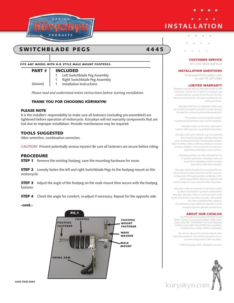
Kuryakyn 4445 User manual

Kuryakyn

Kuryakyn 4445 User manual

Kuryakyn ISO-SweptWing 4463 User manual

Kuryakyn

Kuryakyn ISO-SweptWing 4463 User manual

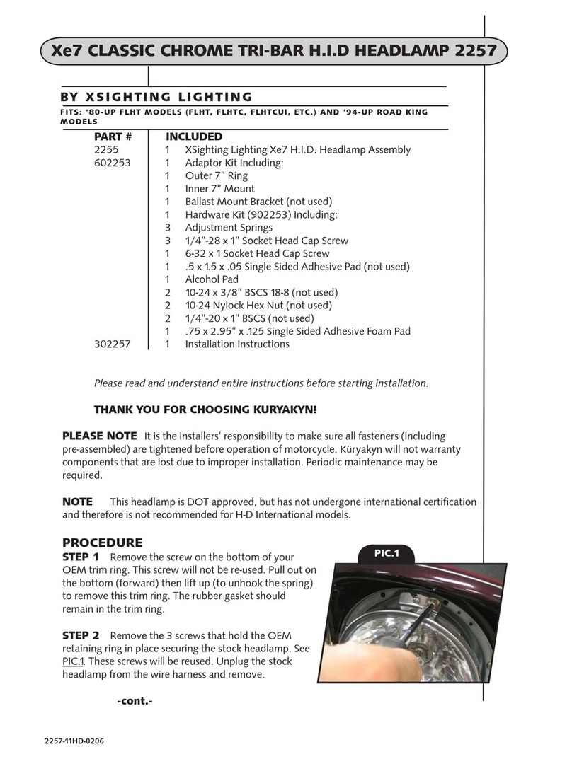
Kuryakyn 2257 User manual

Kuryakyn

Kuryakyn 2257 User manual

Kuryakyn 7704 User manual

Kuryakyn

Kuryakyn 7704 User manual

Kuryakyn 7151 User manual

Kuryakyn

Kuryakyn 7151 User manual

Kuryakyn 8617 User manual

Kuryakyn

Kuryakyn 8617 User manual

Kuryakyn 5455 User manual

Kuryakyn

Kuryakyn 5455 User manual

Kuryakyn MOMENTUM ROAMER TAIL BAG User manual

Kuryakyn

Kuryakyn MOMENTUM ROAMER TAIL BAG User manual

Kuryakyn MOMENTUM DEADBEAT DUFFLE BAG User manual

Kuryakyn

Kuryakyn MOMENTUM DEADBEAT DUFFLE BAG User manual

Kuryakyn 5062 User manual

Kuryakyn

Kuryakyn 5062 User manual

Kuryakyn 4261 User manual

Kuryakyn

Kuryakyn 4261 User manual

Kuryakyn 9252 User manual

Kuryakyn

Kuryakyn 9252 User manual

Kuryakyn 9559 User manual

Kuryakyn

Kuryakyn 9559 User manual

Kuryakyn 4139 User manual

Kuryakyn

Kuryakyn 4139 User manual

Kuryakyn 4247 User manual

Kuryakyn

Kuryakyn 4247 User manual

Kuryakyn 7158 User manual

Kuryakyn

Kuryakyn 7158 User manual

Kuryakyn 4143 User manual

Kuryakyn

Kuryakyn 4143 User manual

Popular Motorcycle Accessories manuals by other brands

Mastech KTM 790 Adventure Assembly instructions

Mastech

Mastech KTM 790 Adventure Assembly instructions

hepco & becker 501 668 00 01 manual

hepco & becker

hepco & becker 501 668 00 01 manual

Tool it Junon LCD 5/9-9/13 G manual

Tool it

Tool it Junon LCD 5/9-9/13 G manual

CyronMotor ABIG7-A6K URBAN user manual

CyronMotor

CyronMotor ABIG7-A6K URBAN user manual

KTM Power Parts 76012935044 Information

KTM Power Parts

KTM Power Parts 76012935044 Information

Ohlins YA 314 Mounting instructions

Ohlins

Ohlins YA 314 Mounting instructions

Scott SYMBOL 2 PLUS D user manual

Scott

Scott SYMBOL 2 PLUS D user manual

Maat APA-1200 Operation manual

Maat

Maat APA-1200 Operation manual

hepco & becker Sportrack manual

hepco & becker

hepco & becker Sportrack manual

hepco & becker 650.7505 00 01 Assembling instructions

hepco & becker

hepco & becker 650.7505 00 01 Assembling instructions

Twiins D3 instruction manual

Twiins

Twiins D3 instruction manual

FreedConn T-COMVB instruction manual

FreedConn

FreedConn T-COMVB instruction manual

AGV SportModular Booklet

AGV

AGV SportModular Booklet

MSA LH 050 Maintenance manual

MSA

MSA LH 050 Maintenance manual

CGM 209 instructions

CGM

CGM 209 instructions

Sealey MS062 quick start guide

Sealey

Sealey MS062 quick start guide

aXp RACING AX1706 Assembling instructions

aXp RACING

aXp RACING AX1706 Assembling instructions

ClearWater Lights Darla installation manual

ClearWater Lights

ClearWater Lights Darla installation manual

manuals.online logo
manuals.online logoBrands
  • About & Mission
  • Contact us
  • Privacy Policy
  • Terms and Conditions

Copyright 2025 Manuals.Online. All Rights Reserved.