Kuryakyn 4859 Operating and maintenance instructions

INSTALLATION
CUSTOMER SERVICE
877.370.3604 (toll free)
INSTALLATION QUESTIONS
or call 715.247.2983
LIMITED WARRANTY
Küryakyn warrants that any Küryakyn products
sold hereunder, shall be free of defects in
materials and workmanship for a period of one
(1) year from the date of purchase by the
consumer excepting the following provisions:
●Küryakyn shall have no obligation in the event
the customer is unable to provide a receipt
showing the date the customer purchased the
product(s).
●The product must be properly installed,
maintained and operated under
normal conditions.
●Küryakyn makes no warranty, expressed or
implied, with respect to any gold plated
products.
●Küryakyn shall not be liable for any
consequential and incidental damages, including
labor and paint, resulting from failure of a
Küryakyn product, failure to deliver, delay in
delivery, delivery in nonconforming condition, or
for any breech of contract or duty between
Küryakyn and a customer.
●Küryakyn products are often intended for use in
specific applications. Küryakyn makes no
warranty if a Küryakyn product is used in
applications other than intended.
●Küryakyn electrical products are warranted for
one (1) year from the date of purchase by the
consumer. L.E.D.’S contained in components of
Küryakyn products will be warranted for defects
in materials and workmanship for 3 years from
the date of purchase where as all other
components shall be warranted for one(1) year.
This includes, but is not limited to; control
modules, wiring, chrome & other components.
●Küryakyn makes no warranty of any kind in
regard to other manufacturer¹s products
distributed by Küryakyn. Küryakyn will pass on
all warranties made by the manufacturer and
where possible, will expedite the claim on behalf
of the customer, but ultimately, responsibility for
disposition of the warranty claim lies
with the manufacturer.
ABOUT OUR CATALOG
For purchasing Küryakyn® products, you
can receive a complete catalog free of charge.
Send the Proof-of-Purchase below with
your address to: Küryakyn, P.O. Box 339,
Somerset, WI 54025.
Please indicate either Accessories Catalog for
Harley-Davidson® or GL & Metric Cruisers.
Be sure to ask your local dealer about other
Küryakyn® products, the motorcycle parts and
accessories designed for riders by riders.
©2005 Küryakyn USA® All Rights reserved.
PARTS INCLUDED
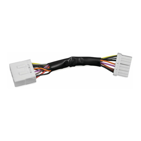
1 Run-Turn-Brake Controller Including:
1 “FLASH” Tab
1 Load Equalizer
1 Dielectric Grease Packet
1 Installation Instructions
Please read and understand entire instructions before starting installation.
THANK YOU FOR CHOOSING KϋRYAKYN!
IN ORDER TO PROTECT YOU AND OTHERS FROM POSSIBLE INJURY AND/OR
PROPERTY DAMAGE OR LOSS, PLEASE PAY CLOSE ATTENTION TO ALL
INSTRUCTIONS, WARNINGS, CAUTIONS AND ATTENTION NOTES REGARDING
THE USE AND CARE OF THIS PRODUCT.
ATTENTION! This indication alerts you to the fact that ignoring the contents
described herein may negatively affect product performance and
functionality.
CAUTION! This indication alerts you to the fact that ignoring the contents
described herein can result in potential injury or material
damage.
STRICTLY OBSERVE THE FOLLOWING GUIDELINES IN ORDER TO USE THE
PRODUCT PROPERLY AND AVOID POTENTIALLY DANGEROUS ACCIDENTS.
IMPORTANT INFORMATION: PLEASE READ BEFORE BEGINNING INSTALLATION
• This module is designed to work on motorcycles with rear wiring in stock-like
configuration. If the motorcycle is already equipped with an H-D accessory control
module or other aftermarket control module, it must be removed before installing the
Küryakyn Run-Turn- Brake Controller.
• The Küryakyn Run-Turn-Brake Controller is compatible with stock single circuit turn
signals as well as custom single circuit lights. If the stock turn signals have been
replaced with stock-style two-circuit lights or custom two-circuit lights, do not install
the Küryakyn Run-Turn-Brake Controller until the motorcycle is once again equipped
with single circuit lights and the motorcycle’s wiring has been return to its stock
configuration.
• Any existing load equalizers should be removed prior to installation of the Küryakyn
Run-Turn-Brake Controller. If for some reason they are still needed after installation
of the Run-Turn-Brake Controller, they can be reinstalled as directed in STEP 6c.
There should NEVER be a load equalizer installed between the Run-Turn-Brake
Control Module and the rear lights!
• This plug-in module adds a “Run”, “Turn”, and “Brake” function to existing single
circuit OEM, halogen or single circuit L.E.D. Silver Bullets, or single circuit LED rear
turn signals. To comply with State or Federal regulations, the turn signals must be
equipped with red lenses or red L.E.D.’s.
• It is possible that when installed on motorcycles equipped with H-D security systems,
the security system warning light may stay illuminated. This is a “false alarm” only –
alarm operation will be unaffected. If this warning light proves bothersome to you, it
may be eliminated with the addition of the Alarm Compatible Load Equalizer,
P/N 4857, sold separately.
REAR RUN-TURN-BRAKE CONTROLLER 4859
4859-24HD-1011 -cont.-
PAGE
2
CAUTION! Always install the load equalizer upstream of any existing aftermarket
multifunction control modules. Do not install a load equalizer between a
module and the turn signals as this will overload the module. Overloading will
damage the module and may create a fire hazard!
CAUTION! Load equalizers generate heat when in use. Avoid using the turn signals for an
extended period of time, otherwise the load equalizer will over heat. Never
operate the four-way flashers unless you first remove the load equalizer.
Overheating damages the load equalizer causing loss of turn signal operation
and could create a fire hazard!
CAUTION! Do not secure the load equalizer to the control module! Excess heat from
the load equalizer could damage the control module.
CAUTION! Avoid potential electrical shock! Disconnect the battery before starting this
procedure.
ATTENTION!
A factory service manual may be helpful in performing this installation. Do not attempt
to perform this installation if you are not confident in your ability to complete all of the
steps in the procedure; consult a trained technician.
NOTE:
Installation on ‘04-up Sportsters requires a 6 to 8 pin adapter, Kuryakyn P/N 4831, sold
separately.
NOTE:
Installation on ‘91-95 Softails, ‘91-96 Touring models, ‘94-’96 Road Kings,
‘91-’96 Dynas or ‘91-’98 Sportsters will require an 8 pin hardwire adapter, Kuryakyn
P/N 4832, sold separately.
STEP 1 Read and understand all steps in the instructions before starting the installation. Park the
motorcycle on a hard, level surface and turn off the ignition.
STEP 2 Remove the seat and disconnect the negative battery cable from the battery. Refer to the security
system section of your owner’s manual for special precautions and procedures relating to the
temporary disconnection of the battery. (If applicable)
STEP 3 Unplug the 8-pin rear fender lighting connector (black) found either under the seat or in the left
side electrical box. This connection will have plugs just like the Run-Turn-Brake Controller.
ATTENTION!
Küryakyn recommends the use of dielectric grease on electrical connections.
STEP 4 Apply dielectric grease to the 8-pin connectors on the Run-Turn-Brake Controller and plug it into
the motorcycles wiring harness.
STEP 5 Re-connect the negative battery cable.
REAR R-T-B CONTROLLER INSTALLATION
-cont.-
PAGE
3
STEP 6 Start the motorcycle and test the function of the Run-Turn-Brake Controller as follows:
a) Verify the tail lamp and turn signals are illuminated at “run” brightness.
b) Apply a brake; the tail lamp and turn signals will flash briefly then stay brightly lit as long as
you continue to apply the brakes. If you wish to disable the “flash brake” feature, turn off the
motorcycle and remove the flash tab from the controller with ignition in the “off” position. The
tab can be reinstalled to enable the “flash brake” feature, just make sure the ignition is in the
“off” position.
c)Test the operation of both turn signals with and without the brakes applied. If the turn signals
flash unusually fast or operate erratically, turn off the motorcycle and plug the provided load
equalizer into one of the empty 3-pin connectors on the Run-Turn-Brake Controller. Start the
bike and retest. If the turn signals still flash erratically, it will be necessary to add a second
load equalizer. Küryakyn LED conversions and LED Silver Bullets include a load equalizer, for
other types of custom lights, we recommend purchase of Küryakyn P/N 4810, sold separately.
The Run-Turn-Brake Controller is equipped with two 3-pin pigtails for connection of load
equalizers. Additionally, the 4810 load equalizer is also equipped a 3-pin connector. Simply
plug the second load equalizer into the second connector on the Run-Turn-Brake Controller.
ATTENTION! It is normal for the load equalizer to get warm when the turn signals are operating.
Never operate the 4-way ”Hazard Lights” without first unplugging the load equalizer.
Failure to remove the load equalizer will cause it to overheat and could possibly damage
themotorcycle.
STEP 7 Stow the Run-Turn-Brake Controller in the empty space under the seat or in the electrical box.
If possible, fasten the load equalizer to a frame tube as the frame will help to dissipate heat. If
that is not possible, tuck the load equalizer into an area where it will not contact any heat
sensitive components.
ATTENTION! Secure all wiring away from any moving parts, pinch points or extreme heat. Küryakyn
WILL NOT issue a warranty on any electrical component that fails due to pinched,
crimped, broken, abraded, melted or frayed wires.
STEP 8 Replace the seat and side cover if removed.
NOTE:
Illuminating the rear turn signals through the use of the Run-Turn-Brake Controller
adds additional load to the motorcycle’s “running light” circuit. It is uncommon, but
occasionally the installation of the Run-Turn-Brake Controller overloads the “running
light” circuit and causes a blown fuse. This situation can easily be rectified by
interchanging the positions of the orange and blue wires in the stock connector on the
input side of the Run-Turn-Brake Controller. Exchanging these two wires transfers the
electrical load required to light the taillights and turn signals from the “running light”
circuit to the “accessory” circuit of the motorcycle.
Ride On!
REAR R-T-B CONTROLLER INSTALLATION
Other Kuryakyn Motorcycle Accessories manuals

Kuryakyn
Kuryakyn 1558 User manual

Kuryakyn
Kuryakyn 4141 User manual

Kuryakyn
Kuryakyn 7158 User manual

Kuryakyn
Kuryakyn 7738 User manual

Kuryakyn
Kuryakyn 5496 User manual

Kuryakyn
Kuryakyn 4247 User manual

Kuryakyn
Kuryakyn 4261 User manual

Kuryakyn
Kuryakyn 3225 User manual

Kuryakyn
Kuryakyn 8446 User manual

Kuryakyn
Kuryakyn 4139 User manual

Kuryakyn
Kuryakyn 9559 User manual

Kuryakyn
Kuryakyn 9252 User manual

Kuryakyn
Kuryakyn 1186 User manual

Kuryakyn
Kuryakyn 4162 User manual

Kuryakyn
Kuryakyn 9931 Service manual

Kuryakyn
Kuryakyn 7704 User manual

Kuryakyn
Kuryakyn XKURSION XW PORTER BAG User manual

Kuryakyn
Kuryakyn 6745 User manual

Kuryakyn
Kuryakyn 7529 User manual

Kuryakyn
Kuryakyn 4445 User manual