Lumel P300 User manual

1
1
PULSE, FREQUENCY
AND RUNNING TIME
TRANSDUCER
P30O
USER’S MANUAL

2
2

3
3
Table of contents
1. APPLICATION........................................................................ 6
2. TRANSDUCER SET.................................................................. 8
3. BASIC REQUIREMENTS, OPERATIONAL SAFETY .............................. 8
4. INSTALLATION ...................................................................... 9
4.1. Mounting method ............................................................. 9
4.2. External connections diagrams............................................ 10
4.3. Connection examples ...................................................... 12
5. OPERATION......................................................................... 14
5.1. P30o transducer front panel description ................................ 14
5.2. Messages after switching on the power.................................. 15
5.3. Key functions ................................................................. 16
5.3.1. Individual key functions .................................................. 16
5.3.2. Functions of key combinations ......................................... 18
5.3.3. Programming matrix...................................................... 20
5.4. Programming transducer parameters .................................... 21
5.4.1. Changing the value of the selected parameter ....................... 28
5.4.2. Changing floating-point values ......................................... 28
5.4.3. Programmable transducer parameters ................................ 29
5.5. Transducer functions ........................................................ 48
5.5.1. Measurement inputs ...................................................... 48
5.5.1.1. Standard measurement input types.................................. 49
5.5.1.2. Special measurement input types.................................... 51
5.5.1.3. Averaging time of measured values ................................. 58
5.5.1.4. Filtering input signals.................................................. 58

4
4
5.5.1.5. Maximum measurement time ........................................ 59
5.5.1.6. Automatic reset of counter values ................................... 62
5.5.1.7. Maximum and minimum values of measured signals ............ 62
5.5.1.8. Mathematical operations on measured values .................... 63
5.5.1.9. Scaling with a constant value......................................... 66
5.5.1.10. Mathematical functions .............................................. 66
5.5.1.11. Input correlation....................................................... 66
5.5.1.12. Input individual characteristic ...................................... 67
5.5.1.13. Displayed value range limitation ................................... 69
5.5.1.14. Example of transducer configuration............................... 69
5.5.2. Analog output .............................................................. 73
5.5.2.1. Analog output individual characteristic ............................. 73
5.5.2.2. Analog output overflow management ............................... 75
5.5.3. Alarm and power outputs ................................................ 78
5.5.4. LCD display ................................................................ 80
5.5.4.1. Custom unit definition ................................................. 82
5.5.4.2. Displaying two values with their units............................... 82
5.5.5. Writing and reading transducer configuration from file............. 84
5.5.5.1. Storing the transducer configuration file............................ 85
5.5.5.2. Reading the transducer configuration file .......................... 85
5.6. Default settings .............................................................. 86
5.7. Firmware update............................................................. 91
5.8. Archiving measured values ................................................ 93
5.8.1. Transducer memory structure ........................................... 93
5.8.2. Internal memory........................................................... 94
5.8.2.1. Record structure ........................................................ 95
5.8.2.2. Downloading archived data from the internal memory ........... 96

5
5
5.8.3. Archiving configuration................................................... 97
5.8.4. Memory card or internal file system memory (option) ............ 100
5.8.5. Archive file structure.................................................... 102
5.9. RS-485 Interface ........................................................... 104
5.9.1. Serial interface connection ............................................ 104
5.9.2. MODBUS protocol description......................................... 105
5.9.3. Description of the implemented functions .......................... 106
5.9.4. Register map............................................................. 110
5.9.5. Read and Write registers .............................................. 112
5.9.6. Read-only registers ..................................................... 140
5.10. 10/100-BASE-T Ethernet interface.................................... 148
5.10.1. Connecting 10/100-BASE-T Ethernet interface .................... 148
5.10.2. WWW server ........................................................... 150
5.10.2.1. Website general view .............................................. 151
5.10.2.2. WWW user selection ............................................... 151
5.10.3. FTP Server ............................................................. 153
5.10.3.1. FTP user selection .................................................. 153
5.10.4. TCP/IP Modbus......................................................... 155
6. ACCESSORIES.................................................................... 156
7. ERROR CODES ................................................................... 156
8. TECHNICAL SPECIFICATIONS.................................................. 158
9. ORDERING CODE ................................................................ 162

6
6
1. APPLICATION
The programmable transducer P30o type has been desig-
ned to convert the number of pulses, frequency, period, running time
and encoder position into a standard direct current or direct voltage.
The transducer has also been fi tted with a signal setting function.
The output signal is galvanically isolated from the input signal and power
supply. The transducer is fi tted with a 2x8 LCD screen.
Features of the P30o transducer:
• 2 independent, universal measurement inputs separated galvanically,
• binary inputs controlling the operation of the main input separated
galvanically from inputs,
• controlling the main counter operation via transducer keypad,
• auto counter resetting at preset value,
• fi ltering input signal used in conjunction with mechanical setters,
• converting measured values into any output signal based on an in-
dividual linear characteristic,
• calculating measured values using one of fi ve implemented mathe-
matical functions,
• calculating measured values based on a 21-point individual charac-
teristics,
• one or two NO (normaly open) relay alarms operating in 6 modes,
• auxiliary power supply 24V DC 30mA switched on/off by software
(options),
• indication of exceeding the alarm values set,
• programming alarm and analog outputs with a reaction to selected
input value
• (main input, auxiliary input or RTC),
• real time clock (RTC) with independent battery supply,
• recording the input signals in programmed time periods in the inter-
nal memory and on an SD/SDHC card (option),
• internal archive memory with 534336 record capacity,
• automatic decimal point setting,

7
7
• preview of preset parameters,
• password protected parameter change,
• RS-485 interface support with the MODBUS protocol in RTU mode,
• programmable averaging time,
• SD/SDHC memory cards support – compatible with FAT and FAT32
fi le system (option),
• 10/100 BASE-T Ethernet interface (option)
- protocol: Modbus TCP/IP, HTTP, FTP,
- services: WWW server, FTP server, DHCP client.
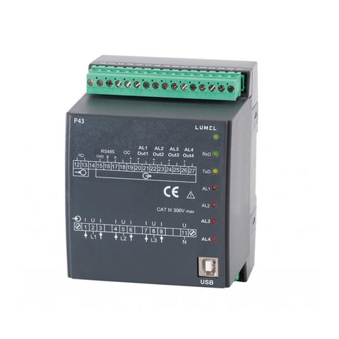
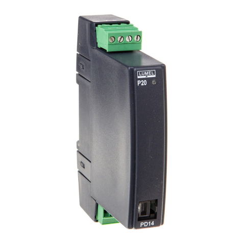
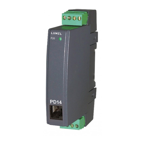
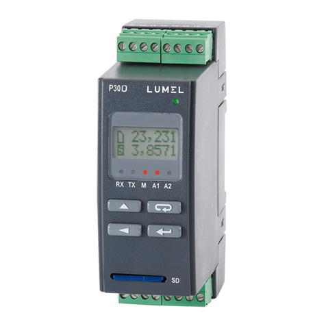
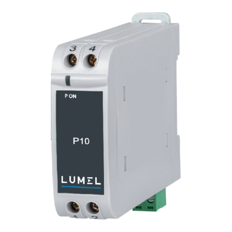
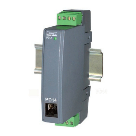
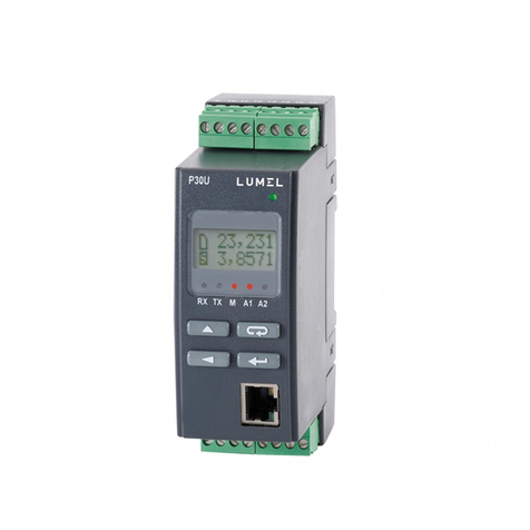
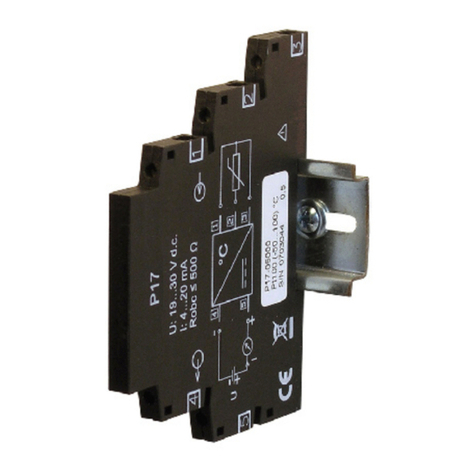
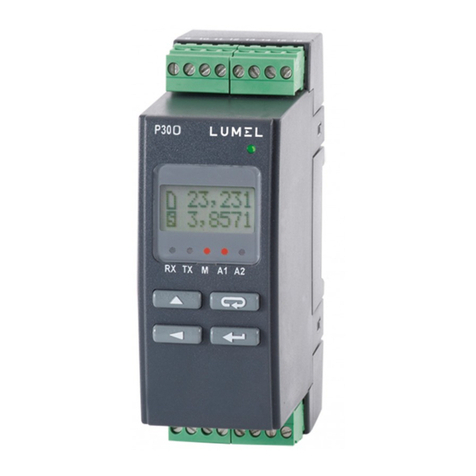
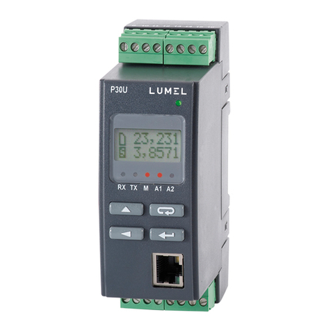
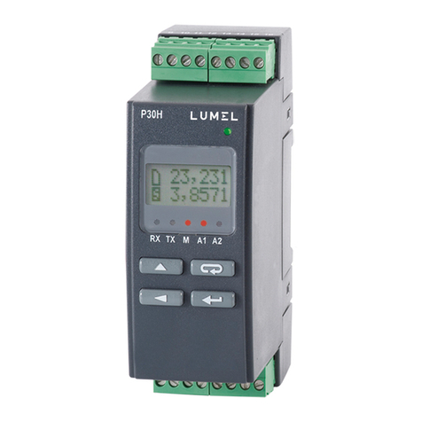
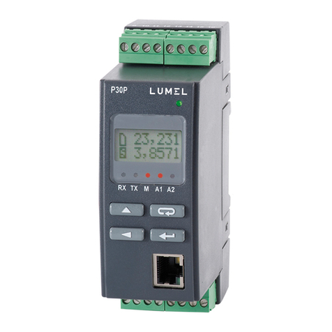
Fig. 1. Various variants of P30o transducer

8
8
2. TRANSDUCER SET
• transducer set 1 pcs.
• user’s manual 1 pcs.
• guarantee card 1 pcs.
• plug-able screw terminal blocks 4 pcs.
3. BASIC REQUIREMENTS, OPERATIONAL
SAFETY
The transducer meets the requirements of EN 61010-1 standard
in terms of operational safety.
Safety precautions:
• The assembly and installation of electrical connections must be car-
ried out by a person authorized to install electrical equipment.
• Before switching the transducer on, one must check the correctness
of connections.
• The device is destined to be installed and used in industrial electro-
magnetic environment conditions.
• The building installation should be equipped with a switch
or an automatic circuit breaker located near the device, which should
be easy accessible by the operator and properly marked
• Removal of the transducer housing during the warranty period may
cause its invalidation.

9
9
4. INSTALLATION
4.1. Mounting method
P30 transducers should be mounted on a 35 mm rail bracket
according to EN 60715. Dimensions and method of mounting hare
shown in fi gure 2.
Fig. 2. Overall dimensions and method of mounting
the transducer
Lock

10
10
4.2. External connections diagrams
Fig. 3. External connections diagram of the P30o transducer
Shielded cables should be used for connecting input signals
in environments with high level of perturbations. Physical measure-
ment inputs have been marked with INP1 and INP2 symbols, these are
the physical transducer inputs corresponding, respectively, to the main
input and the auxiliary input defi ned for the purposes of transducer
confi guration. The main input and the auxiliary input have been divided
into types depending on the measured physical value. An exception
to that are types of inputs from the main input group that physically use
two external input signals: Counter IN1-IN2 and Encoder.
The method of using physical measurement inputs depending
on the selected type of the main input or the auxiliary input has
been shown in table 1. Detailed information on types and functions
of measurement inputs have been discussed in section 5.5.1.

11
11
Used physical
inputs
No. of terminals
required
for connection
Input type Main input Auxiliary
input
Main
input
Auxiliary
input
Pulse Count.
INP1 WE2
1,2 3,4
Freq. f<10kHz
Rotary speed
Period T<20s
Period T<1,5h
Freq. f<1MHz
Running time
INP1
(high level on
INP1 required
for counting
running time)
WE2
(high level on
INP2 required
for counting
running time)
Current time none none none none
Setting Value - none -
Counter IN1-IN2 INP1, INP2 -1,2,3,4 -
Encoder -
Table 1
Inputs marked with symbols “START/STOP” and “RESET” are control
inputs (for main inputs counter type).

12
12
4.3. Connection examples
An example connection between P30o transducer and
inductive sensor with NPN or PNP output type is shown on fi g.
4. The method of connecting the transducer with contactron/re-
lay type outputs is shown on fi g. 5. Examples show the connection
of both main auxiliary inputs for measuring the same signal. Volt-
ages controlling the inputs should be within 5...24 V DC range.
Fig. 4. Connection diagram for the sensor with an OC output:
a) PNP type, b) NPN type

13
13
Fig. 5. Connection diagram for the sensor with a contactron/
relay type output

14
14
5. OPERATION
5.1 P30o transducer front panel description
Fig. 6. Front panel description
Note: The memory card (option) should be inserted to the transducer
slot with contacts facing down.
LED indicator description:
RX – green diode – Date reception on RS-485 indicator
TX – yellow diode – Date transmission on RS-485 indicator

15
15
M – red diode – full internal memory indicator or writing fi le
to SD/SDHC memory indicator, when the internal memory
usage exceeds 95%, the diode is constantly on, if the trans-
ducer operates with an installed memory card, then the LED
fl ashes when Date is being written on the card.
A1 – red diode – indicator of switching on the fi rst alarm
A2 – red diode – indicator of switching on the second alarm
or 24V d.c. power supply
Power indicator – green diode.
5.2. Messages after switching on the power
After connecting external signals and switch the power supply
on which is signalled with a green LED (power indicator), the transdu-
cer displays the type, current firmware version and the serial number.
If the transducer is equipped with Ethernet interface (P30o-X2XXXXXX)
IP address is displayed after serial number (stored in memory
or received from the DHCP server).
Fig. 7. Start-up messages of a transducer not equipped
with an Ethernet interface
Fig. 8. Start-up messages of a transducer equipped
with an Ethernet interface

16
16
5.3. Key functions
5.3.1. Individual key functions
- accept key
• enters programming mode (hold for about 3 seconds).
• navigates the menu – level select,
• enters parameter value change mode,
• accepts the changed parameter value,
• changes the content displayed in the lower line of the display
• switching the transducer power supply on while holding this key
enters the software update mode through the RS-485 interface,
connection parameters: rate 9600 kb/s, mode 8N2.
- increase value key
• displays the maximum value of the main input
• enters the parameters group level,
• navigates the selected level
• changes the value of a selected parameter – increase value,
After about fi ve seconds, the transducer automatically
switches to operating mode; it makes a measurement and converts
it into an analog output signal. It displays the measured value
in the top row of the display and auxiliary information in the bottom row
of the display (section 5.5.4). The LED indicator signals the transmis-
sion status on the RS-485 interface, status of the internal memory use
and alarm states. If transducer is equipped with an Ethernet interface,
Ethernet services start-up: WWW server, FTP server, TCP/IP Modbus.

17
17
• changes the preset value when the auxiliary input type Setting
Value is selected, increases the current setter value by the abso-
lute setter step, (see section 5.5.1.2),
- change digit key
• displays the minimum value of the main input,
• enters the parameters group level,
• navigates the selected level,
• changes the value of a selected parameter – switches to the sub-
sequent digit,
• changes the preset value when the auxiliary input type Setting
Value is selected, decreases the current setter value
by the absolute setter step, (see section 5.5.1.2),
• switching the transducer power supply on while holding this key
enters the software update mode through the RS-485 interface,
connection parameters: rate 15200 kb/s, mode 8N2.
- cancel key
• enters the transducer parameters preview menu (hold for about
3 seconds),
• exits the transducer parameters preview menu,
• changes the content displayed in the lower line of the display,
• cancel the parameter change,
• completely cancels the programming mode (hold for about 3 se-
conds).
• switching the transducer power supply on while holding the key
forces reading transducer confi guration from P30O_PAR.CON fi le
stored on an external SD/SDHC memory card or in the internal fi le
system memory (depending on the manufacturing variant).

18
18
5.3.2. Functions of key combinations
- hold for about 3 seconds
• clear alarm indication; this action works only when the alarm
indication memory function is switched on;
- hold for about 1 second
• the main input counter value reset - if the keypad counter control
function is switched on and the reset procedure is set,
the transducer will sequentially display at the upper line
of the display the message about reset and the permission
status for resuming pulse counting
a)
b)
Fig. 9. Messages after reset the main input counter using
the key combination, a) if the counter is stopped
after the clearing b)if the counter is not stopped
after the clearing
- hold for about 1 second
• stops counting on main input counter if the counting has been swit-
ched on before – works only if the keypad control counter function
is switched on; after the counter is stopped the message about
stopping the counter will be displayed on the upper display line

19
19
Fig. 10. Message that the main counter is being stopped
• start counting on main input counter if the counting has been swit-
ched off before - works only if the keypad control counter function
is switched on; after the counter is switched on the message about
starting the counter will be displayed on the upper display line
Fig. 11. Message that the main counter is switched on
- hold for about 1 second
• clears the maximum and minimum value for the main input
- hold for about 1 second
• unmounts the SD/SDHC memory card enabling safe removal –
for transducer equipped with an external SD/SDHC memory slot
- hold for about 1 second
• force start copying the archive from the internal memory into
the SD/SDHC memory card – for transducer equipped
with an external SD/SDHC memory slot
• force start copying the archive from the internal memory to the fi le
system memory – for transducer equipped with an Ethernet interfa-
ce; this action enables downloading current archive Date fi les from
the transducer via FTP protocol
Push and hold the programming key for about 3
seconds to enter the programming matrix. The programming matrix can
be protected with a safety code

20
20
5.3.3. Programming matrix
Fig. 12. P30o operation algorithm
Other manuals for P300
1
Table of contents
Other Lumel Transducer manuals