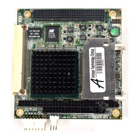
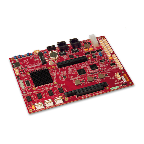
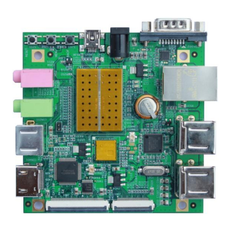
Lanner electronics PC/104 Single Board Computer with STPC Atlas CPU, and VGA, LCD, LAN, SSD, on-board RAM, 4xCOM,... User manual

PC-2400 Series
PC/104 Single Board Computer
with STPC Atlas CPU,
and VGA, LCD, LAN, SSD,
on-board RAM, 4xCOM, 2xUSB
USER'S MANUAL

COPYRIGHT©
This document is a copyright of the original manufacturer, 2004. The original manufacturer
reserves the rights to make improvement and/or modification to the product described in this
manual at any time without further notice. This manual may not, in whole or in part, be
photocopied, reproduced, transcribed, translated, or transmitted in whatever form without the
written consent of the manufacturer, except for copies retained by the purchaser for backup
purposes. All rights are reserved.
TRADEMARKS
The following are trademarks or registered trademarks of their respective companies: ST,
Phoenix-Award, Microsoft, Windows, Windows NT, Novell, SCO, PC/104, PICMG, UMC, Realtek, and
Winbond. Products mentioned in this manual are mentioned for identification purposes only. All
names of products or services appearing in this manual are the trademarks or registered
trademarks of their respective organizations and companies.
Copyright 2004
Version: 1.0
Date: 2004/05/20

TABLE OF CONTENTS
CHAPTER 1 INTRODUCTION .....................................................................................................................................1
1.1 INTRODUCTION ..........................................................................................................................................................1
1.2 FEATURES ..................................................................................................................................................................1
1.2 SPECIFICATION...........................................................................................................................................................2
1.3 UNPACK YOUR PC-2400 SERIES ................................................................................................................................3
1.4 BOARD LAYOUT .........................................................................................................................................................4
CHAPTER 2 INSTALLATION.......................................................................................................................................5
2.1 JUMPER SETTINGS AND CONNECTORS........................................................................................................................5
2.1.1 Board Outline.....................................................................................................................................................5
2.1.2 Jumper Settings Summary..................................................................................................................................6
2.1.3 I/O Connectors Summary...................................................................................................................................8
CHAPTER 3 BIOS SETUP............................................................................................................................................19
3.1 RUNNING AWARD BIOS ........................................................................................................................................19
3.2 CMOS SETUP UTILITY ............................................................................................................................................20
3.3 STANDARD CMOS SETUP........................................................................................................................................22
3.4 ADVANCED BIOS FEATURES....................................................................................................................................24
3.5 ADVANCED CHIPSET FEATURES ...............................................................................................................................26
3.6 INTEGRATED PERIPHERALS ......................................................................................................................................27
3.7 POWER MANAGEMENT SETUP..................................................................................................................................28
3.8 PNP/PCI CONFIGURATION .......................................................................................................................................30
3.9 LOAD OPTIMIZED DEFAULTS....................................................................................................................................32
3.10 SET SUPERVISOR / USER PASSWORD ......................................................................................................................33
3.11 SAVE & EXIT SETUP...............................................................................................................................................34
3.12 EXIT WITHOUT SAVING..........................................................................................................................................35
CHAPTER 4 DRIVERS SUPPORT..............................................................................................................................36
4.1 USE YOUR DRIVER CD-ROM..................................................................................................................................36
4.2 FILE DIRECTORY ......................................................................................................................................................36
APPENDIX A. WATCH-DOG TIMER.........................................................................................................................37
APPENDIX B. LCD BRIGHT CONTROL..................................................................................................................37
APPENDIX C. HOW TO USE DIGITAL I/O..............................................................................................................38
RMA SERVICE REQUEST FORM .............................................................................................................................40
Chapter1 Introduction
1
User’s Manual
Chapter 1 Introduction
1.1 Introduction
PC-2400 is a PC/104 CPU module powered by a STPC Atlas 133MHz processor. Responding to current market
trends and requirements, PC-2400 embeds stable features like TFT LCD, DiskOnChip, and WatchDog Timer, all
of which are designed based on most popular industrial applications.
Its 64MB onboard memory allows engineers to easily deploy PC-2400 for their specific application. The display
function of this CPU module likewise matches a wide variety of display applications. Thanks to its support for
both standard CRT interface and 18 bits TFT LCD panel.
Additional PC-2400 CPU module features include support for 4 COM ports, 2 USB ports, 8 digital inputs and 8
digital outputs, 1 LPT and 1 FDD. PC-2400 exhibits its I/O interface flexibility with an onboard support for both
standard IDE and DiskOnChip interfaces.
The PC-2400 incorporates an onboard LAN function, a very essential and convenient solution for users as the
Internet popularity and usage grow by the day. With the WatchDog function enabled, PC-2400 becomes a
perennial tool to any industrial control application.
If these onboard functions aren’t enough to satisfy your requisites, a PC/104 connector resides onboard for
your future "stackable" upgrade purposes.
1.2 Features
!" STPC Atlas 133MHz
!" Award BIOS
!" VGA and support 18-bit TTL LCD
!" LCD Brightness Control
!" Realtek RTL 8100C
!" DiskOnChip Socket
!" PC/104 expansion slot
!" 1 x LAN, 1 x FDD, 4 x COM, 1 x LPT, Keyboard & Mouse, 2 x USB, 1 x IrDA and 8 x DIO
!" Watchdog Timer

Chapter 1 Introduction
2 User’s Manual
1.2 Specification
PC-2400 Series
Processor : Embedded STPC Atlas 133 MHz processor
VGA Chipset : STPC Atlas
I/O Chipset : STPC Atlas, Winbond W83977F-A
System Memory / RAM : 64 MB SDRAM on board
Solid State Disk Support : DiskOnChip 32 pins DIP
Ethernet Controller : Realtek RTL 8100C, Support 10/100 Base T
IDE Interface : One enhanced IDE port
Floppy Interface : One Slim type floppy interface
Serial Port : Three RS-232 and one RS-232/422/485 ports
Parallel Port : One bi-directional parallel, support SPP/ECP/ EPP
Universal Serial Bus : Two USB V1.1 ports
Keyboard : Keyboard port on header
Mouse : Mouse port on header
RTC : Internal RTC with Li battery.
Battery : Lithium Battery
IrDA : Supports one IrDA Tx/Rx header
Digital I/O : 8 TTL digital input bits & 8 TTL digital output bits
BIOS : Award licensed BIOS 256KB
Watchdog Timer : 256 level software time-out intervals
LCD Support : 18-bits TFT LCD panel support
Operating Temperature : 0 degree Celsius ~60 degree Cesius
(Entended test for –20 degree Cesius~+70 degree Cesius)
Storage Temperature : -20 degree Celsius ~+85 degree Cesius
Humidity : 10%~95%RH, non-condensing
Power Requirements : +5 Voltages ±5%
Power Consumption : Typical : +5V @1.2A ( 64MB SDRAM )
Power Connector : AMP 4 pins 2.54 mm
Dimensions : 96 mm X 90 mm (3.775” ~ 3.55”)
Model Extension : PC-2400A Full function, fan-less

Chapter1 Introduction
3
User’s Manual
1.3 Unpack your PC-2400 Series
Before you begin to install your card, please make sure that you received the following materials as listed
below:
Standard Packing:
!" PC-2400 x 1 pc PC/104 module
!" Driver Utility CD-ROM x 1 pc Drivers & Utilities
!" User Manual x 1 pc User Manual
Note: All Option Kits are to be purchased separately
Option: PC-2400CB
!" IDE cable x 1 pc 0800001400001 44P-40P-40P,L:450mm
!" Floppy cable x 1 pc 0800100260002 26P Flat 200mm (up contact)
!" Floppy cable x 1 pc 0800100260007 26P Flat 200mm (down contact)
!" VGA cable x 1 pc 0800200150001 D-SUB 15P 2!6 2.0mm with key (P8), L:100mm
!" LAN cable x 1 pc 0800400120001 RJ45+2LED 2!6 2.0mm with key (P4), L:100mm
!" USB cable x 1 pc 0800100100013 4P x 2 Y cable, 2 x 5 2.0mm with key (P3,8), L:100mm
!" Print cable x 1 pc 0802100250001 D-SUB 25P 2 x 13, 2.0mm with key (P26), L:100mm
!" RS232 cable x 4 pc 0802700090001 D-SUB 9P, 2 x 5, 2.0mm with key (P10), L:100mm
!" KB/MS cable x 1 pc 0800100060001 6P x 2 Y cable, 2 x 4, 2.0mm with key (P3,5), L:100mm
!" IDE cable x 1 pc 080014445E001 44P-44P-44P, L:450mm
!" Spacer x 4 pcs 0703150151261 5.0 15mm hex-spacer with nut

Chapter 1 Introduction
4 User’s Manual
1.4 Board Layout

Chapter 2 Installation
5
User’s Manual
Chapter 2 Installation
2.1 Jumper Settings and Connectors
2.1.1 Board Outline
CPU
Battery
BIOS
CMOS1
SC2T2
SC2T1
COMB2
COMB1
COMB4
COMB3
LCD1
V
LCD1
V
GAB1
PS4S1
INVER1
CONB1
CONA1
PKMB1 PLRS1 IRDA1
SDOCB1
LANI1
USBH1
IDEA1
DIOB1 LPTA1
DOC1
1
1
1
1
1 1
1
1
1
1
1
1
1
1
1
1
1
1
1
1
1
B1
A1 C1
D1
FDCB1

Chapter 2 Installation
6 User’s Manual
2.1.2 Jumper Settings Summary
LOCATION FUNCTION
CMOS1 Clear CMOS Data
SC2T1/SC2T2 Select COM2 Type
VLCD1 Select Panel Voltage
SDOCB1 Select Flash Disk Address
!" CMOS1: Clear CMOS Data
Description CMOS1
Normal (Default) 1-2
Clear CMOS 2-3
!"SC2T1/SC2T2: Select COM2 Type
COM2 TYPE SC2T1 SC2T2
RS-232 (Factory) 1-2 1-5,2-6,3-7,4-8
RS-422 3-4 5-9,6-10,7-11,8-12
RS-485 5-6 5-9,6-10,7-11,8-12
Clear CMOS1
Normal (Default) CMOS1
3 2 1
CMOS1
3 2 1
3 2 1
RS-422
RS-485
RS-232
SC2T1 SC2T2
6
4
2
5
3
1
Default: 9 10 11 12
1 2 3 4
SC2T2
SC2T1
6
4
2
5
3
1
CMOS1
SC2T1 SC2T2
9 10 11 12
1 2 3 4

Chapter 2 Installation
7
User’s Manual
!"VLCD1:Select Panel Voltage
Panel Voltage VLCD1
+3.3V (Default) 1-2
+5V 2-3
"
""
"SDOCB1 : Select Flash Disk Address
Flash Disk Address SDOCB1
C800H~C9FFH 1-3,2-4
CC00H~CDFFH 1-3,4-6
D800H~D9FFH 3-5,2-4
DC00H~DDFFH 3-5,4-6
Default: VLCD1
3
2
1
VLCD1
3.3V (Default) 3
2
1
VLCD1
3
2
1
5V 3
2
1
SDOCB1
CC00H~CDFFH
SDOCB1
D800H~D9FFH
SDOCB1
SDOCB1
DC00H~DDFFH
6
4
2
5
3
1
SDOCB1
C800H~C9FFH
6
4
2
5
3
1
V
LCD1
SDOCB1

Chapter 2 Installation
8 User’s Manual
2.1.3 I/O Connectors Summary
!"PLRS1: Power LED, HD LED, Reset, Speaker Connector (11 Pin 2.54mm)
Pin No. Description
1 Power LED +
2 Power LED +
3 GND
4 HDD LED +
5 HDD LED -
6 RESET SW +
7 RESET SW – (GND)
8 External Speaker -
9 NC
10 NC
11 External Speaker +
LOCATION FUNCTION
PLRS1 Power LED, HD LED, Reset, Speaker Connector (11 Pin 2.54mm)
IRDA1 IRDA Connector
USBH1 USB Port #1 & #2 Connector
COMB1 Serial Port #1 Connector (Header)
COMB2 Serial Port #2 Connector (Header)
COMB3 Serial Port #3 Connector (Header)
COMB4 Serial Port #4 Connector (Header)
LPTA1 Parallel Connector (26 Pin 2.0mm Pitch Header)
DIOB1 8 bits digital Input/Output ports 2x10 2.00mm Header
IDEA1 IDE Interface Connector (44Pin 2.0mm Pitch Header)
LANI1 LAN Connector
VGAB1 External VGA Connector (12 Pin Header)
PKMB1 PS/2 Keyboard & Mouse Connector (2x4 Header 2.0mm )
LCD1 Panel LCD Connector (50Pin 1.0mm JST Header)
CONA1/CONB1 PC/104 Connector (8 bit/ 16bit)
DOC1 Disk-On-Chip Socket
PS4S1 4-Pin Power Connector (Small-4P)
INVER1 LCD INVERTER Connector
1 11
PLRS1 PLRS1

Chapter 2 Installation
9
User’s Manual
!"IRDA1: IRDA Connector
Pin No. Description
1 VCC
2 NC
3 IRRX
4 GND
5 IRTX
!"USBH1: USB Port #1 & #2 Connector
Pin No. Description Pin No. Description
1 USB_VCC 2 Ground
3 Key 4 USBD2+
5 USBD1- 6 USBD2-
7 USBD1+ 8 Key
9 Ground 10 USB_VCC
IRDA1
1 5 IRDA1
10
2
USBH1
9
1
USBH1

Chapter 2 Installation
10 User’s Manual
!"COMB1: Serial Port #1 Connector (Header)
Description
Pin No RS-232
1 Data Carrier Detect (DCD1 #)
2 Data Set Ready (DSR1 #)
3 Receive Data (RXD1)
4 Request To Send (RTS1 #)
5 Transmit Data (TXD1)
6 Clear To Send (CTS1 #)
7 Data Terminal Ready (DTR1 #)
8 Ring In (RI4)
9 Ground
10 KEY
!"COMB2 : Serial Port #2 Connector (Header)
Description
Pin No. RS-232 (Default) RS-422 RS-485
1 Data Carrier Detect(DCD2#)Transmit Data-(TXD-)Data-
2 Receive Data(RXD2)Transmit Data+(TXD+)Data+
3 Transmit Data(TXD2)Receive Data+(RXD+)NC
4 Data Terminal Ready(DTR2#)Receive Data-(RXD-)NC
5 Ground NC NC
6 Data set Ready(DSR2#)NC NC
7 Request To Send(RTS2#)NC NC
8 Clear To Send(CTS2#)NC NC
9 RI2# NC NC
10 KEY KEY KEY
10
2
9
1
COMB1
COMB1
COMB2
10
2
9
1
COMB2

Chapter 2 Installation
11
User’s Manual
!"COMB3: Serial Port #3 Connector(Header)
Description
Pin No RS-232
1 Data Carrier Detect (DCD3 #)
2 Data Set Ready (DSR3 #)
3 Receive Data (RXD3)
4 Request To Send (RTS3 #)
5 Transmit Data (TXD3)
6 Clear To Send (CTS3 #)
7 Data Terminal Ready (DTR3 #)
8 Ring In (R13)
9 Ground
10 KEY
!"COMB4: Serial Port #4 Connector(Header)
Description
Pin No RS-232
1 Data Carrier Detect (DCD4 #)
2 Data Set Ready (DSR4 #)
3 Receive Data (RXD4)
4 Request To Send (RTS4 #)
5 Transmit Data (TXD4)
6 Clear To Send (CTS4 #)
7 Data Terminal Ready (DTR4 #)
8 RI4#
9 Ground
10 KEY
COMB3
COMB4
10
2
9
1
COMB4
10
2
9
1
COMB3

Chapter 2 Installation
12 User’s Manual
!"LPTA1:
::
:Parallel Connector (26 Pin 2.0mm Pitch Header)
Pin No. Description Pin No. Description
1 Strobe # 2 Auto Form Feed
3 Data0 4 Error #
5 Data1 6 Initialize #
7 Data2 8 Printer Select IN #
9 Data3 10 Ground
11 Data4 12 Ground
13 Data5 14 Ground
15 Data6 16 Ground
17 Data7 18 Ground
19 Acknowledge # 20 Ground
21 Busy 22 Ground
23 Paper Empty 24 Ground
25 Printer Select 26 KEY
!"DIOB1:
::
:8 bits digital Input/Output ports 2x10 2.00mm Header
Pin No. Description Pin No. Description
1 DO0 2 DO1
3 DO2 4 DO3
5 DO4 6 DO5
7 DO6 8 GO7
9 GND 10 GND
11 DI0 12 DI1
13 DI2 14 DI3
15 DI4 16 DI5
17 DI6 18 DI7
19 GND 20 KEY
20
2
DIOB1
19
1
26
2
LPTA1
25
1
LPTA1
DIOB1

Chapter 2 Installation
13
User’s Manual
!"IDEA1 : IDE Interface Connector (44Pin 2.0mm Pitch Header)
Pin No. Description Pin No. Description
1 Reset # 2 Ground
3 Data 7 4 Data 8
5 Data 6 6 Data 9
7 Data 5 8 Data 10
9 Data 4 10 Data 11
11 Data 3 12 Data 12
13 Data 2 14 Data 13
15 Data 1 16 Data 14
17 Data 0 18 Data 15
19 Ground 20 NC
21 DMA REQ # 22 Ground
23 IOW # 24 Ground
25 IOR # 26 Ground
27 IOCHRDY 28 Ground
29 DMA ACK # 30 Ground
31 Interrupt 32 NC
33 SA 1 34 NC
35 SA 0 36 SA 2
37 HDC CS 0# 38 HDC CS 1#
39 HDD Active 40 Ground
41 VCC 42 VCC
43 Ground 44 NC
44
2
IDEA1
43
1
IDEA1

Chapter 2 Installation
14 User’s Manual
!"LANI1: LAN Connector
Pin No. Description Pin No. Description
1 TX+ 2 TX-
3 LGND 4 KEY
5 RX+ 6 RX-
7 T45 8 T78
9 LSPEED+ 10 LSPEED-
11 LNKACT+ 12 LNKACT-
!"VGAB1:External VGA Connector ( 12 Pin Header )
Pin No. Description Pin No. Description
1 R 2 Ground
3 G 4 Ground
5 B 6 Ground
7 H-SYNC 8 KEY
9 V-SYNC 10 Ground
11 Detect-display Data 12 Detect-display CLOCK
VGAB1
11
1
12
2
12
2
LANI1
11
1
LANI1
V
GAB1

Chapter 2 Installation
15
User’s Manual
!"PKMB1:PS/2 Keyboard & Mouse Connector (2x4 Header 2.0mm )
Pin No. Description Pin No. Description
1 KBCLK 2 GND
3 KEY 4 KBDATA
5 KEY 6 MSDATA
7 MSCLK 8 VCC
!"LCD1:Panel LCD Connector ( 50Pin 1.0mm JST Header )
Pin No. Signal Pin No. Signal
1 FVCC 2 FVCC
3 FHSYN 4 FVSYN
5 ENAB 6 NC
7 ENVEE 8 ENVDD
9 SFCLK 10 NC
11 GND 12 GND
13 TFT-R0 14 NC
15 TFT-R1 16 NC
17 TFT-R2 18 NC
19 TFT-R3 20 NC
21 TFT-R4 22 NC
23 TFT-R5 24 NC
25 TFT-G0 26 NC
27 TFT-G1 28 NC
29 GND 30 TFT-G2
31 NC 32 TFT-G3
33 NC 34 TFT-G4
35 NC 36 TFT-G5
37 NC 38 GND
39 TFT-B0 40 NC
41 TFT-B1 42 NC
43 TFT-B2 44 NC
45 TFT-B3 46 NC
47 TFT-B4 48 NC
49 TFT-B5 50 NC
7
5
3
1
8
6
4
2
PKMB1
PKMB1
LCD1
50 49
2 1
LCD1

Chapter 2 Installation
16 User’s Manual
!"CONA1:PC/104 Connector(
((
(8 bit)
))
)
!"CONB1:PC/104 Connector(
((
(16 bit)
))
)Description
CONA1 CONB1
Pin No. Row A Row B Row C Row D
1 IOCHCK# Ground Ground Ground
2 SD7 RSTDRV SBHE# MEMCS16#
3 SD6 +5V LA23 IOCS16#
4 SD5 IRQ9 LA22 IRQ10
5 SD4 -5V LA21 IRQ11
6 SD3 DRQ2 LA20 IRQ12
7 SD2 -12V LA19 IRQ15
8 SD1 0 WS# LA18 IRQ14
9 SD0 +12V LA17 DACK0#
10 IOCHRDY NC MEMR# DRQ0
11 AEN SMEMW# MEMW# DACK5#
12 SA19 SMEMR# SD8 DRQ5
13 SA18 IOW# SD9 DACK6#
14 SA17 IOR# SD10 DRQ6
15 SA16 DACK3# SD11 DACK7#
16 SA15 DRQ3 SD12 DRQ7
17 SA14 DACK1# SD13 +5V
18 SA13 DRQ1 SD14 MASTER#
19 SA12 REFRESH# SD15 Ground
20 SA11 SYSCLK NC Ground
21 SA10 IRQ7 --- ---
22 SA9 IRQ6 --- ---
23 SA8 IRQ5 --- ---
24 SA7 IRQ4 --- ---
25 SA6 IRQ3 --- ---
26 SA5 DACK2# --- ---
27 SA4 TC --- ---
28 SA3 BALE --- ---
29 SA2 +5V --- ---
30 SA1 OSC --- ---
31 SA0 Ground --- ---
32 Ground Ground --- ---
32
32
CONA1
CONB1
20
20
C 1
D 1
B 1
A 1
CONA1
CONB1
Table of contents
Other Lanner electronics Single Board Computer manuals

Lanner electronics
Lanner electronics MB-X66 Series User manual

Lanner electronics
Lanner electronics EM-551Series User manual

Lanner electronics
Lanner electronics IAC-F845 Series User manual

Lanner electronics
Lanner electronics IAC-F694 Series User manual

Lanner electronics
Lanner electronics IAC-F847 Series User manual

Lanner electronics
Lanner electronics EM-660 Series User manual

Lanner electronics
Lanner electronics EM-9560 Series User manual

Lanner electronics
Lanner electronics EM-561 Series User manual

Lanner electronics
Lanner electronics IAC-H668 Series User manual

Lanner electronics
Lanner electronics AP-545L User manual