manuals.online logo
Brands
  1. Home
  2. •
  3. Brands
  4. •
  5. Lantronix
  6. •
  7. Gateway
  8. •
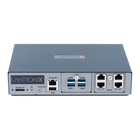
  9. Lantronix EMG 8500 User manual

Lantronix EMG 8500 User manual

Other manuals for EMG 8500

2

Other Lantronix Gateway manuals

Lantronix EDS-MD Series Installation manual

Lantronix

Lantronix EDS-MD Series Installation manual

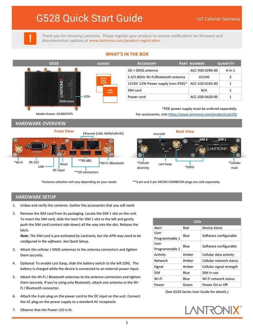
Lantronix G520 Series User manual

Lantronix

Lantronix G520 Series User manual

Lantronix EMG 7500 User manual

Lantronix

Lantronix EMG 7500 User manual

Lantronix PremierWave XN User manual

Lantronix

Lantronix PremierWave XN User manual

Lantronix SGX 5150 Operating and maintenance instructions

Lantronix

Lantronix SGX 5150 Operating and maintenance instructions

Lantronix FOX3-2G Series User manual

Lantronix

Lantronix FOX3-2G Series User manual

Lantronix X303 User manual

Lantronix

Lantronix X303 User manual

Lantronix EMG Series User manual

Lantronix

Lantronix EMG Series User manual

Lantronix PremierWave 2050 User manual

Lantronix

Lantronix PremierWave 2050 User manual

Lantronix X304 User manual

Lantronix

Lantronix X304 User manual

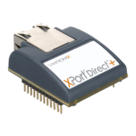
Lantronix DeviceLinx XPort Direct User manual

Lantronix

Lantronix DeviceLinx XPort Direct User manual

Lantronix PremierWave 2050 Quick setup guide

Lantronix

Lantronix PremierWave 2050 Quick setup guide

Lantronix G526 User manual

Lantronix

Lantronix G526 User manual

Lantronix PremierWave XC Installation manual

Lantronix

Lantronix PremierWave XC Installation manual

Lantronix PREMIERWAVE XC HSPA+ User manual

Lantronix

Lantronix PREMIERWAVE XC HSPA+ User manual

Lantronix SGX 5150 Installation manual

Lantronix

Lantronix SGX 5150 Installation manual

Lantronix PREMIERWAVE XC HSPA+ User manual

Lantronix

Lantronix PREMIERWAVE XC HSPA+ User manual

Lantronix EMG 8500 User manual

Lantronix

Lantronix EMG 8500 User manual

Lantronix X300 User manual

Lantronix

Lantronix X300 User manual

Lantronix PREMIERWAVE XC HSPA+ User manual

Lantronix

Lantronix PREMIERWAVE XC HSPA+ User manual

Lantronix xPico 900-619 Quick setup guide

Lantronix

Lantronix xPico 900-619 Quick setup guide

Lantronix EMG 8500 User manual

Lantronix

Lantronix EMG 8500 User manual

Lantronix G528 User manual

Lantronix

Lantronix G528 User manual

Lantronix X303 User manual

Lantronix

Lantronix X303 User manual

Popular Gateway manuals by other brands

Telecom FM onestream gfx Programming guide

Telecom FM

Telecom FM onestream gfx Programming guide

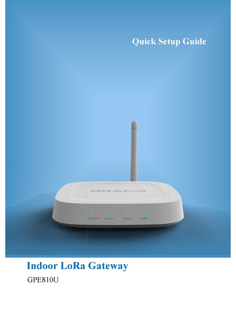
UfiSpace LoRa GPE810U Quick setup guide

UfiSpace

UfiSpace LoRa GPE810U Quick setup guide

Merak MMk-736F Quick setup guide

Merak

Merak MMk-736F Quick setup guide

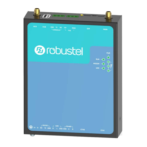
Robustel R3010 user guide

Robustel

Robustel R3010 user guide

turck BL20-PG-EN-V3 user manual

turck

turck BL20-PG-EN-V3 user manual

IBM Security Web Gateway Appliance quick start guide

IBM

IBM Security Web Gateway Appliance quick start guide

SSS Siedle Smart Gateway Commissioning instructions

SSS Siedle

SSS Siedle Smart Gateway Commissioning instructions

ADTRAN 424RG Installation

ADTRAN

ADTRAN 424RG Installation

Chorus Hyperfibre XGS-250WX-A user guide

Chorus

Chorus Hyperfibre XGS-250WX-A user guide

Dragino G308 user manual

Dragino

Dragino G308 user manual

Data Domain DD690g Installation and setup guide

Data Domain

Data Domain DD690g Installation and setup guide

Raritan Laptop Release notes

Raritan

Raritan Laptop Release notes

Haivision Torpedo quick start guide

Haivision

Haivision Torpedo quick start guide

ATCOM AG-268 user manual

ATCOM

ATCOM AG-268 user manual

LST M500RFE-AS Specification sheet

LST

LST M500RFE-AS Specification sheet

Vega VEGA BS-3 user manual

Vega

Vega VEGA BS-3 user manual

Kinnex Media Gateway quick start guide

Kinnex

Kinnex Media Gateway quick start guide

2N Telekomunikace 2N StarGate user manual

2N Telekomunikace

2N Telekomunikace 2N StarGate user manual

manuals.online logo
manuals.online logoBrands
  • About & Mission
  • Contact us
  • Privacy Policy
  • Terms and Conditions

Copyright 2025 Manuals.Online. All Rights Reserved.

1
Device Ports (Modular)
1. CTS (In)
2. DSR (In)
3. RX (In)
4. GND
5. GND
6. TX (Out)
7. DTR (Out)
8. RTS (Out)
Reversed by Default
Device Ports (RS-232)
Soware Reversible
1. HARDWARE OVERVIEW
3. HARDWARE INSTALLATION
The front console port allows a dumb terminal or PC with terminal emulaon soware
to locally access management funcons and connected devices.
The device ports allow simple and exible connecons to serial devices using adapters
and a standard CAT5 cable. Connect one end of the CAT5 cable to the device port and
the other end to an adapter that aaches to the serial console of the target system.
The default communicaon parameters for the device ports and console ports are:
• 9600 baud • 1 stop bit • 8 data bits • No ow control • No parity
Note: EMG 8500 device ports are reversed by default, and are soware congurable.
2. CONNECTING THE EMG 8500
Back View
EMG™ 8500 Quick Start Guide Edge Management
Gateway
1. RTS (Out)
2. DTR (Out)
3. TX (Out)
4. GND
5. GND
6. RX (In)
7. DSR (In)
8. CTS (In)
Console Port (RS-232)
!Thank you for choosing Lantronix. Please register the EMG 8500 in order to receive nocaons for
rmware and documentaon updates at www.lantronix.com/product-registraon.
Default Pin Assignments
EMG 8500Quick Start Guide Accessories Part Number Quanty
External Universal AC (100W, 12V) Power Supply ACC-520-0164-00 1
North American Power Cord - 110V AC power cord, 8 
(2.43m), RoHS ACC-500-041-R1
RJ45 to DB9F Adapter ACC-200.2070A 1
RJ45 to RJ45, CAT5 Cable, 6.6  (2 m) ACC-200.0062 1
RJ45 Loopback Cable ACC-500-153 1
Rubber feet with adhesive 120-008-R4 pieces
Addional I/O and Connecvity FRUs are available and
sold separately. varies varies
START
WHAT’S IN THE BOX
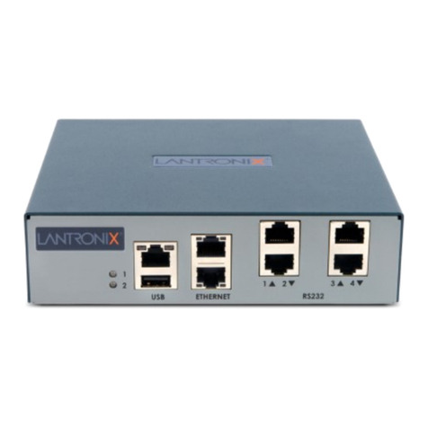
The EMG 8500 unit oers up to 8 RJ45 (RS-232) or USB
serial device port connecons in 2 user-swappable, front I/O
module device bays.
*Front DIO adapter is available and sold separately.
1. Install the unit on a desktop or other at, horizontal surface.
Rack mount and wall mount kits are available as oponal
accessories.
2. Install the I/O modules on the front of the unit and the
connecvity modules on the back.
Warning: Always remove the power cord prior to installing or
removing a connecvity or I/O module. Failure to do so could
damage the unit.
3. Connect the equipment to the device ports on the front of the
unit using the appropriate cables and adapters.
4. Connect the unit to the network using the upper network port
(Ethernet 1 or SFP 1).
Connecvity Ports
(Modular)
Bay 1 Bay 2 Ethernet SFP
Power
input
Front View
*DIO LEDs Console
Port
Micro SD USB
EMG851210SP with USB and RJ45 FRUs shown.
Addional FRU combinaons are available.
Not Reversible
Warning: If rack mounng the EMG,
do not block the air vents on the
sides of the unit. If mounted in an
enclosed rack, it is recommended
that the rack have a venlaon fan.
The back of the EMG 8500 unit oers up to 2 connecvity ports
for out-of-band management in 2 user-swappable module
bays.
5. Connect the power cord to apply power.
6. The top front LED turns green to indicate that power is ON and at least one
of the Ethernet ports has a link or both Ethernet ports are disabled. The LED
blinks red if none of the enabled Ethernet ports has a link.
7. Wait about a minute and a half for the boot process to complete. The rst
me you power up the EMG unit, Eth1 tries to obtain its IP Address via DHCP.
Bay 2Bay 1
2
5. RUN QUICK SETUP TO CONFIGURE NETWORK (IP) SETTINGS
© 2020 Lantronix, Inc. Lantronix is a registered trademark, and EMG is a trademark of Lantronix, Inc. All other trademarks are the
property of respecve owners. Specicaons subject to change without noce. 895-0004-00 Rev. B
Contact Technical Support
For technical support queries, visit hps://www.lantronix.com/support or call (800) 422-7044 Monday – Friday from 6:00 a.m. – 5:00 p.m.,
Pacic Time, excluding holidays.
Latest Firmware For the latest rmware downloads, visit hps://www.lantronix.com/support/downloads
6. LOGGING IN
To set up the network connecons, you may do one of the following:
 Complete the Quick Setup on the Web Manager.
 SSH to the command line interface and follow the Quick Setup
script
 Connect a terminal to the console (RS-232) port and follow the
Quick Setup script on the command line interface
SAFETY AND HAZARDS
To log in to the EMG 8500 web page:
1. Open a web browser.
2. In the URL eld, type hps:// followed by the IP address of the EMG.
3. Enter the default user credenals. Username: sysadmin and
Password: last 8 characters of the Device ID (for newly manufac-
tured devices that come installed with 8.2.0.1 or later) or PASS.
Note: If the Device ID is not set, the password is the last 8 characters
of the serial number.
The rst me you log in, the EMG 8500 Quick Setup page is displayed.
Subsequent logins will display the EMG 8500 Home Page.
4. Do one of the following:
• In Quick Setup, update the basic network parameters. Click Apply.
• Bypass the Quick Setup page to begin conguring the EMG. Click the
Accept default Quick Setup sengs checkbox and click Apply.
Aer you save the values for the EMG unit, the changes take eect
immediately.
Do not operate your EMG 8500 device:
• In areas where blasng is in progress
• Where explosive atmospheres may be present including refueling
points, fuel depots, and chemical plants
• Near medical equipment, life support equipment, or any equipment
which may be suscepble to any form of radio interference. In such
areas, the EMG 8500 MUST BE POWERED OFF. Otherwise, the EMG
8500 can transmit signals that could interfere with this equipment.
In an aircra, the EMG 8500 MUST BE POWERED OFF. Otherwise, the
EMG 8500 module can transmit signals that could interfere with various
onboard systems and may be dangerous to the operaon of the aircra
or disrupt the cellular network. Use of a cellular phone in an aircra is
illegal in some jurisdicons. Failure to observe this instrucon may lead to
suspension or denial of cellular telephone services to the oender, or
legal acon or both.
This device is limited to indoor use only. It may not be operated out-
doors.
This equipment should be installed and operated with a minimum
distance of 20 cm separang the antenna and your body.
Warning: Always remove the power cord prior to installing or removing a
connecvity or I/O module. Failure to do so could damage the unit.
4. IP ADDRESSING
The EMG 8500 network ports (Ethernet 1 and Ethernet 2) default to
DHCP–assigned IP addresses. If you want to assign a dierent IP
address, it must be within a valid range, unique to your network, and on
the same subnet as your workstaon.
Note: You can view the IP address by running the Lantronix Provisioning
Manager (LPM) applicaon. Download Lantronix Provisioning Manager
and follow instrucons in the user guide to discover devices.
To congure the EMG unit, you need the following informaon:
IP address (if not already assigned): ______ . ______ . ______ . ______
Subnet mask (if not already assigned): ______ . ______ . ______ . ______
Gateway: ______ . ______ . ______ . ______
DNS: ______ . ______ . ______ . ______
EMG™ 8500 Quick Start Guide Edge Management
Gateway
Note: To access the web page or to access the command line interface
using SSH or Telnet, the EMG unit must have a network connecon and IP
address.
The Quick Setup script lets you congure the Eth1 network sengs,
change the date and me, and change the sysadmin password.
Aer you save the values for your EMG, the changes take eect
immediately.
To access the command line interface:
1. With a network connecon, use a Telnet or SSH program to Telnet or
SSH to xx.xx.xx.xx (the IP address in dot quad notaon), and press Enter.
The login prompt displays.
Note: By default, Telnet is disabled. To enable it, use the Services web
page, a serial terminal connecon, or an SSH connecon with a serial
terminal connecon.
2. Enter the default user credenals. Username: sysadmin and Password:
last 8 characters of the Device ID (for newly manufactured devices that
come installed with 8.2.0.1 or later) or PASS.
Note: The Device ID can be found on the product label on the unit or in
the boot messages on the console.
3. If the Quick Setup script displays, update basic network parameters or
press Enter to accept the current sengs.
For command line interface help, type “help command line” or . “help”
followed by the command.
Note: Change the default password as soon as possible to prevent
access by unauthorized personnel.