manuals.online logo
Brands
  1. Home
  2. •
  3. Brands
  4. •
  5. Lantronix
  6. •
  7. Server
  8. •
  9. Lantronix MSS4 User manual

Lantronix MSS4 User manual

Other manuals for MSS4

1

Other Lantronix Server manuals

Lantronix SLM User manual

Lantronix

Lantronix SLM User manual

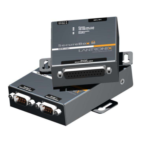
Lantronix SDS1101 User manual

Lantronix

Lantronix SDS1101 User manual

Lantronix WiPort NR User manual

Lantronix

Lantronix WiPort NR User manual

Lantronix UDS1100 User manual

Lantronix

Lantronix UDS1100 User manual

Lantronix I/O 2100 User manual

Lantronix

Lantronix I/O 2100 User manual

Lantronix xDirect-IAP User manual

Lantronix

Lantronix xDirect-IAP User manual

Lantronix EDS-MD EDS-MD4 User manual

Lantronix

Lantronix EDS-MD EDS-MD4 User manual

Lantronix MSS4 User manual

Lantronix

Lantronix MSS4 User manual

Lantronix xport pro User manual

Lantronix

Lantronix xport pro User manual

Lantronix XPort Quick setup guide

Lantronix

Lantronix XPort Quick setup guide

Lantronix xPico XPW100A003-01-B Quick setup guide

Lantronix

Lantronix xPico XPW100A003-01-B Quick setup guide

Lantronix CoBox-Micro User manual

Lantronix

Lantronix CoBox-Micro User manual

Lantronix XPress DR+ Instruction Manual

Lantronix

Lantronix XPress DR+ Instruction Manual

Lantronix MSS100 User manual

Lantronix

Lantronix MSS100 User manual

Lantronix WiBox2100E User manual

Lantronix

Lantronix WiBox2100E User manual

Lantronix SCSxx05 User manual

Lantronix

Lantronix SCSxx05 User manual

Lantronix EDS1100 Installation manual

Lantronix

Lantronix EDS1100 Installation manual

Lantronix UDS1100 User manual

Lantronix

Lantronix UDS1100 User manual

Lantronix xSenso 2100 User manual

Lantronix

Lantronix xSenso 2100 User manual

Lantronix Console Server 800 User manual

Lantronix

Lantronix Console Server 800 User manual

Lantronix EDS4100 User manual

Lantronix

Lantronix EDS4100 User manual

Lantronix SLC8 User manual

Lantronix

Lantronix SLC8 User manual

Lantronix WiBox 2100E User manual

Lantronix

Lantronix WiBox 2100E User manual

Lantronix WiPort User manual

Lantronix

Lantronix WiPort User manual

Popular Server manuals by other brands

HP Tc2120 - Server - 256 MB RAM installation guide

HP

HP Tc2120 - Server - 256 MB RAM installation guide

Lenovo ThinkServer RD230 manual

Lenovo

Lenovo ThinkServer RD230 manual

Avocent CPS810 Installer/user guide

Avocent

Avocent CPS810 Installer/user guide

Dell PowerEdge R6615 Installation and service manual

Dell

Dell PowerEdge R6615 Installation and service manual

FreeWave HT2+ installation guide

FreeWave

FreeWave HT2+ installation guide

GIGA-BYTE TECHNOLOGY G492-Z50 user manual

GIGA-BYTE TECHNOLOGY

GIGA-BYTE TECHNOLOGY G492-Z50 user manual

Lanner HTCA-E400 user manual

Lanner

Lanner HTCA-E400 user manual

Bull NovaScale T840 E2 user guide

Bull

Bull NovaScale T840 E2 user guide

Asus RS740-E70RS24-EG Configuration guide

Asus

Asus RS740-E70RS24-EG Configuration guide

Meinberg LANTIME M300/TCR manual 

Meinberg

Meinberg LANTIME M300/TCR manual 

HP ProLiant SL335s G7 Maintenance and service guide

HP

HP ProLiant SL335s G7 Maintenance and service guide

ZyXEL Communications VANTAGE RADIUS 50 user guide

ZyXEL Communications

ZyXEL Communications VANTAGE RADIUS 50 user guide

Fujitsu PRIMEQUEST 2400E3 General description

Fujitsu

Fujitsu PRIMEQUEST 2400E3 General description

IBM 9040-MR9 manual

IBM

IBM 9040-MR9 manual

IBM 306m - eServer xSeries - 8849 user guide

IBM

IBM 306m - eServer xSeries - 8849 user guide

green hippo Hippotizer Nevis+ quick start guide

green hippo

green hippo Hippotizer Nevis+ quick start guide

IBM 8203-E4A Brochure & specs

IBM

IBM 8203-E4A Brochure & specs

Ruijie Cloud Class RCD6000E V3 Series user manual

Ruijie

Ruijie Cloud Class RCD6000E V3 Series user manual

manuals.online logo
manuals.online logoBrands
  • About & Mission
  • Contact us
  • Privacy Policy
  • Terms and Conditions

Copyright 2025 Manuals.Online. All Rights Reserved.

Assign IP
Caution: The IP address you assign must be within
a valid range, be unique to your network, and be
in the same subnet as your PC.
Note: For the convenience of assigning an IP address
over your Ethernet network, refer to the “Using ARP
and Ping” section of the Installation Guide.
1) Connect a null modem cable between your computer
and the unit’s console port (#1).
2) Open a terminal emulator (e.g., Hyperterminal).
3) Confirm that the configuration parameters are set
as follows: 9600 Baud, 8/N/1, Xon/Xoff flow control.
4) Press the Enter key.
5) Enter any user name.
6) At the local prompt enter: set privileged
7) Enter system for the password.
8) At the local prompt enter:
change server ipadd [xxx.x.x.xx.]
Configure
1) Open a Web browser.
2) Enter the IP address you just assigned into the URL
address field.
3) Confirm that the following screen displays:
4) Click on the Port Properties heading.
The MSS4 network-enables Industrial Automation,
Medical Instruments, modems, and other serial devices.
Each of its four ports can accommodate RS232, RS422, or
RS485 communication.
The MSS4 delivers remote management and data accessi-
bility through its 10/100BASE-T Ethernet port or its
optional 100BASE-FX fiber link port. Its two optional PC
card slots provide flash storage or wireless Ethernet.
This Quick Start explains how to connect, configure, and
troubleshoot your unit. For more detailed information,
refer to the MSS Installation Guide and Reference Manual
on the CD ROM supplied with this product.
Connections
1) Place the MSS4 near your serial devices
2) Connect your Ethernet cable to the unit’s RJ45
Ethernet port.
3) Optionally, connect your full duplex fiber optic Ethernet
cables to the unit’s ST connectors.
Note: If you wish to use the optional Power Terminal
Block, refer to the Installation Guide.
4) Connect power (9 to 30 VDC, 3W maximum).
5) Wait about 30 seconds.
6) Confirm that the Link LED lights up.
7) Confirm that the OK LED is slowly blinking.
8) Note the pin assignments of the terminal blocks
and DB9 connectors:
Power, Serial, Ethernet Connections
MSS4
Quick Start
MSS4
MSS4
serial 4
serial 3
serial 2
serial 1
pccard 1
pc card 2
link
ok
10/100
100 BaseFX
TX RX
serial 1
2
3
4
reset
pc card
1
2
9-30vdc
Ethernet
Optional
Fiber
Computer
Serial Device
Reset
Button Mounting
Bracket
Optional
PC Card
Slots (2)
Power
Terminal
Block
RJ45
Jack
Console
Port
5
1
9
6
RX
TX
DTR
CTS
RTS
DSR
Grd.
1
5
6
9
NC
TX+
RX+
NC
TX-
RX-
7 1
DSR
CTS
RX
Grd.
TX
RTS
DTR
7 1
NC
RX-
RX÷
Grd. TX÷
TX-
NC
RS-485
RS-232
5) Enter System.
6) Click on the Login button.
7) Confirm that the following screen displays:
8) Select a port.
9) Confirm that your serial device(s) on that port match
the serial parameters listed on the screen.
10) Repeat the last two steps for the other ports.
11) Click the Update Port Settings button.
12) Power cycle the unit to reboot.
PC Card Slot Options
The two optional PC card slots accept Type I/II PC cards.
The bottom slot also accepts Type III cards. Neither sup-
ports hot-swapping; rather, you must reboot the unit any
time you insert a PC card. Refer to our web site to deter-
mine the most current PC card technologies we support:
http://www.lantronix.com/products/ds/mssvia/cards
Note: 802.11 wireless networking is enabled by
default. To customize its settings, refer to the
Installation Guide on your CD.
1) Disconnect power.
2) Insert your PC card into a PCMICA slot.
3) Connect power to the unit.
4) Wait about 30 seconds.
5) Confirm that the slot’s green LED is lit.
Install
1) Disconnect power.
2) Disconnect your computer from the unit.
3) Optionally, mount the unit.
4) Connect your serial devices to the unit.
5) Connect power to the unit.
Troubleshoot
All MSS4 Models contain eight LEDs. The two LEDs
labeled PC Card 1 and PC Card 2 are operative only on
PC card-equipped models. For all MSS4 models, refer
to the following table:
For PC card-equipped models, refer to the
following table:
Contact
Questions? Call Lantronix Technical Support
at 800-422-7044 or 949-453-3990.
15353 Barranca Parkway
Irvine, CA 92618, USA
Phone: (949) 453-3990
Fax: (949) 453-3995
www.lantronix.com
not lit not in slot
green ready
green, blinking negotiating 802.11 settings
or memory card not formatted
red failure
red, blinking not supported; can’t be read
yellow initializing in progress
yellow, blinking scanning for 802.11 access point
or initialization problem
PCC LED PC Card
900-232 Rev.A
Serial 1 green serial traffic when blinking
Serial 2 green serial traffic when blinking
Serial 3 green serial traffic when blinking
Serial 4 green serial traffic when blinking
OK yellow network activity
green normal runtime code
Link none no Ethernet connection
green 10BASE-T connection
yellow 100BASE-T or -FX connection
LED Color Meaning