lbx WB-S User manual

WB-S Multifunctional Water Bath Shaker
Please read the User Manual carefully before use, and follow all operating and safety instructions!
user manual
english, español
User manual

2
WB-S Multifunctional Water Bath Shaker
Preface
Thank you for purchasing our Water Bath. Users should read this manual carefully, follow the instructions and
procedures, and beware of all the preventive measures when using this instrument.
Service
If help is needed, you can always contact your dealer or Labbox via www.labbox.com
Please, provide the customer service representative with the following information:
▪Serial number (on the back side)
▪Description of the problem
▪Your contact information
Warranty
This instrument is guaranteed to be free from defects in materials and workmanship under normal use and
service, for a period of 12 months from the date of invoice. The warranty is extended only to the original
purchaser. It shall not apply to any product or parts that have been damaged due to improper installation,
improper connections, misuse, accident or abnormal conditions of operation.
For claim under the warranty, please contact your supplier.

3
1. Safety Instructions
Connect the device to an earthed socket to ensure the safety of the machine
and the experiment. Make sure the voltage is the same as required by the
device.
The use of this instrument in flammable, explosive, poisonous, or highly
corrosive environments or with hazardous substances is forbidden.
Place the incubator on a horizontal, flat, clean, non-slip and stable surface.
Adjust the feet so that the device is leveled.
This item must only be used by qualified staff that has read the instructions
manual and knows how to operate it.
Do not place the device near any heat source. Keep away from high
magnetic fields. Do not put volatile, flammable and explosive materials in
the machine, otherwise it could cause an explosion or a fire.
Non-professionals must not disassemble or repair this machine.
Read the instructions manual before using this device.
·When working, wear the necessary personal protective equipment to avoid the risk of:
-Burns caused by contact with hot surfaces or materials
-Burns caused by splashing and evaporation of liquids
-Intoxication caused by release of toxic or flammable gases
·The device and accessories must be checked prior to every use. Do not use damaged
components.
·Beware of hazards due to:
-Flammable materials or media with a low boiling temperature
-Overfilling of vessels
-Unsafe vessel
·Do not cover the device.
·Do not expose the device to rain, moisture or splashing as this might result in electrical leakage,
short-circuit or electric shock.
·In case the device is let idle or unsupervised, ensure the door is completely closed.
·Unplug by pulling always from the plug. Never pull from the wire.
·Do not connect the power cord to the middle section.

4
·Ensure that the main cable does not touch the surface.
·Do not damage the power cord and always use the specified one. In case of damage, the
power cord must be replaced.
·Do not unplug the power cord during operation.
·Unplug the cord before maintenance, after use, and if the instrument is running abnormally.
·Do not touch the power plug with wet hands.
·Wear gloves when repairing and maintaining the instrument.
Other necessary considerations:
·When touching the inner wall of the door, do it carefully, as it may be hot.
·The internal parameters must be set by the specific management person to prevent the function
of the controller program from being disturbed by an unknown setting.
·The equipment must be placed at least 20cm away from the wall and from any objects.
·Open and close the door gently to prevent damage to the equipment.
·Do not expose the equipment surface to volatile chemicals.
·Keep the equipment clean, both the inside and the outside.
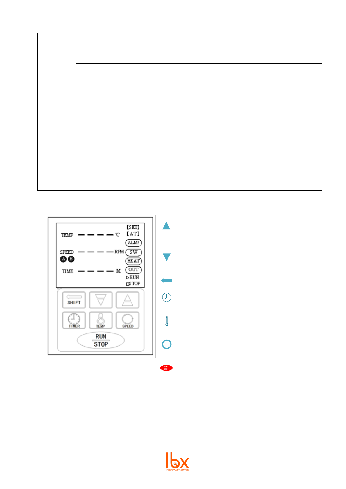
Safety alarms:
·In case of a controller block, Holzer error, busbar under voltage, busbar over voltage or
communication failure, the speed bar will show the fault code and the controller will
automatically stop.
·In case of a temperature or speed alarm, the identifier ALM1 will light up and the buzzer
sound will go off. Stop it by pressing any key.
·When turning off the equipment, always press to stop any ongoing functions before
turning off the device.
·In case of a fault of the temperature sensor or the controller itself, the indicator –will display.
Carefully check the temperature sensor and its wiring.

5
2. Description
2.1. Technical specifications
Mode
Reciprocating oscillation +
thermostatic water bath
Function
Operating Temp Range
RT~100℃
Temperature Resolution Ratio
0.1℃
Temperature Motion
±0.1℃
Temperature Uniformity
±0.2℃
Reciprocal Oscillation Amplitude
16 or 24mm (Ex-factory is 24mm)
Reciprocating Frequency Range
20~200(r/min)
Reciprocating Frequency Accuracy
±1rpm
Structure
Water Tank
Mirror stainless steel
Outer Shell
Cold rolling steel electrostatic
spraying exterior
Upper Cover
Mirror stainless steel
Insulating Layer
Polyurethane
Heater
Stainless Steel Heater
Driving Mode
Crankshaft+ double link + four wheels
Shelf
Mirror stainless steel
Power rating
1.5kW
Controller
Temperature Control Mode
LCD PID Intelligent control
Reciprocating Control Mode
Setting Mode
Touch button setting
Temp. Display Mode
LCD Display
Speed Display Mode
Timer
0~9999 min
Operation Function
·fixed value operation
·timing function
·auto stop
·quick stop-start
Temperature Sensor
Pt100
Speed Sensor
Hoare
Additional Functions
·deviation correction
·menu keys lock
·power-off memory
Device safety
·over-temperature alarm
·menu lock

6
·full water tank or water shortage protection
·motor shaft lock protection
Specificatio
n
Water Tank Size (W*L*H) (mm)
500*310*200
Exterior Size (W*L*H) (mm)
828*360*425
Packing Size (W*L*H) (mm)
908*440*505
Spring Shock Basket Size (mm)
395*250
Shock Basket Largest Single Size
(ml /piece)
100ml*12/250*8/500*6
Inside Volume
31L
Shock Basket Bearing
5kg/layer
Current Rating (50Hz)
AC220V/6.8A
NW/GW (kg)
20/30
Accessories
·water bath flask seat
·tube rack
2.2. Control Keys
-Press to increase the parameter value by one.
Keep pressed to continuously increase the
value.
-Press to reduce the parameter value by one.
Keep pressed to continuously reduce the value.
-Press to navigate through the parameters.
-Press to enter time value setting mode. Press
again to return to home screen.
-Press to enter temperature value setting mode.
Press again to return to home screen.
-Press to enter speed value setting mode. Press
again to return to home screen.
-Press to start running the device functions. Press
again to stop.

7
3. Temperature internal parameter settings mode
3.1. How to use
In order to enter the temperature internal parameter setting mode, the user must introduce the
password. To do that, follow these steps:
1. Press for 3 seconds.
-The screen will display Lc
-The speed area of the screen will display the password value
2. Use to choose the required password value. See password values below.
3. Press to enter the value.
If the password is incorrect, the display will return to the home screen.
If the password is correct, the display will show the temperature internal parameter settings mode.
Then:
1. Press to modify each parameter.
2. Use to choose desired value.
3. Press for 3 seconds to return to the home screen.
If no key is pressed for 1 minute, the display will return to the home screen.
3.2. Internal parameters tables
INDICATOR
NAME
FUNCTION DESCRIPTION
(RANGE)
DEFAULT VALUE
Lc
Password
The password to modify the parameters in this
table is Lc = 3
0
ALH
Upper deviation
over temperature
alarm
IF
THEN
·the alarm light is turned on
·the buzzer calls
·the heating output is disconnected.
(0~20.0℃)
5.0
T
Control cycle
Heating control cycle.
(1~60s) 5
P
Proportional
band
Time proportional adjustment.
(0.1~50.0)
15.0
I
Integration time
The integral function is adjusted.
(1~2000s) 380
d
Differential time
Differential action regulation.
(0~2000s) 100
LT
Floodlight
time
Time the floodlight stays ON every time.
When Lt=0, the delay is invalid and the lights
need to be turned off manually.
(0~9999min)
0
temperature
measurement
temperature
set value
AL
>
+

8
St-
Sterilization lamp
off-delay
Time the sterilization lamp stays ON every time.
When St=0, the delay is invalid and the lights
need to be turned off manually.
(0~9999min)
0
Pb
Temperature
correction
Correction of errors caused by sensor low
temperature measurement.
(-99.9~99.9℃)
0
PL
Slope correction
Correction of errors caused by sensor high
temperature values.
(-999~999) 0
INDICATOR
NAME
FUNCTION DESCRIPTION
FACTORY VALUE
Lc
Password
The password to modify the parameters in this
table is Lc = 9
0
Pon
Power down
memory function
0: OFF –if the power goes off, the controller
will stop working.
1: ON –if the power goes off, when the device
is turned on again it will continue running the
functions it was running when the power went
off.
(0~1)
0
ruT
RUN/STOP
key delay
Time after which the function of the RUN/STOP
button will be effective
(0~10s)
0
nP
Maximum power
output
The maximum power percentage of the heating
output.
(0~100%)
100
Co
Turn off the
heating output
deviation
IF
THEN the heating output is turned OFF.
(0.0~20.0℃)
5.0
SPH
Upper
temperature limit
Upper limit of temperature set point
(0.0~200.0℃)
100.0
Adr
mailing address
The local communication address.
(1~32)
1
INDICATOR
NAME
FUNCTION DESCRIPTION
FACTORY VALUE
Lc
Password
The password to modify the parameters in this
table is Lc = 576
0
rST
Factory reset
0: Do not restore the factory value
1: Restore the factory value. Including:
·internal parameters table 1, 2 and 6
·parameters Fr, DB and dF from
internal parameters table 5
(0~1)
0
actual
temperature
value
temperature
measured
value
Pb
=
_
1000
actual temperature
value
temperature
measured value
-
temperature measured value
PL
×
=
temperature
measurement
temperature
set value
Co
≥
+

9
4. Speed internal parameter settings
4.1. How to use
In order to enter the temperature internal parameter setting mode, the user must introduce the
password. To do that, follow these steps:
4. Press for 3 seconds.
-The screen will display Lc
-The speed area of the screen will display the password value
5. Use to choose the required password value. See password values below.
6. Press to enter the value.
If the password is incorrect, the display will return to the home screen.
If the password is correct, the display will show the temperature internal parameter settings mode.
Then:
4. Press to modify each parameter.
5. Use to choose desired value.
6. Press for 3 seconds to return to the home screen.
If no key is pressed for 1 minute, the display will return to the home screen.
4.2. Internal parameter tables
INDICATOR
NAME
FUNCTION DESCRIPTION
FACTORY VALUE
Lc
Password
The password to modify the parameters in this
table is Lc = 3
0
Pd
Proportional
gain
Speed proportional gain.
(1~100)
10
Id
Integral
coefficient
Speed integral coefficient.
(1~100)
5
InT
Acceleration
time
Time it takes for the motor to accelerate to the
new set speed.
(1~60)
10
dET
Deceleration
time
Time it takes for the motor to decelerate to the
new set speed.
(1~60)
10
SdL
Speed lower
limit
Minimum speed setting
(20~500)
20
SdH
Speed upper
limit
Maximum speed setting
(20~500)
300

10
INDICATOR
NAME
FUNCTION DESCRIPTION
FACTORY VALUE
Lc
Password
The password to modify the parameters in this
table is Lc = 9
0
EAr
Gear ratio
(1.0~10.0)
1.0
PoL
Pole logarithm
of motor
The DC brushless motor is extremely
logarithmic.
(1~32)
4
dIF
Motor rotation
reference
direction
0: clockwise rotation is the positive direction
1: counterclockwise rotation is the positive
direction
(0~1)
0
FdS
Speed
feedback
value
Speed feedback system value
(0.1~10.0)
1.0
FdC
Current
feedback
value
Current feedback system value
(0.1~10.0)
1.0
FrE
Carrier
frequency
Brushless motor carrier frequency
Note: when this parameter is changed, the
controller needs to be restarted.
(5~15)
15
Po
Motor power
Brushless motor power.
Note: this parameter must be adjusted
according to the actual power of the motor.
(1~100)
60
CL
Overflow
multiple
Allowable current multiplier for overcurrent
protection of the motor.
(1.0~10.0)
5.0
Fr
Rotation
direction
selection of
motor
0: The motor only runs in forward rotation.
1: The motor only runs in reverse.
2: The motor can run in both directions.
(0~2)
0
db
Insensitive
display
area
Speed display insensitive area
(0~100)
2
dF
False display
Reservation is invalid
big gear diameter
pinion diameter
EAr
=

11
5. Time internal settings
5.1. How to use
Setting the rotation times
When Fr = 0 or Fr = 1, the motor only runs in one direction, forward or reverse, respectively. In that
case, follow these instructions to set the rotation time:
→the temperature screen will display AT.
1. Press
2. Use to choose the motor running time.
3. Press to enter the value and return to the home screen.
Once the timer goes off, it will make a buzzer sound and display End. Stop it by pressing
any key. To restart the operation, press
Note: when the timer is set to 0, the equipment will run continuously until it is stopped
manually.
When Fr = 2, the motor can alternate between the two rotating directions. To set the different
rotation and stopping times, follow the next instructions:
1. Set the FORWARD rotation time:
→the indicator Fd will show.i. Press
ii. Use to choose the motor forward running time.
iii. Press to enter the value.
2. Set the STOPPING time:
i. Once you press the indicator P will show.
ii. Use to choose the motor stopping time.
iii. Press to enter the value.
3. Set the REVERSE rotation time:
i. Once you press the indicator Rd will show.
ii. Use to choose the motor stopping time.
iii. Press to enter the value and return to the home screen.
Note: the forward, stopping, and reverse rotation times can be selected in minutes. The total
time can be selected in hours and minutes. See below how to select the unit.

12
Modifying the time internal parameters
In order to enter the temperature internal parameter setting mode, the user must introduce the
password. To do that, follow these steps:
1. Press for 3 seconds.
-The screen will display Lc
-The speed area of the screen will display the password value
2. Use to choose the required password value. See password values below.
3. Press to enter the value.
If the password is incorrect, the display will return to the home screen.
If the password is correct, the display will show the temperature internal parameter settings mode.
Then:
1. Press to modify each parameter.
2. Use to choose desired value.
3. Press for 3 seconds to return to the home screen.
If no key is pressed for 1 minute, the display will return to the home screen.
5.2. Internal parameter table
INDICATOR
NAME
FUNCTION DESCRIPTION
FACTORY VALUE
Lc
Password
The password to modify the parameters in this
table is Lc = 3
0
ndT
Timing mode
selection
0: when the timer goes off, stop the speed only,
not the temperature.
1: when the timer goes off, stop the speed AND
the temperature.
2: The timer starts to count after reaching the
temperature set value. When the timer goes off,
stop the speed only, not the temperature.
3: The timer starts to count after reaching the
temperature set value. When the timer goes off,
stop the speed AND the temperature.
Note: This parameter cannot be modified during
operation. If you do that, the timer will restart.
(0~3)
1
Hn
Total time
units
0: Time is measured in minutes –mis displayed.
1: Time is measured in hours –his displayed.
Note: This parameter cannot be modified during
operation.
(0~1)
0
SPd
Constant
temperature
deviation
IF
THEN the equipment enters the constant
temperature state.
(0.1~100.0℃)
0.5
temperature
measurement
temperature
set value
SPd
≥
-

13
EST
Time end
prompting
time
Time for which the buzzer sound is on when the
timer goes off.
Note: when EST=9999, the buzzer sound time is
indefinite
(0~9999s)
60
rT
Total time
error
correction
Correct the total timing error
6. System self-tuning
When the temperature control effect is not ideal, a system self-tuning can be carried out where the
equipment will automatically configurate its PID parameters. To do that, follow the next instructions:
during 6 seconds →enter the self-tuning state selection1. Press
-The temperature section will display AT.
-The speed display section will display OFF.
2. Use to select ON or OFF. Select ON to activate the self-tuning function.
to enter →self-tuning will begin.
3. Press
-The AT indicator will flash until self-tuning ends. Once it stops flashing, the new
parameters will be automatically saved.
To abort the process at any time, press for 6 seconds or turn off the controller.
Note: during this process, the setting keys do not work.
10
actual time (s)
run time (s)
actual time (s)
-
correction
value
×
=

14
7. Wiring diagram
1. Power out by AC24V Transformer, regardless of plus-minus when connection
2. MTZSH5-C1005 Series without lighting function (without 19, 20 terminal)
3. With MTZB Type, the PT100 Sensor can be connected to the 21/22/23 terminal; MTZSH Type without 21/22/23
terminal, the PT100 sensor needs to be connected behind the display panel
Note: thick wire and thin wire must not
be mistakenly connected, otherwise the
motor and controller will be damaged.

15
8. General faults and troubleshooting
Failure phenomenon
Fault analysis
Troubleshooting
Equipment is ON but the
display is not.
Power supply is not connected
Check if the power outlet has power
The power plug is not
plugged in
Check the contact between the power
plug and the socket
The power switch is not on
Turn on the power switch on the right
side of the instrument
Damage of the fuse on the
box
Replacement of a power fuse with the
same specification
Sharp drop in the water
level in the sink
Continuous high temperature
operation causes rapid
evaporation
Refill the water tank in time before too
much water evaporates
Drain valve leak
Repair or replace the drain valve
Water tank seepage
Notify the factory to get the it repaired
Instability of the shaking
plate
The instrument is not stable
Adjust the foot of the instrument to
stabilize the instrument
External object at the bottom
of the plate
Remove the object
Control circuit fault
Notify the factory to get it repaired
The measured temperature
is higher than the set
temperature and the system
enters the high-temperature
alarm state.
The water level is too low
Increase the water level so that it is
higher than the heating tube and the
sensor
The instrument has not yet
entered the state of constant
temperature
Wait for a moment and check again
Temporary high-temperature
phenomenon
Correct the temperature setting
Heater anomaly
Notify the factory to get it repaired
The measured temperature
is lower than the set
temperature and the system
enters the low-temperature
alarm state.
The lid of the is not properly
closed and heat is constantly
exuding the instrument
Close the lid properly and do not open
it too frequently.
The instrument has not yet
entered the state of constant
temperature
Wait for a moment and check again
Heater anomaly
Notify the factory to get it repaired
The noise of the instrument is
too loud
The instrument is not placed
properly
Adjust the foot of the instrument to
stabilize the instrument
The flask clamp fixing screw is
loose
Remove the flask and the plate and
tighten the screw
Shake plate loosening
Tighten the screws at the four corners of
the plate
Bump on the bottom of the
plate due to an object
Remove the object
Mechanical failure
Notify the factory to get it repaired

16
Manual de usuario
WB-S Baño de agua con agitación
Introducción
Gracias por comprar nuestro baño con agitación. Los usuarios deben leer este manual atentamente, seguir las
instrucciones y los procedimientos, y estar informados de todas las precauciones antes de usar el equipo.
Servicio
Cuando necesite ayuda, puede contactar con su distribuidor o con Labbox a través de www.labbox.com
Por favor proporcione al personal de Atención al Cliente la siguiente información:
▪Número de serie del equipo (en el panel trasero o debajo del equipo)
▪Descripción del problema
▪Sus datos de contacto
Garantía
Este equipo está garantizado contra cualquier defecto en los materiales y de fabricación bajo un uso normal,
por un período de 12 meses a partir de la fecha de la factura. La garantía se extiende solamente al
comprador original. La garantía no se aplicará a ningún producto o piezas que se hayan dañado a causa de
una instalación incorrecta, de conexiones incorrectas, de un uso erróneo, de accidente o de condiciones
anormales de operación.
Para las reclamaciones bajo garantía, por favor póngase en contacto con su proveedor.

17
1. Instrucciones de seguridad
Conecte el equipo a un enchufe con puesta a tierra para asegurar la
seguridad del aparato y del experimento. Asegúrese de que el voltaje de
la fuente es el mismo especificado por el aparato.
Este equipo no debe ser usado en ningún entorno inflamable, explosivo,
tóxico o corrosivo, ni con sustancias peligrosas.
Coloque la incubadora en una superficie horizontal, lisa, limpia,
antideslizante y estable. Ajuste la base de manera que quede equilibrada.
Este producto debe ser usado únicamente por personal cualificado y que
haya leído las instrucciones de funcionamiento.
No coloque el equipo cerca de ninguna fuente de calor. Manténgalo
alejado de campos magnéticos. No ponga sustancias volátiles, inflamables ni
explosivas en el aparato ya que podrían causar una explosión o un
incendio.
El personal no cualificado no debe desmontar ni reparar este producto.
Lea el manual de instrucciones antes de usar este equipo.
•Mientras trabaje, use el equipo de protección personal necesario para evitar el riesgo de:
-Quemadas por el contacto con superficies o materiales a alta temperatura
-Quemadas por salpicadas o vaporación de líquidos
-Intoxicación por la emisión gases tóxicos
•El equipo y sus accesorios deben ser revisados antes de cada uso. No utilice componentes
dañados.
•Preste atención a los riesgos causados por:
-Materiales inflamables o sustancias con un punto de ebullición bajo
-Llenado excesivo de los recipientes
-Recipientes inseguros
•No cubra el equipo.
•No exponga el equipo a lluvia, humedad o salpicaduras ya que esto podría provocar una
fuga de electricidad, un cortocircuito o una descarga eléctrica.
•En caso de que el equipo sea dejado funcionar sin supervisión, asegúrese de que la puerta
está bien cerrada.
•Al desenchufar el equipo, tire de la clavija, no del cable.
•No conecte la toma de corriente a la sección central.
•Asegúrese de que el cable principal no toca la superficie del equipo.

18
•No dañe el cable y siempre use el especificado. En caso de daños, el cable debe ser
reemplazado.
•No desconecte el equipo de la toma de corriente mientras está en funcionamiento.
•Desconecte el equipo siempre después de ser usado, antes de mantenimiento y en caso de
funcionamiento irregular.
•No toque el enchufe con las manos mojadas.
•Lleve guantes durante la reparación y el mantenimiento del equipo.
Otras consideraciones necesarias:
•Los parámetros internos deben ser ajustados por el personal a cargo del equipo pare evitar
que el funcionamiento se vea afectado por un ajuste desconocido.
•El equipo debe colocarse al menos a 20cm de la pared y de cualquier objeto.
•Abra y cierre la puerta con cuidado para evitar daños al equipo.
•Tenga cuidado al tocar la parte interior de la puerta ya que podría estar caliente.
•No exponga la superficie del equipo a sustancias volátiles.
•Mantenga tanto el interior como el exterior del equipo limpios.
Alarmas de seguridad:
·En caso de un bloqueo del controlador, error Holzer, bajo voltaje, alto voltaje o fallo de
comunicación, la sección de velocidad mostrará el código del error y el controlador se
detendrá automáticamente.
·En caso de una alarma de temperatura o velocidad, se mostrará el identificador ALM1 y
sonará el sonido de alarma. Para pararlo, presione cualquier botón.
·Antes de apagar el equipo, presione siempre para detener cualquier función en
marcha.
·En caso de un fallo con el sensor de temperatura o el controlador, se mostrará el símbolo - .
Compruebe el sensor de temperatura y su cableado.

19
2. Descripción
2.1. Especificaciones técnicas
Modo
Oscilación + baño de agua termostático
Function
Rango de la temperatura
RT~100℃
Precisión de la temperatura
0.1℃
Desviación de la temperatura
±0.1℃
Uniformidad de la temperatura
±0.2℃
Amplitud de la oscilación
16 or 24mm (Ex-factory is 24mm)
Rango de frecuencias
20~200(r/min)
Desviación de la frecuencia
±1rpm
Estructura
Depósito de agua
Acero inoxidable espejado
Carcasa exterior
Acero laminado en frío con pulverización
electrostática
Tapa superior
Acero inoxidable espejado
Aislante térmico
Poliuretano
Calefactor
Calefactor de acero inoxidable
Motor
Cigüeñal + doble link + cuatro ruedas
Placa
Acero inoxidable espejado
Potencia nominal
1.5kW
Controller
Modo de control de la temperatura
Control inteligente LCD PID
Modo de control de la oscilación
Modo de ajuste
Botón táctil
Modo de muestra de la temperatura
Pantalla LCD
Modo de muestra de la velocidad
Temporizador
0~9999min
Función de operación
·operación de valor fijo
·función de temporizador
·auto stop
·quick stop-start
Sensor de temperatura
Pt100
Sensor de velocidad
Hoare
Funciones adicionales
·corrección de la desviación
·bloqueo de los botones del menú
·memoria de apagado

20
Seguridad del equipo
·alarmas de temperatura
·bloqueo del menú
·protección de tanque de agua lleno y de
falta de agua
·protección de bloqueo del eje del motor
Especifica-
ciones
Medidas de la cámara interior
(W*L*H) (mm)
500*310*200
Medidas exteriores (W*L*H) (mm)
828*360*425
Medida del embalaje (W*L*H) (mm)
908*440*505
Medidas del cesto de amortiguación
(mm)
395*250
Medidas máximas del cesto de
amortiguación (ml/pieza)
100*12/250*8/500*6
Volumen interior
31L
Capacidad de carga del cesto de
amortiguación ca
5kg/layer
Capacidad de corriente (50Hz)
AC220V/6.8A
NW/GW (kg)
20/30
Accesorios
·soporte para recipientes en el tanque de
agua
·gradilla para tubos de ensayo
2.2. Botones de control
-Presione para aumentar el valor del parámetro en
una unidad.
-Presione para reducir el valor del parámetro en una
unidad.
-Presione para navegar por los parámetros.
-Presione para entrar el modo de modificación del
valor de tiempo. Vuelva a presionar para volver a
la pantalla inicial.
-Presione para entrar el modo de modificación del
valor de temperatura. Vuelva a presionar para
volver a la pantalla inicial.
-Presione para entrar el modo de modificación del
valor de velocidad. Vuelva a presionar para volver
a la pantalla inicial.
-Presione para poner en marcha las funciones del
equipo. Vuelva a presionar para detenerlas.
Table of contents
Languages:
Other lbx Laboratory Equipment manuals
Popular Laboratory Equipment manuals by other brands

Thermo Scientific
Thermo Scientific 1267 Series operating manual

Diesse
Diesse CHORUS SPECIFIC IgE Instructions for use

Thermo Scientific
Thermo Scientific 88870001 operating manual

Altronix
Altronix NetWay Series installation guide

Clifton
Clifton SW 30 H manual

Helmer Scientific
Helmer Scientific QuickThaw DH2 Operation manual

Araknis Networks
Araknis Networks AN-ACC-INJ-POE-30W quick start guide

REITEL
REITEL STEAMY MINI operating instructions

Heidolph
Heidolph UNIMAX 2010 instruction manual

CURIOSIS
CURIOSIS Celloger Mini instruction manual

Carestream
Carestream Dryview 6850 user guide

Microscan
Microscan Mobile Hawk quick start guide