Leader LV 7770 User manual

LV 7770 MULTI RASTERIZER
(Digital Audio Unit)
LV 7770 OP70 16CH DIGITAL AUDIO ADAPTER
LV 5770SER42 ANALOG AUDIO
FUNCTION MENU EXPLANATIONS

TABLE OF CONTENTS
1. INTRODUCTION ........................................................................................................ 1
1.1 About This Manual .................................................................................................................. 1
1.2 About Terminology Used in this Manual.................................................................................. 1
2. AUDIO DISPLAY ........................................................................................................ 2
2.1 Configuring Measurement Signal Settings.............................................................................. 3
2.1.1 Selecting the Signal to Measure ...................................................................................... 3
2.1.2 Selecting the Channels to Measure ................................................................................. 4
2.1.3 Selecting the Number of Measurement Channels........................................................... 4
2.1.4 Selecting the Stream........................................................................................................ 5
2.2 Selecting the Display Mode .................................................................................................... 5
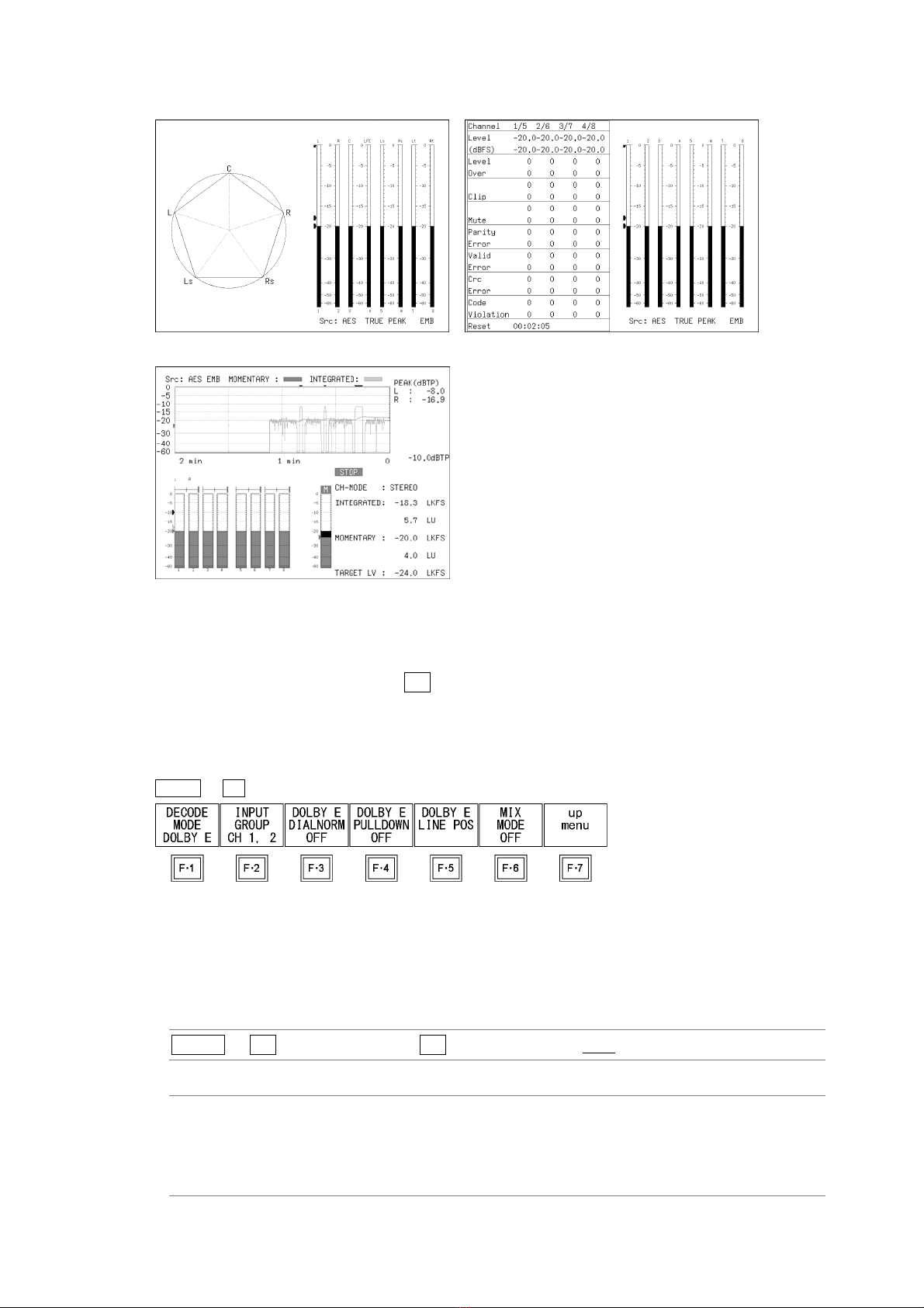
2.3 Configuring the DolbySettings (Option).................................................................................. 6
2.3.1 Selecting the Signal to Measure ...................................................................................... 6
2.3.2 Selecting the Channel to Decode .................................................................................... 7
2.3.3 Turning Dialog Normalization On and Off ........................................................................ 9
2.3.4 Turning Pulldown On and Off........................................................................................... 9
2.3.5 Frame Location Indicator Display .................................................................................. 10
2.3.6 Selecting the Listening Mode......................................................................................... 12
2.3.7 Turning Prologic On and Off .......................................................................................... 12
2.3.8 Selecting the DRC ......................................................................................................... 12
2.3.9 Turning Mix Mode On and Off........................................................................................ 12
3. METER DISPLAY ..................................................................................................... 13
3.1 Selecting the Scale............................................................................................................... 13
3.2 Setting the Response Model................................................................................................. 13
3.3 Setting the Peak Hold ...........................................................................................................14
3.4 Setting the Reference Level.................................................................................................. 14
3.5 Mapping Channels................................................................................................................15
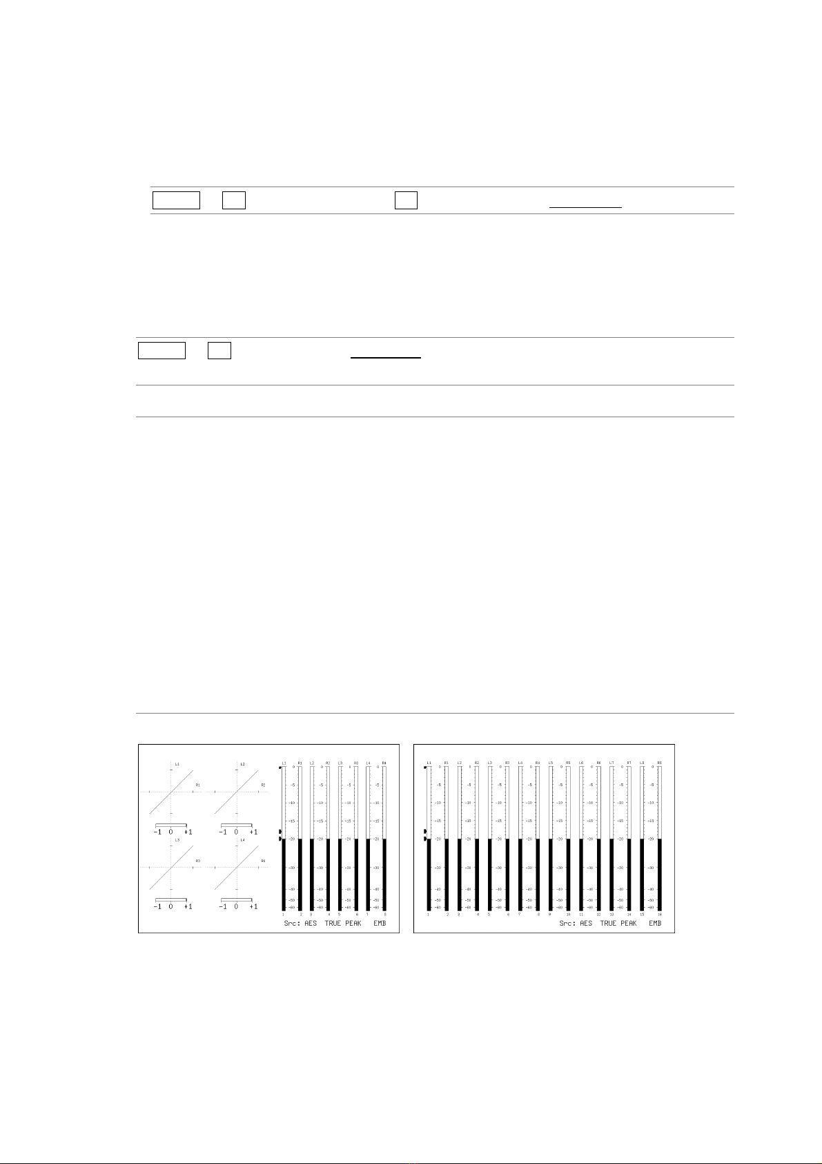
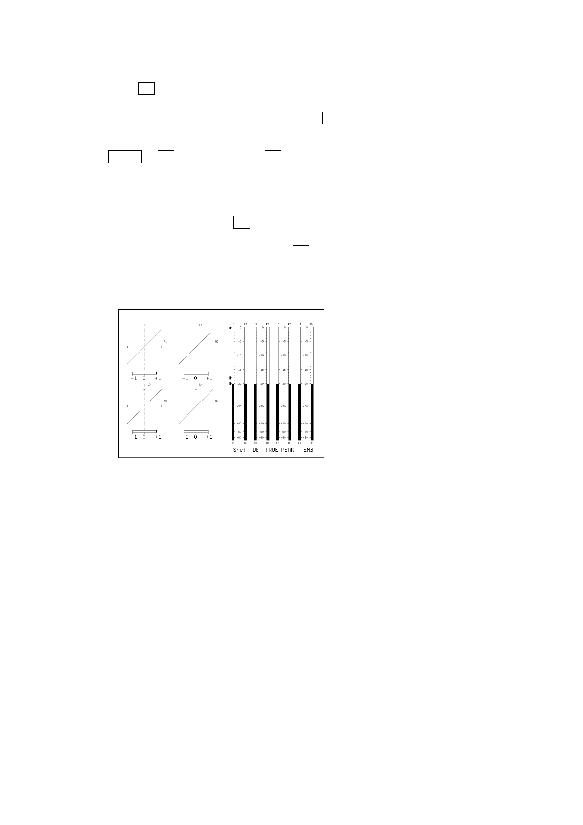
4. LISSAJOUS DISPLAY .............................................................................................. 16
4.1 Adjusting the Lissajous Curve Intensity ................................................................................ 16
4.2 Adjusting the Scale Intensity................................................................................................. 16
4.3 Selecting the Lissajous Curve Display Format...................................................................... 17
4.4 Selecting the Scale Display Format ...................................................................................... 18
4.5 Setting the Lissajous Curve Gain.......................................................................................... 18
4.6 Mapping Channels................................................................................................................19
5. SURROUND DISPLAY ............................................................................................. 22
5.1 Adjusting the Surround Waveform Intensity .......................................................................... 22
5.2 Adjusting the Scale Intensity................................................................................................. 22
5.3 Selecting the Surround Display Format ................................................................................ 22
5.4 Setting the Surround Waveform Gain ................................................................................... 23

5.5 Mapping Channels................................................................................................................24
6. AUDIO STATUS DISPLAY........................................................................................ 25
6.1 Audio Status Display Explanation ......................................................................................... 25
6.2 Event Log Display................................................................................................................. 27
6.2.1 Event Log Explanation................................................................................................... 28
6.2.2 Starting Event Logging................................................................................................... 30
6.2.3 Deleting the Event Log .................................................................................................. 30
6.2.4 Selecting the Overwrite Mode........................................................................................ 30
6.2.5 Saving to a USB Memory Device................................................................................... 31
6.3 Metadata Display (Option) .................................................................................................... 33
6.3.1 Dolby E Metadata Display.............................................................................................. 33
6.3.2 Dolby E EBI Metadata Display....................................................................................... 33
6.3.3 Dolby Digital Metadata Display ...................................................................................... 34
6.3.4 Dolby Digital EBI Metadata Display ............................................................................... 35
6.4 Displaying the Channel Status .............................................................................................. 35
6.5 Displaying User Bits.............................................................................................................. 36
6.6 Configuring Error Detection Settings .................................................................................... 37
6.7 Resetting Errors.................................................................................................................... 37
7. LOUDNESS DISPLAY .............................................................................................. 38
7.1 Loudness Display Explanation.............................................................................................. 38
7.2 Selecting the Measurement Time ......................................................................................... 41
7.3 Clearing the Loudness Measurement ................................................................................... 41
7.4 Starting and Stopping Measurements ................................................................................... 42
7.5 Selecting the Scale............................................................................................................... 42
7.6 Configuring Loudness Settings ............................................................................................. 43
7.7 Saving to a USB Memory Device.......................................................................................... 47
7.8 Remote Control..................................................................................................................... 50
8. CONFIGURING THE HEADPHONE SETTING ........................................................ 52
8.1 Adjusting the Volume ............................................................................................................52
8.2 Selecting the Channels to Output ......................................................................................... 53
8.3 Setting the AUX Channel (Option) ........................................................................................ 53
9. MENU TREE ............................................................................................................ 54

1. INTRODUCTION
1
1. INTRODUCTION
1.1 About This Manual
This manual explains the audio menus that are available on an LV 7770 when the LV 7770
OP70 (16CH DIGITAL AUDIO ADAPTER), LV 5770SER42 (ANALOG AUDIO), or Dolby option
is installed. For details on how to operate the LV 7770, see the LV 7770 (MULTI RASTERIZER)
Instruction Manual.
1.2 About Terminology Used in this Manual
• Single Input Mode
This refers to the mode in which the SIM key is off. Press the A and B keys to switch
between measuring the signal that is being applied to SDI INPUT A and the signal that is
being applied to SDI INPUT B, respectively.
• Simul mode
This refers to the mode in which the SIM key is on. The signals that are being applied to
SDI INPUT A and SDI INPUT B are measured simultaneously.
• About the Input Format
The input formats are written in this manual as shown below.
Table 1-1 Input format
Name Description
HD dual link HD-SDI dual link
3G-B (2map) 3G-SDI level B 2mapping
• Underline (_)
Underlined options indicate the default values.

2. AUDIO DISPLAY
2
2. AUDIO DISPLAY
To display audio waveforms, press AUDIO.
You can measure the audio signals that are embedded in SDI signals or the audio signals that
are applied to the audio I/O connectors.
For HD dual link signals, only the audio signal embedded in link A is measured.
Figure 2-1 Audio display
• Src
"Src" (in the lower right of the screen) displays the following items in order from the left.
Table 2-1 Explanation of Src
Display Indication Explanation See
AES Dolby off
DE Dolby E
DD Dolby Digital
2.3.1
AES/ DE Dolby E mix mode
1. Dolby
AES/ DD Dolby Digital mix mode
2.3.9
2. Meter response model TRUE PEAK, PPM(I), PPM(II),
VU+PPM(I), VU+PPM(II)
- 3.2
EMB Embedded audio
AES External digital audio
3. Measured signal
ANA Analog audio
2.1.1

2. AUDIO DISPLAY
3
• Menu
Use the audio menu—which is displayed when you press the AUDIO key—to configure the
audio display settings.
AUDIO →
Figure 2-2 Audio menu
2.1 Configuring Measurement Signal Settings
To configure measurement signal settings, press F•1 SOURCE SELECT on the audio menu.
You can use this menu to set the signal to measure and the channels to measure.
AUDIO →F•1 SOURCE SELECT →
Figure 2-3 SOURCE SELECT menu
2.1.1 Selecting the Signal to Measure
To select the signal to measure, follow the procedure below.
Procedure
AUDIO →F•1 SOURCE SELECT →F•1 INPUT SELECT: SDI / EXT DIGI / EXT ANA
Settings
SDI: The audio signal embedded in the SDI signal is measured. “EMB” is
displayed in the lower right of the screen.
EXT DIGI: The digital audio signal that is applied to a DIGITAL AUDIO IN/OUT
connector on the rear panel is measured. “AES” is displayed in the lower right
of the screen.
This option cannot be selected if GROUP A and GROUP B (OP70) under
REAR PANEL SETUP in the system settings have both been set to OUTPUT.
Simul mode is not supported. Perform this measurement with the SIM key
LED turned off.
EXT ANA: The analog audio signal that is applied to an ANALOG AUDIO connector on
the rear panel is measured. “ANA” is displayed in the lower right of the screen.
This option can be selected when an LV 5770SER42 is installed in the LV
7770 and ANALOG AUDIO under REAR PANEL SETUP in the system
settings is set to INPUT.
Simul mode is not supported. Perform this measurement with the SIM key
LED turned off.

2. AUDIO DISPLAY
4
2.1.2 Selecting the Channels to Measure
To select the channels to measure, follow the procedure below.
Procedure
AUDIO →F•1 SOURCE SELECT →F•2 1ST GRP SELECT / F•3 2ND GRP SELECT
→F•2 ACH GRP SELECT / F•3 BCH GRP SELECT
→F•2 1ST GRP PCM / F•3 2ND GRP PCM
→F•2 CHANNEL SELECT
→F•2 PCM SELECT
→F•5 NUMBER of CHANNELS
The channels that you can select vary depending on the F•1 INPUT SELECT, input mode,
and F•5 NUMBER of CHANNELS settings as shown in the following table.
Table 2-2 Selecting the channels to measure
INPUT
SELECT
Input
Mode
NUMBER of
CHANNELS Measurement Channels Notes
8CH F•2 1ST GRP SELECT ( 1 / 2 / 3 / 4 )
F•3 2ND GRP SELECT ( 1 / 2 / 3 / 4 )
Single
input mode
16CH Ch 1 to 16
SDI
Simul mode 8CH F•2 ACH GRP SELECT ( 1 / 2 / 3 / 4 )
F•3 BCH GRP SELECT ( 1 / 2 / 3 / 4 )
1: Ch 1 to 4
2: Ch 5 to 8
3: Ch 9 to 12
4: Ch 13 to 16
- 8CH Ch D1 to D8 -SDI
(Dolby) Mix mode 16CH Ch 1 to 8, ch D1 to D8 -
- 8CH F•2 CHANNEL SELECT
( GROUP A / GROUP B(OP70) )
GROUP A: Ch A1 to A8
GROUP B: Ch B1 to B8
EXT DIGI
- 16CH (OP70) Ch A1 to A8, ch B1 to B8 -
- 8CH Ch D1 to D8 -EXT DIGI
(Dolby) Mix mode 16CH F•2 PCM SELECT
( GROUP A / GROUP B(OP70) ), ch D1 to D8
GROUP A: Ch A1 to A8
GROUP B: Ch B1 to B8
EXT ANA - 8CH Ch 1 to 8 -
2.1.3 Selecting the Number of Measurement Channels
In one input mode, if F•1 INPUT SELECT is set to SDI or EXT DIGI and DECODE MODE
is set to OFF, to select the number of measurement channels, follow the procedure below.
For other settings, the number of measurement channels are fixed as shown in the above
table, and you cannot change it.
It may take up to approximately 7 seconds to switch the number of measurement channels.
For information on the DECODE MODE setting, see section 2.3.1, “Selecting the Signal to Measure.”
Procedure
AUDIO →F•1 SOURCE SELECT →F•5 NUMBER of CHANNELS: 8CH / 16CH

2. AUDIO DISPLAY
5
2.1.4 Selecting the Stream
When the input signal is 3G-B (2map), to select the stream to measure, follow the
procedure below.
Procedure
AUDIO →F•1 SOURCE SELECT →F•6 STREAM SELECT: STREAM 1 / STREAM 2
2.2 Selecting the Display Mode
To select the display mode, follow the procedure below.
It may take up to approximately 7 seconds to switch the display mode.
Procedure
AUDIO →F•2 DISPLAY MODE: LISSAJOU / METER / SURROUND / STATUS /
LOUDNESS
Settings
LISSAJOU: The Lissajous curves are displayed. During 8-channel measurement, audio
meters are also displayed. During 16-channel external digital audio
measurement, channels B1 to B8 are displayed as CH9 to CH16.
METER: The audio meters are displayed. This option cannot be selected during
8-channel measurement. During digital audio measurement, channels B1
to B8 are displayed as CH9 to CH16.
SURROUND: The surround display is shown on the left side of the screen, and the audio
meter is displayed on the right side of the screen.
This option cannot be selected in simul mode or 16-channel measurement.
STATUS: The status is displayed. During 8-channel measurement, audio meters are
also displayed. During 16-channel external digital audio measurement,
channels B1 to B8 are displayed as CH9 to CH16.
LOUDNESS: The loudness values are displayed on a chart, on a meter, and as values.
This option cannot be selected in simul mode or 16-channel measurement.
DISPLAY MODE = LISSAJOU DISPLAY MODE = METER

2. AUDIO DISPLAY
6
DISPLAY MODE = SURROUND DISPLAY MODE = STATUS
DISPLAY MODE = LOUDNESS
Figure 2-4 Selecting the display mode
2.3 Configuring the Dolby Settings (Option)
To configure Dolby settings, press F•6 DOLBY SETUP on the audio menu.
This menu is displayed when the Dolby option is installed in the LV 7770 and INPUT SELECT
is set to SDI or EXT DIGI.
For information on the INPUT SELECT setting, see section 2.1.1, “Selecting the Signal to Measure.”
AUDIO →F•6 DOLBY SETUP →
Figure 2-5 DOLBY SETUP menu
2.3.1 Selecting the Signal to Measure
To select the signal to measure, follow the procedure below.
Procedure
AUDIO →F•6 DOLBY SETUP →F•1 DECODE MODE: OFF / DOLBY E / DOLBY D
Settings
OFF: Dolby signals are not measured.
DOLBY E: Dolby E signals are measured. This option cannot be selected in simul mode.
DOLBY D: Dolby Digital signals are measured. This option cannot be selected in simul
mode.

2. AUDIO DISPLAY
7
2.3.2 Selecting the Channel to Decode
When F•1 DECODE MODE is set to DOLBY E or DOLBY D, to select the channel to
decode, follow the procedure below.
CH 9,10 to CH15,16 can be selected when F•6 MIX MODE is set to ON.
Procedure
AUDIO →F•6 DOLBY SETUP →F•2 INPUT GROUP: CH 1, 2 / CH 3, 4 / CH 5, 6 /
CH 7, 8 / CH 9,10 / CH11,12 / CH13,14 / CH15,16
●When INPUT SELECT Is Set to SDI and MIX MODE Is Set to OFF
Channels selected using F•2 INPUT GROUP are decoded and displayed as channels
D1 to D8.
The channels that you can select with F•2 INPUT GROUP are the channels in the group
selected with 1ST GRP SELECT and 2ND GRP SELECT.
For information on the 1ST GRP SELECT and 2ND GRP SELECT setting, see section 2.1.2, “Selecting
the Channels to Measure.”
Figure 2-6 EMB Dolby display

2. AUDIO DISPLAY
8
●When INPUT SELECT Is Set to SDI and MIX MODE Is Set to ON
The left half of the display shows the embedded audio signals selected with 1ST GRP
PCM and 2ND GRP PCM.
The right half shows channels D1 to D8, which are the decoded signals of the channels
selected using F•2 INPUT GROUP.
In the meter display, cyan ■marks are displayed above non-PCM signals.
For information on the 1ST GRP PCM and the 2ND GRP PCM setting, see section 2.1.2, “Selecting the
Channels to Measure.”
Figure 2-7 EMB Dolby display (mix mode)
●When INPUT SELECT Is Set to EXT DIGI and MIX MODE Is Set to OFF
Channels selected using CHANNEL SELECT and F•2 INPUT GROUP are decoded and
displayed as channels D1 to D8.
For information on the CHANNEL SELECT setting, see section 2.1.2, “Selecting the Channels to
Measure.”
Figure 2-8 AES Dolby display

2. AUDIO DISPLAY
9
●When INPUT SELECT Is Set to EXT DIGI and MIX MODE Is Set to ON
The left half shows external audio channels selected with PCM SELECT.
The right half shows channels D1 to D8, which are the decoded signals of the channels
selected using F•2 INPUT GROUP. Here F•2 INPUT GROUP CH 1, 2 to CH 7, 8
correspond to channels A1 to A8; and CH 9,10 to CH15,16 correspond to channels B1 to
B8.
In the meter display, cyan ■marks are displayed above non-PCM signals.
For information on the PCM SELECT setting, see section 2.1.2, “Selecting the Channels to Measure.”
Figure 2-9 AES Dolby display (mix mode)
2.3.3 Turning Dialog Normalization On and Off
When F•1 DECODE MODE is set to DOLBY E, to turn the dialog normalization on and off,
follow the procedure below.
Procedure
AUDIO →F•6 DOLBY SETUP →F•3 DOLBY E DIALNORM: ON / OFF
2.3.4 Turning Pulldown On and Off
When F•1 DECODE MODE is set to DOLBY E, to turn the pulldown on and off, follow the
procedure below.
Procedure
AUDIO →F•6 DOLBY SETUP →F•4 DOLBY E PULLDOWN: ON / OFF

2. AUDIO DISPLAY
10
2.3.5 Frame Location Indicator Display
When INPUT SELECT is set to SDI and F•1 DECODE MODE is set to DOLBY E, the frame
location value can be displayed with an indicator.
The indicator is shown in the lower left of the screen, and the value is indicated with a bar
and ▲mark. These are normally shown in cyan, but when the value exceeds the
specified threshold, they turn red.
For information on the INPUT SELECT setting, see section 2.1.1, “Selecting the Signal to Measure.”
Figure 2-10 Frame location indicator display
To show the indicator, follow the procedure below to set INDICATE to ON.
Procedure
AUDIO →F•6 DOLBY SETUP →F•5 DOLBY E LINE POS
Figure 2-11 DOLBY E LINE POS tab

2. AUDIO DISPLAY
11
• INDICATE
Turns the frame location indicator display on and off.
• SELECT
Set the frame location threshold value.
The threshold value when VALID or IDEAL is selected varies depending on the format as
shown below.
If you select CUSTOM, you can specify a value between 8 and 105.
Table 2-3 Frame location threshold value
VALID IDEAL
Format Lower limit Upper limit Lower limit Upper limit
625i/50 8 30 11 13
525i/59.94 12 26 13 16
1080i/60 18 52 21 26
1080i/59.94 18 48 21 26
1080i/50 13 53 19 23
1080p/60 35 104 42 52
1080p/59.94 35 95 42 52
1080p/50 26 105 37 46
1080p/30 18 52 21 26
1080p/29.97 18 48 21 26
1080p/25 13 53 19 23
1080p/24 11 98 25 29
1080p/23.98 11 98 25 29
720p/60 23 69 28 35
720p/59.94 23 63 28 35
720p/50 17 70 25 31
720p/30 12 35 14 18
720p/29.97 12 32 14 18
720p/25 9 35 13 16
720p/24 8 65 17 19
720p/23.98 8 65 17 19

2. AUDIO DISPLAY
12
2.3.6 Selecting the Listening Mode
When F•1 DECODE MODE is set to DOLBY D, to select the listening mode, follow the
procedure below.
Procedure
AUDIO →F•6 DOLBY SETUP →F•3 DOLBY D LISTENIN: FULL / EX / 3stereo /
PHANTOM / STEREO / MONO
2.3.7 Turning Prologic On and Off
When F•1 DECODE MODE is set to DOLBY D, to turn the prologic on and off, follow the
procedure below.
Procedure
AUDIO →F•6 DOLBY SETUP →F•4 DOLBY D PROLOGIC: ON / OFF
2.3.8 Selecting the DRC
When F•1 DECODE MODE is set to DOLBY D, to select the DRC (Dynamic Range
Control), follow the procedure below.
Procedure
AUDIO →F•6 DOLBY SETUP →F•5 DOLBY D DRC: BYPASS / LINE / RF
2.3.9 Turning Mix Mode On and Off
When F•1 DECODE MODE is set to DOLBY E or DOLBY D, to turn the mix mode on and
off, follow the procedure below.
Mix mode is a feature that simultaneously displays the audio signal before decoding and
the Dolby signal after decoding. For details, see section 2.3.2, “Selecting the Channel to
Decode.”
Procedure
AUDIO →F•6 DOLBY SETUP →F•6 MIX MODE: OFF / ON

3. METER DISPLAY
13
3. METER DISPLAY
To configure meter display settings, press F•3 METER SETUP on the audio menu.
You can set the meter's scale, the response model, and the reference level.
AUDIO →F•3 METER SETUP →
Figure 3-1 METER SETUP menu
3.1 Selecting the Scale
To select the meter's scale, follow the procedure below.
When MAG on the LOUDNESS SETUP menu is set to ON, the scale of the loudness chart is
set to -18 to 9 (LK/LU) in reference to the target level, regardless of the setting specified here.
Procedure
AUDIO →F•3 METER SETUP →F•1 DYNAMIC RANGE: -60dBFS / -90dBFS / MAG
Settings
-60dBFS: The scale of the meter, loudness chart, and loudness meter is set to -60 to 0
(dBFS/LKFS/LUFS).
-90dBFS: The scale of the meter, loudness chart, and loudness meter is set to -90 to 0
(dBFS/LKFS/LUFS).
MAG: The scale of the meter is set to the level specified by F•3 REF dBFS ± 3 dB.
The scale of the loudness chart and loudness meter is set to -60 to 0
(LKFS/LUFS).
3.2 Setting the Response Model
To select the meter's response model, follow the procedure below. The selected response
model is indicated in the lower right of the display.
Procedure
AUDIO →F•3 METER SETUP
→F•2 RESPONSE: TRUEPEAK / PPM / VU
→F•3 PPM MODE: PPM(I) / PPM(II) (when RESPONSE is set to PPM)
→F•3 PEAK METER: TRUE / PPM(I) / PPM(II) (when RESPONSE is set to VU)

3. METER DISPLAY
14
The response model details are shown in the following table.
Table 3-1 Response model settings
F•2 RESPONSE F•3 Display Indication Delay Time(*1) Return Time(*2) Average Time
TRUEPEAK - TRUE PEAK 0 msec 1.7 sec -
PPM(I) PPM(I) 10 msec 1.7 sec -PPM
PPM(II) PPM(II) 10 msec 2.8 sec -
TRUE VU+TRUE - - 300 msec
PPM(I) VU+PPM(I) - - 300 msec
VU
PPM(II) VU+PPM(II) - - 300 msec
*1 The amount of time it takes for the meter to show -20 dBFS when a -20 dBFS/1 kHz sine-wave signal is
applied with no input preceding it.
*2 The amount of time it takes for the meter to show -40 dBFS when a -20 dBFS/1 kHz sine-wave signal is
removed from the input.
3.3 Setting the Peak Hold
When F•2 RESPONSE is set to VU, to set the peak hold time, follow the procedure below.
The unit is seconds. You can set the value in 0.5-second steps.
Press the function dial (F•D) to return the setting to its default value (0.5).
Procedure
AUDIO →F•3 METER SETUP →F•4 PEAK HOLD: 0.0 to 0.5 to 5.0 / HOLD
3.4 Setting the Reference Level
To set the meter reference level, follow the procedure below.
• OVER
The value that you set here is displayed as a red arrow at the corresponding level on the
meter. If the audio level is greater than or equal to this value, a Level Over is counted on
the audio status screen.
• WARNING
The value that you set here is displayed as a yellow arrow at the corresponding level on the
meter. The levels above the yellow arrow are displayed in red. The levels below the arrow
are displayed in yellow.
• REF
The value that you set here is displayed as a green arrow at the corresponding level on the
meter. The levels above the green arrow are displayed in yellow. The levels below the
arrow are displayed in green.
Procedure
AUDIO →F•3 METER SETUP →F•5 LEVEL SETTING
→F•1 OVER dBFS: -40.0 to 0.0
→F•2 WARNING dBFS: -40.0 to -18.0 to 0.0
→F•3 REF dBFS: -40.0 to -20.0 to 0.0

3. METER DISPLAY
15
3.5 Mapping Channels
When DISPLAY MODE is set to METER, to select the channels to assign to the L and R axes
of the audio meter and Lissajous display, follow the procedure below. For details, see section
4.6, “Mapping Channels.”
For information on the DISPLAY MODE setting, see section 2.2, “Selecting the Display Mode.”
Procedure
AUDIO →F•3 METER SETUP →F•6 CHANNEL MAPPING

4. LISSAJOUS DISPLAY
16
4. LISSAJOUS DISPLAY
To configure Lissajous settings, press F•4 LISSAJOU SETUP on the audio menu.
You can configure Lissajous curve and scale settings.
This setting is available when F•2 DISPLAY MODE is set to LISSAJOU.
AUDIO →F•2 DISPLAY MODE to select LISSAJOU →F•4 LISSAJOU SETUP →
Figure 4-1 LISSAJOU SETUP menu
4.1 Adjusting the Lissajous Curve Intensity
To adjust the Lissajous curve intensity, follow the procedure below.
Press the function dial (F•D) to return the setting to its default value (0).
Procedure
AUDIO →F•4 LISSAJOU SETUP →F•1 LISSAJOU INTEN: -8 to 0 to 7
4.2 Adjusting the Scale Intensity
To adjust the intensity of the Lissajous and meter scales, follow the procedure below.
Press the function dial (F•D) to return the setting to its default value (4).
Procedure
AUDIO →F•4 LISSAJOU SETUP →F•2 SCALE INTEN: -8 to 4 to 7

4. LISSAJOUS DISPLAY
17
4.3 Selecting the Lissajous Curve Display Format
To select the Lissajous curve display format, follow the procedure below.
Regardless of the display format that you select, the channels set with F•6 CHANNEL
MAPPING are displayed.
The correlation meter shown below the Lissajous waveform indicates the phase difference
between the two signals. A reading of +1 indicates that the signals are in-phase, a reading of
-1 indicates that the signals are 180 ° out of phase, and a reading of 0 indicates that the
signals are not correlated.
Procedure
AUDIO →F•4 LISSAJOU SETUP →F•3 DISPLAY: MULTI / SINGLE
Settings
MULTI: Eight channels of Lissajous waveforms and eight channels of audio meters are
displayed or 16 channels of Lissajous waveforms are displayed.
SINGLE: Two channels of Lissajous waveforms and eight channels of audio meters are
displayed.
This option cannot be selected in simul mode.
DISPLAY = MULTI DISPLAY = SINGLE
Figure 4-2 Selecting the Lissajous curve display format
Other manuals for LV 7770
1
This manual suits for next models
2
Table of contents
Other Leader Measuring Instrument manuals

Leader
Leader LV 5770 User manual

Leader
Leader LV5300A User manual

Leader
Leader LF5 User manual

Leader
Leader LV 7380 User manual

Leader
Leader LE 8682 User manual

Leader
Leader LV 5480 Parts list manual

Leader
Leader LT 4446 User manual

Leader
Leader D11.06.010 User manual

Leader
Leader LV 7770 User manual

Leader
Leader Search User manual