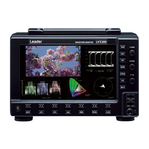
Leader LV5300 User manual

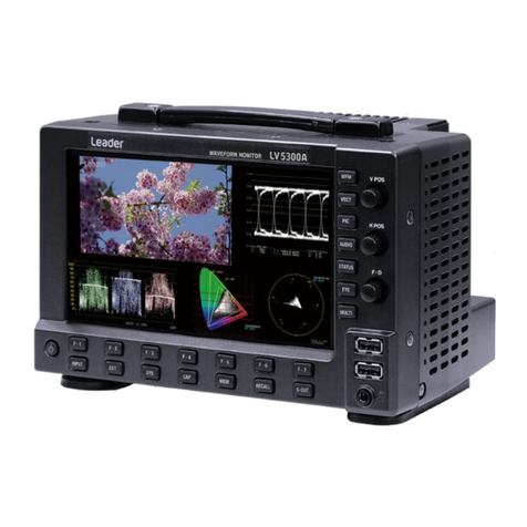
LV5300 / LV5350 / LV7300
WAVEFORM MONITOR / RASTERIZER
LV7300-SER01 SDI INPUT
LV7300-SER02 SDI INPUT / EYE
LV5300-SER11 / LV5350-SER11 BATTERY ADAPTER V MOUNT
LV5300-SER12 / LV5350-SER12 BATTERY ADAPTER QR GOLD
LV5300-SER20 / LV5350-SER20 / LV7300-SER20AUDIO
LV5300-SER21 / LV5350-SER21 / LV7300-SER21CLOSED CAPTION
LV5300-SER22 / LV5350-SER22 / LV7300-SER22CIE
LV5300-SER23 / LV5350-SER23 / LV7300-SER23HDR
LV5300-SER24 / LV5350-SER24 / LV7300-SER24TSG
LV5300-SER25 / LV5350-SER25 / LV7300-SER25FOCUS ASSIST
LV5300-SER26 / LV5350-SER26 / LV7300-SER26LAYOUT
LV5300-SER27 / LV5350-SER27 / LV7300-SER27TALLY
LV5300-SER28 / LV5350-SER28 / LV7300-SER284K
Instruction Manual
Thank you for purchasing.
Please carefully read this instruction manual and the included "GENERAL SAFETY SUMMARY".
Please use the product safely.

TABLE OF CONTENTS
GENERAL SAFETY SUMMARY .................................................................................. I
1. INTRODUCTION............................................................................................ 1
1.1 Scope of Warranty.................................................................................................... 1
1.2 Operating Precautions............................................................................................... 1
1.2.1Maximum Allowable Input Voltage........................................................................ 1
1.2.2 Mechanical Shock............................................................................................... 2
1.2.3 Electrostatic Damage.......................................................................................... 2
1.2.4 Warming Up...................................................................................................... 2
1.2.5 About Standby Mode .......................................................................................... 2
1.2.6 Backup ............................................................................................................. 2
1.2.7 About the LCD Panel (LV5300/LV5350) ................................................................. 2
1.3 About Trademarks and Licenses ................................................................................. 3
1.4 Terminology Used in This Manual................................................................................ 3
2. PRODUCT CONFIGURATION............................................................................ 5
2.1 Lineup .................................................................................................................... 5
2.2 Hardware Options .................................................................................................... 5
2.3 Software Options ..................................................................................................... 6
2.4 Items Sold Separately............................................................................................... 6
3. SPECIFICATIONS........................................................................................... 7
3.1 General................................................................................................................... 7
3.2 Features ................................................................................................................. 8
3.3 Specifications ......................................................................................................... 10
3.3.1 SDI Video Formats and Standards (SER01/SER02/SER24/SER28) ............................10
3.3.2 SDI Audio Formats and Standards (SER01/SER02/SER20) ......................................14
3.3.3 SDI Input Connector (SER01/SER02/SER28) ........................................................14
3.3.4 SDI Output Connector (SER01/SER02/SER24/SER28) ............................................15
3.3.5 External Reference Input....................................................................................15
3.3.6 Monitor Output Connector (LV7300) ....................................................................16
3.3.7 Headphone Output............................................................................................17
3.3.8 Control Connectors............................................................................................ 17
3.3.9 Front Panel ......................................................................................................18
3.3.10 Capturing ........................................................................................................ 19
3.3.11 TSG (SER24/SER28)..........................................................................................20
3.3.12 Presets ............................................................................................................21
3.3.13 Display ............................................................................................................21
3.3.14 Video Signal Waveform Display ...........................................................................23
3.3.15 Vector Display ..................................................................................................25
3.3.16 Picture Screen ..................................................................................................26
3.3.17 Superimpose Display (SER21).............................................................................26

3.3.18 CINELITE Display ..............................................................................................28
3.3.19 CINELITE Advanced Display................................................................................30
3.3.20 CINEZONE Display ............................................................................................30
3.3.21 Focus Assist (SER25)......................................................................................... 31
3.3.22 CIE Chromaticity Diagram Display (SER22)........................................................... 31
3.3.23 HDR Display (SER23) ........................................................................................32
3.3.24 Audio Display ...................................................................................................33
3.3.25 Status Display ..................................................................................................36
3.3.26 Eye Pattern (LV5300/LV7300-SER02) ..................................................................41
3.3.27 Jitter Display (LV5300/LV7300-SER02) ................................................................43
3.3.28 Tally Display .....................................................................................................44
3.3.29 Camera ID Display ............................................................................................44
3.3.30 General Specifications........................................................................................45

I
GENERAL SAFETY SUMMARY
■Read This before Using the Instrument
This instrument should only be used by persons with sufficient knowledge of electronics who
thoroughly understand the contents of this manual.
This instrument is not designed or manufactured for households or ordinary consumers.
If unqualified personnel are to use the instrument, be sure the instrument is handled under the
supervision of qualified personnel (those who have electrical knowledge). This is to prevent the
possibility of personal injury or damage to the instrument.
■Note about Reading This Manual
The contents of this manual contain specialized terminology and may be difficult to understand. If
you have any questions about the contents of this manual, please contact your local LEADER agent.
■Symbols and Terms
The following symbols and terms are used in this instruction manual and on the instrument to
indicate important warnings and notes.
<Symbol>
This symbol appears in this instruction manual and on the instrument to
indicate an area where improper handling could result in personal injury,
damage to the instrument, or malfunction of the instrument or devices
connected to it.
When you encounter this symbol on the instrument, be sure to refer to the
information in this instruction manual that corresponds to the area that the
symbol marks.
<Term>
Ignoring the precautions that this term indicates could lead to death or
serious injury.
<Term>
Ignoring the precautions that this term indicates could lead to personal injury
or damage to the instrument.

II
GENERAL SAFETY SUMMARY
Read the warnings and information below thoroughly to avoid death, personal injury, and damage and
deterioration of the instrument.
■Warnings Concerning the Case and Panels
Do not remove the instrument's case or panels for any reason. Touching the internal components
of the instrument could lead to fire or electric shock.
Also, do not allow foreign materials, such as liquids, combustible matter, and metal, to enter the
instrument. Turning the instrument on when such materials are inside it could lead to fire, electric
shock, damage to the instrument, or some other accident.
■Installation Environment
●Operating Temperature Range
Use this instrument in a 0 to 40 °C environment. Using the instrument with its vents blocked or
in a high temperature environment could lead to fire.
Drastic changes in temperature, such as might be caused by moving the instrument between
two rooms with different temperatures, can damage the instrument by causing condensation to
form within it. If there is a possibility that the instrument has condensation within it, wait for
approximately 30 minutes before turning on the power.
●Operating Humidity Range
Use this instrument in an environment whose relative humidity is 85 % or less where there is no
threat of condensation forming.
Also, do not operate this instrument with wet hands. Doing so could lead to electric shock or fire.
●Do Not Operate in an Explosive Atmosphere
Using this instrument in an environment where flammable gases, explosive gazes, or steam is
emitted or stored could lead to an explosion or fire. Do not use the instrument in such an
environment.
●Do Not Insert Foreign Materials
Do not insert foreign materials, such as metal and flammable objects, through the vents or allow
liquid to enter the instrument. Such acts can lead to fire, electric shock, damage to the
instrument, or some other accident.
■If You Notice Something Wrong during Operation
If you notice smoke, fire, a strange smell, or something else that is wrong with the instrument
while you are operating it, stop operation immediately. Failing to do so could lead to fire. Turn OFF
the power switch, and remove the power cord from the outlet. After making sure that fire has not
spread anywhere, contact your local LEADER agent.

III
GENERAL SAFETY SUMMARY
■Warnings Concerning the Power Source
Do not use a power source with a voltage other than the rated power source voltage for the
instrument. Doing so could lead to fire.
Confirm the voltage of the power source before you connect the power cord to it.
Only use a power source whose frequency is 50/60 Hz.
Use a power cord that is appropriate for the voltage of the power source. Also, use a power cord
that meets the safety standards of the country that you are using it in.
Using a power cord that does not meet the standards could lead to fire. If the power cord is
damaged, stop using it, and contact your local LEADER agent. Using a damaged power cord could
lead to electrical shock or fire.
When removing the power cord from the power outlet, do not pull on the cord. Pull from the plug.
■Warnings Concerning Grounding
The instrument has a ground terminal to protect the user and the instrument from electric shock.
Ensure that the product is properly grounded for safe operation.
■Warnings Concerning the Panel
Sections of the panel are made out of glass. If the glass breaks, the broken glass may lead to
injury. Do not apply a strong shock to the panel, cut it with sharp metal, or damage it in any similar
manner.
■Cautions Concerning the Input and Output Connectors
To avoid damaging the instrument, only apply signals to the input connectors that conform to the
specifications in this instruction manual. Do not short or apply external voltage to the output
connectors. Doing so could damage the instrument.
■Cautions Concerning the Ethernet Port
When you are connecting the instrument to the communication provider's equipment, connect to
the Ethernet port through a hub that is authorized for use in the country that you are using the
instrument in.

IV
GENERAL SAFETY SUMMARY
■Calibration and Repairs
This instrument has been carefully examined at the factory to ensure that its performance is in
accordance with the standards. However, because of factors such as parts wearing out over time, the
performance of the instrument may degrade. To ensure stable performance, we recommend that
you have the instrument calibrated regularly. Also, if the instrument malfunctions, repairs are
necessary. For repairs and calibration, contact your local LEADER agent.
■Routine Maintenance
When you clean the instrument, remove the power plug from the outlet.
Do not use thinner or benzene when you clean the instrument's case, panels, or knobs. Doing so
could lead to paint chipping and the corrosion of plastic components. To clean the case, panels, and
knobs, use a soft cloth with mild detergent, and wipe gently. While cleaning, make sure that foreign
materials, such as water and detergent, do not enter the product. If liquid or a metal object enters
into the instrument, fire or electric shock may result.
■About the European WEEE Directive
This instrument and its accessories are subject to the European WEEE Directive.
Follow the applicable regulations of your country or region when discarding this
instrument or its accessories. Follow the EU Battery Directive when discarding the
batteries that you removed from this instrument.
(WEEE stands for Waste Electrical and Electronic Equipment.)
Follow the warnings and precautions that have been listed in this section to use the instrument correctly
and safely. Precautions are also contained in various other sections of this instruction manual. To use the
instrument correctly, be sure to follow those precautions as well.
If you have any questions or comments about this instruction manual, please contact your local LEADER
agent.

1. INTRODUCTION
1
1. INTRODUCTION
Thank you for purchasing this LEADER instrument. To use this instrument safely, read this
instruction manual thoroughly, and make sure that you know how to use the instrument properly.
If some point about the operation of this instrument is still unclear after you have read this
instruction manual, refer to the contact information on the back cover of the manual to contact
LEADER, or contact your local LEADER agent.
After you have finished reading this manual, keep it in a convenient place so that you can refer to
it when necessary.
1.1 Scope of Warranty
This LEADER instrument has been manufactured under the strictest quality control guidelines.
LEADER shall not be obligated to furnish the following free services during the warranty period.
1. Repair of malfunction or damages resulting from fire, natural calamity, or improper voltage
applied by the user.
2. Repair of a product that has been improperly repaired, adjusted, or modified by personnel
other than a factory-trained LEADER representative.
3. Repair of malfunctions or damages resulting from improper use.
4. Repair of malfunctions caused by devices other than this instrument.
5. Repair of malfunctions or damages without the presentation of a proof of purchase or receipt
bill for the instrument.
This Warranty is valid only in Japan.
1.2 Operating Precautions
1.2.1 Maximum Allowable Input Voltage
The maximum signal voltage that can be applied to the input connectors is indicated below.
Do not apply excessive voltage to the connectors. Doing so may damage the device or lead to
injury.
Table 1-1 Maximum allowable input voltage
Input Connector
Maximum Allowable Voltage
Main unit
EXT REF
±5 V (DC + peak AC)
Main unit
REMOTE
0 to 5 VDC
SER01
SDI INPUT
±2 V (DC + peak AC)
SER02
SDI INPUT
±2 V (DC + peak AC)

1. INTRODUCTION
2
1.2.2 Mechanical Shock
This instrument contains sensitive components, so it may be damaged if it is dropped or
otherwise exposed to a strong shock.
1.2.3 Electrostatic Damage
Electronic components can be damaged by static discharge. Static electricity can build up in
the core wire of a coaxial cable. Before connecting a coaxial cable to an I/O connector of the
instrument, short the core wire of the cable with the external conductor.
1.2.4 Warming Up
To ensure more accurate measurements, turn ON the instrument approximately 30 minutes
before you intend to use it to allow its internal temperature to stabilize.
1.2.5 About Standby Mode
Even if you press the power switch to turn off this instrument, the instrument remains in
standby mode as long as the power cord is connected to the outlet. In standby mode, some of
the internal circuits operate and may generate heat. Unless necessary, keep the power cord
disconnected from the outlet.
1.2.6 Backup
This instrument has a last-memory feature. When you turn the power on, the instrument
starts with the panel settings that were in use the last time that it was turned off. If the backup
battery is out of power, the message "The last memory feature is disabled." will appear, and
this last-memory feature will no longer work.
To continually use the last-memory feature, we recommend that you replace the backup
battery with a new one every five years after you purchase the instrument. You cannot replace
the backup battery yourself. For details, contact your nearest LEADER agent.
1.2.7 About the LCD Panel (LV5300/LV5350)
There may be a small number of pixels in the LCD panel that do not light or are always on. Note
that this is not a malfunction.
The LCD panel supports a large number of video signals. SDI input signals are displayed
asynchronously on the LCD. Therefore, images may appear to flicker on the waveform and
picture displays.
In addition, the input SDI signal is temporarily stored in frame memory and is loaded by using
the LCD display synchronization signal—which is not synchronized with the input SDI signal.
Therefore, because frame skip—which skips over frames in the memory—and frame
repeat—which reads the same frames of the memory twice—occur, the image may appear to
flicker.
(An external sync signal can be used to synchronize the LCD to the input signal.)

1. INTRODUCTION
3
1.3 About Trademarks and Licenses
The company and product names in this document are trademarks or registered trademarks of
their respective holders.
DynaFont is a registered trademark of DynaComware Taiwan Inc.
This product uses open source software under the GNU General Public License
(http://www.gnu.org/copyleft/gpl.html).
If you need the source code covered by the GNU General Public License, CONTACT YOUR LOCAL
LEADER AGENT.
[Notes]
1. Leader does not provide warranty or support for the software covered by the GNU General
Public License.
2. Alteration and distribution of this program shall be performed under your responsibility.
3. The expense of Leader distributing the software to you shall be borne by you.
1.4 Terminology Used in This Manual
●SER**
LV5300-SER**, LV5350-SER** and LV7300-SER** are referred to as SER**.
●Single Input Mode
This refers to the mode in which on the INPUT menu, F•7 DISPLAY is set to SINGLE.
It is a mode for measuring a single input signal.
●Simul Mode
This refers to the mode in which on the INPUT menu, F•7 DISPLAY is set to SIMUL.
It is a mode for measuring multiple input signals simultaneously.
●Multi-screen Display
This refers to the mode in which the MULTI key is on.
●Underlining (_)
Underlined options indicate the default values.

1. INTRODUCTION
4
●Input Formats and Link Systems
The following names are used for the input formats and link systems.
Multi link may be used as a collective term to refer to dual link and quad link.
Table 1-2 Input formats and link systems
Name
Description
Link System
SD
SD-SDI
Single link
HD
HD-SDI
Single link
3G-A
3G-SDI level A
Single link
3G-B-DL
3G-SDI level B dual link mapping
Single link
12G
12G-SDI TYPE 1
Single link
3G
Collective name for 3G links
-
3G-B
Collective name for 3G-B-DL and 3G-B-DS
-
4K
Collective name for 12G
-

2. Product Configuration
5
2. PRODUCT CONFIGURATION
2.1 Lineup
LV5300 WAVEFORM MONITOR Built-in LCD
LV5350 WAVEFORM MONITOR Built-in LCD
LV7300 RASTERIZER External monitor type
2.2 Hardware Options
This instrument operates as a measuring instrument by installing hardware options.
To replace or add hardware options, contact your local LEADER agent. You cannot install or
uninstall units.
Table 2-1 Hardware options
Model Name
Lineup
Function
LV5300 LV5350 LV7300
SDI INPUT - Standard
support
LV7300-SER01 SD, HD, 3G SDI input (*1)
SDI INPUT/EYE Standard
support
- LV7300-SER02 SD, HD, 3G SDI input and eye pattern display (*1)
BATTERY ADAPTER V MOUNT LV5300-SER11 LV5350-SER11 - V mount type battery adaptor (*2)
BATTERY ADAPTER QR GOLD LV5300-SER12 LV5350-SER12 - QR gold type battery adaptor (*2)
*1 The LV7300 requires the LV7300-SER01, or LV7300-SER02 to be installed.
The LV7300-SER01 and LV7300-SER02 cannot be installed in the instrument at the same time.
*2 The LV5300-SER11 and LV5300-SER12 cannot be installed in the instrument at the same time.
The LV5350-SER11 and LV5350-SER12 cannot be installed in the instrument at the same time.

2. Product Configuration
6
2.3 Software Options
The following software options (sold separately) can be installed in the instrument.
If you want to obtain a software option, provide your local LEADER agent with the instrument’s
MAC address (see the LICENSE tab) and serial number (see the rear panel). We will issue a
license key.
When you receive the license key, install the option. Each instrument requires a unique license
key. You cannot use the same key for multiple instruments.
Table 2-2 Software options
Model Name
Lineup
Function
LV5300 LV5350 LV7300
AUDIO LV5300-SER20 LV5350-SER20 LV7300-SER20 Audio display function
CLOSED CAPTION LV5300-SER21 LV5350-SER21 LV7300-SER21 Japanese closed caption, EIA-608, 708, TELETEXT
CIE LV5300-SER22 LV5350-SER22 LV7300-SER22 CIE Chromaticity Diagram Display function
HDR LV5300-SER23 LV5350-SER23 LV7300-SER23 HDR measurement function
TSG LV5300-SER24 LV5350-SER24 LV7300-SER24 SDI signal generation function (*1)
FOCUS ASSIST LV5300-SER25 LV5350-SER25 LV7300-SER25 Focus assist display function
LAYOUT LV5300-SER26 LV5350-SER26 LV7300-SER26 Customized layout function
TALLY LV5300-SER27 LV5350-SER27 LV7300-SER27 ID, iris, tally display function
4K LV5300-SER28 LV5350-SER28 LV7300-SER28 4K video signal support function
*1 You need the LV5300-SER28 to output 4K patterns on the LV5300-SER24.
You need the LV5350-SER28 to output 4K patterns on the LV5350-SER24.
You need the LV7300-SER28 to output 4K patterns on the LV7300-SER24.
2.4 Items Sold Separately
LV5300, LV5350, LV7300
LV7290 Remote controller
AC adaptor
LV5350
LR2530 Rack Mount Adapters
LR2535 Blank Panels
LV7300
LR2731 Rack Mount Adapters
LR2732 Rack Mount Adapters

3. SPECIFICATIONS
7
3. SPECIFICATIONS
3.1 General
The LV5300 WAVEFORM MONITOR, LV5350 WAVEFORM MONITOR, and LV7300 RASTERIZER
are integrated media measuring and monitoring devices that support various video signals and
audio signals. A built-in LCD type and a rasterizer type for use with an external monitor are
available, so you can choose the model appropriate for your installation location.
The LV5300, LV5350, and LV7300 integrate waveform display technologies, measurement
technologies, and monitoring technologies that Leader has accumulated over the years to
provide both high functionality and superb operability.
In terms of video signals, these instruments support a variety of SDI signals up to 12G-SDI. The
video signal waveform display, vector display, picture display, and eye pattern display enable
measurements and quality control of various video signals. The status display allows you to view
various error statuses and system stability in the form of event logs and long-term charts.
In terms of audio signals, these instruments support digitally embedded audio signals in SDI.
Level display, Lissajous display, status display, and so on are available.
In addition to the keys and knobs available on conventional models, these instruments can be
controlled through a USB mouse, the touch panel (*1), and on the LV7300, a set of dedicated
keys for frequently used camera adjustment menus.
Moreover, a rich lineup of options is available in addition to these powerful functions and
operability. Through the combination of these options, these instruments can be used in the
measurement, monitoring, and evaluation of video and audio signals in a wide variety of
applications including (1) broadcast station master monitoring applications for the integrated
monitoring of video and audio signals, (2) monitoring applications for monitoring the quality of
transmission signals, (3) studio sub and post production applications for controlling the video
signal levels, and (4) broadcast equipment compliance applications for determining whether
video and audio signals comply with appropriate standards.
*1 The LV7300 requires a touch-panel type external monitor to be connected to the main unit. The touch
panel interface on the external monitor is connected to the LV7300’s USB port. The video interface on
the external monitor is connected to the LV7300s monitor output connector.
LEADER does not guarantee that all touch panel type monitors will work with the LV7300.

3. SPECIFICATIONS
8
3.2 Features
●Support for a Variety of SDI Signal Inputs
The abundant video signal input options enable measurement and monitoring of SDI signals.
In terms of audio signals, SDI embedded audio is supported. The supported audio format is
L-PCM.
●Superb Operability
Operability was prioritized in the design of these instruments. You can use the best control
interface according to your liking or situation. In addition to the conventional keys and knobs
on the front panel, you can control the instrument remotely using a USB mouse. Further, the
LV5300 and LV5350 have a 7-inch full-HD touch panel. The LV7300 can be connected to a USB
touch panel interface of a touch-panel monitor. These interfaces allow intuitive control and
configuration through touch operation.
●Compact
While providing high flexibility through various options and high functionality for various
situations, the LV5300 and LV5350 are 3U half-rack size and the LV7300 1U full-rack size.
●4K Video Format (SER28)
In addition to SD-SDI, HD-SDI, 3G-SDI single link, 12G-SDI single link are supported. These
cover SDI signals from SD video format to HD video format and even 4K video format.
●Transmission Quality Analysis Function
Signal analysis functions have been enhanced based on the SDI signal measurement
technology that Leader has cultivated over the years. Other enhancements have been made to
various transmission error monitoring, external sync phase difference display, lip sync
measurement (SER20), SDI signal frequency deviation measurement function, equivalent
cable length meter function, and the ancillary data analysis function, which has become more
important with the introduction of 4K video signals.
●Video Analysis Functions
Numerous types of displays are available for the various video signals such as the video signal
waveform display, vector display, picture display, 5-bar display, and CIE chromaticity diagram
display (SER22). In addition, quality control (QoE) functions for video signals are available
including freeze error, black error, and gamut error detection functions. Detected errors can be
recorded in event logs.
●Audio Analysis Functions (SER20)
For audio signals, level meter display is possible on audio signals embedded in SDI.
The SER20 AUDIO option allows Lissajous display, Surround display and detection of mute and
clip errors. Detected errors can be recorded in event logs.
●Eye Pattern Display (LV5300/LV7300-SER02/SER28) (*1)
Eye pattern display and jitter display, which are physical layer measurements of SDI signals
from SD-SDI to 12G-SDI, are possible. These physical layer measurements can be performed
using cursors or performed automatically. Measurements can be exported via a network.

3. SPECIFICATIONS
9
●Closed Caption Decode Display Function (SER21)
Japanese closed captions, English closed captions, TELETXT, and OP47 embedded in SDI
signals can be decoded and displayed.
●External Sync Signal Input
The phase difference and synchronization states of SDI video signals can be shown graphically
based on an external reference sync signal (black burst, tri-level sync).
●Customizable Layout (SER26)
Video signal waveforms, vector waveforms, picture, and other items of input video signals can
be laid out freely in the sizes of your choice.
●SDI Signal Generation Function (SER24/SER28)
The simple SDI signal generator supports HD-SDI to 12G-SDI. For the pattern, you can select
the HD multiformat color bar, the 4K multiformat color bar, or the flat field pattern, which
allows you to select any level. You can also overlay a moving box or insert embedded audio.
●Screen Capture Feature
A screen capture feature, which captures the entire display as still-image data, is available. Not
only can captured data be displayed on the instrument, but it can also be compared with an
input signal or saved to a USB memory device as bitmap data for viewing on a PC.
●Time Code Display
The timecodes embedded in SDI signals can be displayed. The timecode can also be used as
the timestamp in the event log.
●External Remote Connector
A contact terminal can be used to load presets, switch the input signal, and transmit alarms.
●Ethernet Port
By connecting the Ethernet interface to a PC, you can control the LV5300, LV5350, and LV7300
remotely over TELNET, transfer files over FTP, control the LV5300, LV5350, and LV7300
remotely and detect errors over SNMP, and control the LV5300, LV5350, and LV7300 over
HTTP. You can also connect to the separately-sold LV7290 REMOTE CONTROLLER.
●HDR (SER23)
Level monitoring is possible on HLG and PQ defined in ITU-R BT.2100 as well as
S-Log3-compatible HDR signals. Level control is possible based on the estimated brightness
(nits, cd/m2) of a display taking the OOTF into consideration. Video signal waveform display
supports IRE scale as well as HDR scale. On CINEZONE display, the SDR area is displayed in
monochrome, while the HDR area is displayed using colors corresponding to the brightness.
This makes it easy to view the brightness distribution in the HDR area.
●Focus Assist (SER25)
A new focusing algorithm based on nonlinear super-resolution technology has been developed,
allowing highly sensitive focusing even on low-contrast images that were difficult to be focused
in on in the past. You can select the sensitivity according to the image scene.
*1 Only SDI INPUT 1 supports the eye pattern display.
*2 LEADER does not guarantee the operation on all HDMI monitors.

3. SPECIFICATIONS
10
3.3 Specifications
3.3.1 SDI Video Formats and Standards (SER01/SER02/SER24/SER28)
Table 3-1 SD video signal formats and standards
Color System
Quantization
Image
Field Frequency/Scanning
Compliant Standard
YCBCR4:2:2 10 bit
720×487
59.94 /I
SMPTE ST 259
720×576
50 /I
Table 3-2 HD video signal formats and standards
Color System
Quantization
Image
Frame (Field) Frequency/Scanning
Compliant Standard
YCBCR4:2:2 10 bit 1280×720 60/59.94/50/30/29.97/25/24/23.98 /P SMPTE ST 292-1
SMPTE ST 296
1920×1080
60/59.94/50 /I
SMPTE ST 274
SMPTE ST 292-1
30/29.97/25/24/23.98 /P
30/29.97/25/24/23.98 /PsF
Table 3-3 3G-A video signal formats and standards
Color System
Quantization
Image
Frame (Field) Frequency/Scanning
Compliant Standard
YCBCR4:2:2 10 bit 1920×1080 60/59.94/50 /P SMPTE ST 274
SMPTE ST 425-1
48/47.95 /P
-
2048×1080 60/59.94/50/48/47.95 /P SMPTE ST 425-1
SMPTE ST 2048-2
12 bit 1920×1080
60/59.94/50 /I
SMPTE ST 274
SMPTE ST 425-1
30/29.97/25/24/23.98 /P
30/29.97/25/24/23.98 /PsF
2048×1080
30/29.97/25/24/23.98 /P
SMPTE ST 425-1
SMPTE ST 2048-2
30/29.97/25/24/23.98 /PsF
YCBCR4:4:4 10 bit 1280×720 60/59.94/50/30/29.97/25/24/23.98 /P SMPTE ST 296
SMPTE ST 425-1
1920×1080
60/59.94/50 /I
SMPTE ST 274
SMPTE ST 425-1
30/29.97/25/24/23.98 /P
30/29.97/25/24/23.98 /PsF
2048×1080
30/29.97/25/24/23.98 /P
SMPTE ST 425-1
SMPTE ST 2048-2
30/29.97/25/24/23.98 /PsF
12 bit 1920×1080
60/59.94/50 /I
SMPTE ST 274
SMPTE ST 425-1
30/29.97/25/24/23.98 /P
2048×1080
30/29.97/25/24/23.98 /P
SMPTE ST 425-1
SMPTE ST 2048-2
30/29.97/25/24/23.98 /PsF
RGB 4:4:4 10 bit 1280×720 60/59.94/50/30/29.97/25/24/23.98 /P SMPTE ST 296
SMPTE ST 425-1
1920×1080
60/59.94/50 /I
SMPTE ST 274
SMPTE ST 425-1
30/29.97/25/24/23.98 /P
30/29.97/25/24/23.98 /PsF
2048×1080
30/29.97/25/24/23.98 /P
SMPTE ST 425-1
SMPTE ST 2048-2
30/29.97/25/24/23.98 /PsF

3. SPECIFICATIONS
11
Color System
Quantization
Image
Frame (Field) Frequency/Scanning
Compliant Standard
12 bit 1920×1080
60/59.94/50 /I
SMPTE ST 274
SMPTE ST 425-1
30/29.97/25/24/23.98 /P
2048×1080
30/29.97/25/24/23.98 /P
SMPTE ST 425-1
SMPTE ST 2048-2
30/29.97/25/24/23.98 /PsF
30/25/24 /PsF
XYZ 4:4:4 12bit 2048×1080
30/25/24 /P
SMPTE ST 425-1
SMPTE ST 428
30/25/24 /PsF
Table 3-4 3G-B-DL Video Signal Formats and Standards
Color System
Quantization
Image
Frame (Field) Frequency/Scanning
Compliant Standard
YCBCR4:2:2 10 bit 1920×1080 60/59.94/50 /P SMPTE ST 274
SMPTE ST 372
SMPTE ST 425-1
48/47.95 /P
-
2048×1080 60/59.94/50/48/47.95 /P SMPTE ST 372
SMPTE ST 425-1
SMPTE ST 2048-2
12 bit 1920×1080
60/59.94/50 /I
SMPTE ST 274
SMPTE ST 372
SMPTE ST 425-1
30/29.97/25/24/23.98 /P
30/29.97/25/24/23.98 /PsF
2048×1080
30/29.97/25/24/23.98 /P
SMPTE ST 372
SMPTE ST 425-1
SMPTE ST 2048-2
30/29.97/25/24/23.98 /PsF
YCBCR4:4:4 10 bit 1920×1080
60/59.94/50 /I
SMPTE ST 274
SMPTE ST 372
SMPTE ST 425-1
30/29.97/25/24/23.98 /P
30/29.97/25/24/23.98 /PsF
2048×1080
30/29.97/25/24/23.98 /P
SMPTE ST 372
SMPTE ST 425-1
SMPTE ST 2048-2
30/29.97/25/24/23.98 /PsF
12 bit 1920×1080
60/59.94/50 /I
SMPTE ST 274
SMPTE ST 372
SMPTE ST 425-1
30/29.97/25/24/23.98 /P
30/29.97/25/24/23.98 /PsF
2048×1080
30/29.97/25/24/23.98 /P
SMPTE ST 372
SMPTE ST 425-1
SMPTE ST 2048-2
30/29.97/25/24/23.98 /PsF

3. SPECIFICATIONS
12
Color System
Quantization
Image
Frame (Field) Frequency/Scanning
Compliant Standard
RGB 4:4:4 10 bit 1920×1080
60/59.94/50 /I
SMPTE ST 274
SMPTE ST 372
SMPTE ST 425-1
30/29.97/25/24/23.98 /P
30/29.97/25/24/23.98 /PsF
2048×1080
30/29.97/25/24/23.98 /P
SMPTE ST 372
SMPTE ST 425-1
SMPTE ST 2048-2
30/29.97/25/24/23.98 /PsF
12 bit 1920×1080
60/59.94/50 /I
SMPTE ST 274
SMPTE ST 372
SMPTE ST 425-1
30/29.97/25/24/23.98 /P
30/29.97/25/24/23.98 /PsF
2048×1080
30/29.97/25/24/23.98 /P
SMPTE ST 372
SMPTE ST 425-1
SMPTE ST 2048-2
30/29.97/25/24/23.98 /PsF
XYZ 4:4:4 12bit 2048×1080
30/25/24 /P
SMPTE ST 372
SMPTE ST 425-1
SMPTE ST 428
30/25/24 /PsF

3. SPECIFICATIONS
13
Table 3-5 12G video signal formats and standards
Division
Transmission
System
Color System Quantization Image Frame Frequency/Scanning Compliant Standard
2 sample
interleave
YCBCR4:2:2 10 bit 3840×2160 60/59.94/50 /P SMPTE ST 2036-1
SMPTE ST 2082-10
48/47.95/P
-
4096×2160 60/59.94/50/48/47.95 /P SMPTE ST 2048-1
SMPTE ST 2082-10
12 bit 3840×2160 30/29.97/25/24/23.98 /P SMPTE ST 2036-1
SMPTE ST 2082-10
4096×2160 30/29.97/25/24/23.98 /P SMPTE ST 2048-1
SMPTE ST 2082-10
YCBCR4:4:4 10 bit 3840×2160 30/29.97/25/24/23.98 /P SMPTE ST 2036-1
SMPTE ST 2082-10
4096×2160 30/29.97/25/24/23.98 /P SMPTE ST 2048-1
SMPTE ST 2082-10
12 bit 3840×2160 30/29.97/25/24/23.98 /P SMPTE ST 2036-1
SMPTE ST 2082-10
4096×2160 30/29.97/25/24/23.98 /P SMPTE ST 2048-1
SMPTE ST 2082-10
RGB 4:4:4 10 bit 3840×2160 30/29.97/25/24/23.98 /P SMPTE ST 2036-1
SMPTE ST 2082-10
4096×2160 30/29.97/25/24/23.98 /P SMPTE ST 2048-1
SMPTE ST 2082-10
12 bit 3840×2160 30/29.97/25/24/23.98 /P SMPTE ST 2036-1
SMPTE ST 2082-10
4096×2160 30/29.97/25/24/23.98 /P SMPTE ST 2048-1
SMPTE ST 2082-10
*You also need the SER28.
Other manuals for LV5300
2
This manual suits for next models
35
Table of contents
Other Leader Measuring Instrument manuals

Leader
Leader LT 4446 User manual

Leader
Leader PHABRIX Rx 2000 User manual

Leader
Leader LV 7380 User manual

Leader
Leader LV 5770 User manual

Leader
Leader LV 7770 User manual

Leader
Leader LV 7800 User manual

Leader
Leader V90.90.049 User manual

Leader
Leader LE 8682 User manual

Leader
Leader LV5300 User manual

Leader
Leader Search User manual