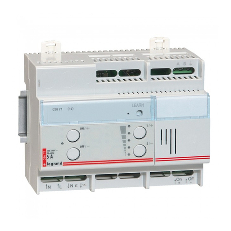
Description
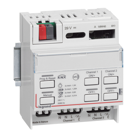
Actuator for installation in DIN rail distribution boards or
switchboards� This device incorporates two independent relays
for the activation of 2 loads, and includes local control push-
buttons for each individual load, which are only active if the
actuator has been configured� The device can be installed in a
MyHOME system and configured physically or virtually� In this
case when the PL1 and PL2 positions are configured using the
same configurator the device interlocks the relays, to which it
is possible to connect motors of rolling shutters, curtains, etc�
When installed as a component of the Lighting Management
system, specific configuration procedures are used (Plug&go,
Project&Download)�
Technical features
Power supply from BUS: 27 Vdc
Operating power supply with SCS BUS: 18 - 27 Vdc
Absorption: 28 mA
Number of outputs: 2 x 6 A
Power/Absorption of driven loads:
Legend
1� Configurator socket (attention, it must only be used in
MyHOME systems with physical configuration)
2� BUS
3� LED
4� Push-button
Incandescent lamps
Halogen lamp
LED lamp
Compact fluorescent lamp
230 Vac 1380 W 6 A 250 W Max. 4 lamps
Linear fluorescent lamp
Electronic transformer
Ferromagnetic
transformers
Motor reducers for
rolling shutters
230 W 1 A 2 A cosφ0.5 460 VA 460 W 2 A
Dissipated power with max load: 1�7 W(1)
Operating temperature: (-5) – (+45) ºC
Number of outputs: 2 x 6 A
NOTE: (1) The dissipated power indicated is that corresponding to the
device with all the relays loaded at the maximum load�
With lower loads also the dissipated power is lower and may be calculated
by means of the following formula: P(mW)=140+400*N+10*(Ic1+Ic2)
P: dissipated power in mW, N: no� of loaded relays, IN: load current
corresponding to the N relay�
Dimensional data
Size: 2 DIN modules
MyHOME Configuration
When installed in a MyHOME system, the device may be
configured in two ways:
■ PHYSICAL CONFIGURATION, by connecting the physical
configurators to their sockets�
■ VIRTUAL CONFIGURATION, by connecting the system to the
PC using the Kit or the Web server� The Virtual configurator
software must be installed on the PC�
C1 C2
ART. F411/2
1 2 43
1
2
3
4
Datasheets
2 relay actuator in DIN module
F411/2
