manuals.online logo
Brands
  1. Home
  2. •
  3. Brands
  4. •
  5. LEGRAND
  6. •
  7. Security System
  8. •
  9. LEGRAND Tynetec ZXT813 User manual

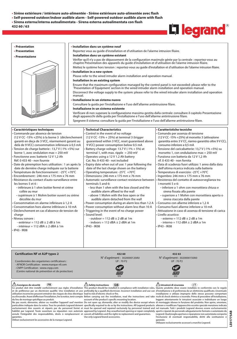
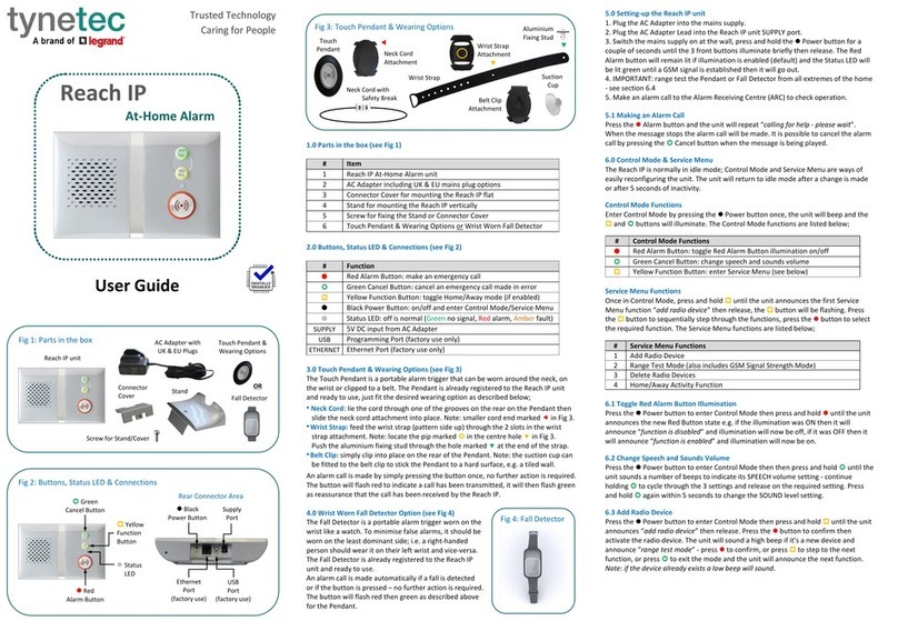
LEGRAND Tynetec ZXT813 User manual

Tynetec, a business unit of Legrand Electric Ltd
Cowley Road, Blyth Riverside Business Park, Blyth, Northumberland, NE24 5TF.
Tel: +44 (0) 1670 352371 www.tynetec.co.uk
Trusted Technology
Caring for People
869MHz
Natural Gas Alarm
869MHz
Caring for People
_________________________________________________________________________
________________________________________________________________
Doc No. FM0848 V1.00 Page 1
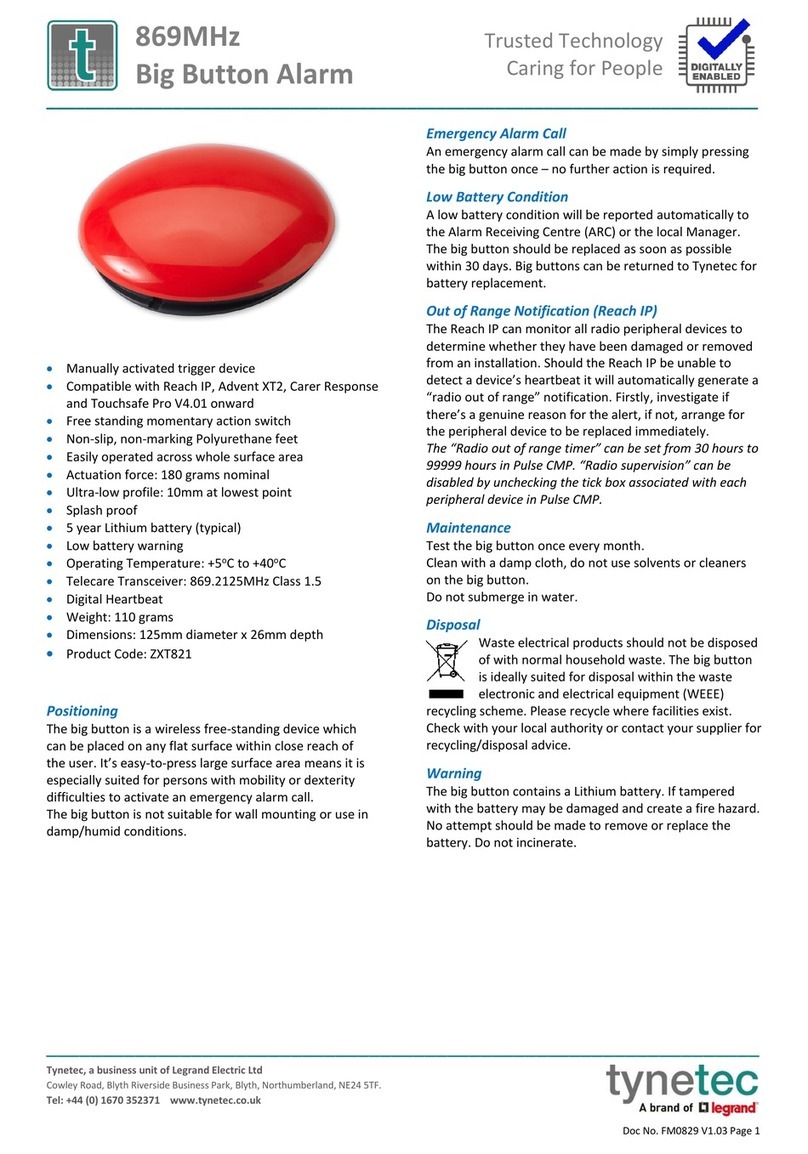
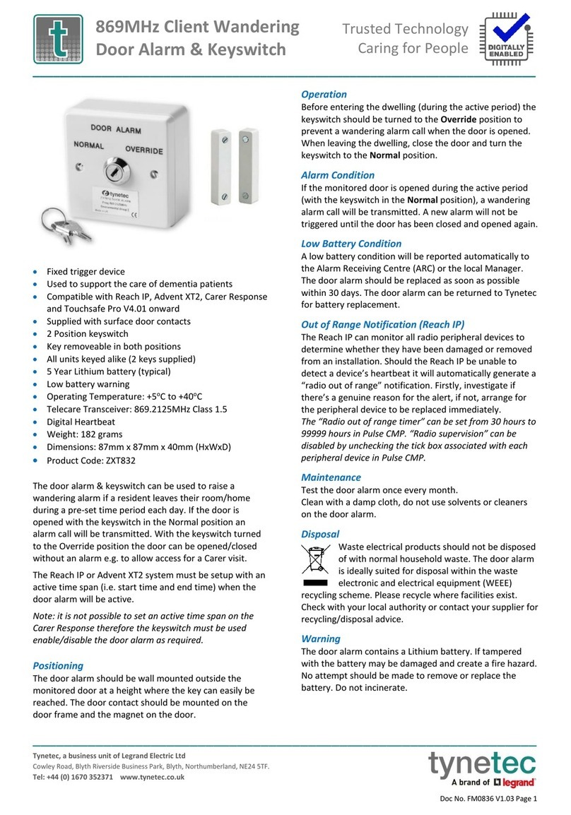
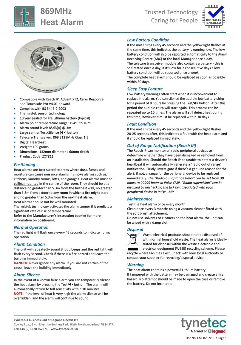
•Compatible with Reach IP, Advent XT2 & Carer Response
•Complies with EN 50194-1:2009
•Catalytic flammable gas sensor technology
•Alarm at 10% of LEL (Lower Explosive Limit) +/-2.5%
•5 year detector life
•Power Supply: 110-240V AC 50/60Hz
•Power Consumption: <6.5 Watts
•Alarm sound level: >85dB @ 1m
•Test/Hush button
•LED indicators: Green Power, Red Alarm & Yellow Fault
•Operating Temperature: -10oC to +55oC
•Telecare Transceiver: 869.2125MHz Class 1.5
•Digital Heartbeat
•5 year Lithium battery (typical)
•Low battery warning
•Weight: 585 grams
•Dimensions: 150mm x 104mm x 37mm (HxWxD)
•Product Code: ZXT813
Positioning
Gas alarms should be fitted in the room where a gas escape is
most likely to occur. For most installations the most likely source
of a gas leak will be the cooker in the kitchen.
Natural gas is lighter than air, so a leak of gas will build-up at high
level. The gas alarm should positioned above the highest window
or door opening, usually not more than 30cm from the ceiling.
The gas alarm should be located between 1 and 5 metres from
the gas appliance.
The gas alarm must not be located in or below a cupboard or in
any enclosed space, behind a curtain, directly above the cooker
or sink, next to a door or window or near an extractor fan.
Refer to the Manufacturer’s operating and installation
instructions for more information on positioning.
IMPORTANT: BS EN50244:2016 Electrical apparatus for the
detection of combustible gases in domestic premises states
that detectors should be permanently installed, and it should
not be possible to switch off power to the device, unless for
maintenance. A plug and socket type connection should not
be used, due to the ease with which the detector may be
disconnected from the power supply.
The gas alarm must be installed by a competent person
qualified to carry out electrical work according to the current
national wiring regulations.
Normal Operation
The green power light will be illuminated to indicate normal
operation.
Alarm Condition
The red alarm light will flash, and the audible alarm will sound.
Keep calm and carry-out the following actions, not necessarily in
the order given;
Extinguish all naked flames and don’t smoke
Turn off all gas appliances
Do not switch on or off any electrical equipment
Turn off the gas supply
Open doors and windows to increase ventilation
Do not use a telephone where gas may be present
When the gas clears the alarm will return to normal operation.
If the alarm continues and the cause of the leak cannot be found,
vacate the premises and contact the Gas Emergency Service on
0800 111 999 immediately.
Alarm Silence
The audible alarm can be silenced for 5 minutes by pressing the
Test/Hush button (the red light will continue to flash). If the gas is
still present after 5 minutes the alarm will sound again.
Low Battery Condition
The telecare transceiver battery is self-tested once a day, if it’s
low for 7 consecutive days a low battery condition will be
reported automatically to the Alarm Receiving Centre (ARC) or
the local Manager once a week. The complete gas alarm should
be replaced as soon as possible within 30 days.
Fault Condition
Different fault conditions are notified by the yellow fault light and
chirp patterns;
Power Fault: flashing yellow light and an intermittent single chirp
Sensor Fault: flashing yellow light and 2 long chirps per minute
Software Fault: steady yellow light and continuous chirps
For a power fault get the electrical installation checked, for other
faults the complete gas alarm should be replaced immediately.
Out of Range Notification (Reach IP)
The Reach IP can monitor all radio peripheral devices to
determine whether they have been damaged or removed from
an installation. Should the Reach IP be unable to detect a device’s
heartbeat it will automatically generate a “radio out of range”
notification. Firstly, investigate if there’s a genuine reason for the
alert, if not, arrange for the peripheral device to be replaced
immediately. The “Radio out of range timer” can be set from 30
hours to 99999 hours in Pulse CMP. “Radio supervision” can be
disabled by unchecking the tick box associated with each
peripheral device in Pulse CMP.
Maintenance
Test the gas alarm once every month.
Clean once every 3 months using a vacuum cleaner fitted with
the soft brush attachment. Do not use solvents or cleaners on the
gas alarm as they may cause damage to the sensor, the unit can
be wiped with a lightly damped cloth.
Tynetec, a business unit of Legrand Electric Ltd
Cowley Road, Blyth Riverside Business Park, Blyth, Northumberland, NE24 5TF.
Tel: +44 (0) 1670 352371 www.tynetec.co.uk
Trusted Technology
Caring for People
869MHz
Natural Gas Alarm
869MHz
Caring for People
_________________________________________________________________________
________________________________________________________________
Doc No. FM0848 V1.00 Page 2
ZXT813
S:081901023
Iss-1
16930800D3
20W37
The Radio ID is a 10-digit code
printed on the label on the
front of the gas alarm…
Disposal
Waste electrical products should not be disposed of
with normal household waste. The gas alarm is ideally
suited for disposal within the waste electronic and
electrical equipment (WEEE) recycling scheme.
Please recycle where facilities exist.
Check with your local authority or contact your supplier for
recycling/disposal advice.
How to install the Gas Alarm
Make sure you have read and understood the instructions on
positioning the alarm before starting.
Use the fixing holes on the mounting plate as a guide when
marking the position of the drill holes. Fix the mounting plate
complete with the gas alarm securely to the wall using the screws
and plugs provided.
The gas alarm should be connected to the mains supply by a
qualified Electrician. Use the flexible cable provided to a
fused spur outlet fitted with a 3A fuse to BS1363-4 and
BS1362 respectively, or according to local regulations.
Apply the mains power and check all 3 indicators light and the
unit sounds a single chirp. The 3 indicators then light in turn and
cycle 4 times. The unit is operating when the Power light is lit
steady green.
How to test the Gas Alarm
Press and hold the Test/Hush button for 1 second.
The red light will flash 4 times followed by the yellow light 4
times accompanied by the audible alarm sounding 8 times.
Note: to test the radio telecare link, press and hold the
Test/Hush button for 20 seconds then release, the green and red
lights will flash, and an alarm call will activate.
Telecare Radio ID
The gas alarm includes a radio transceiver module to
communicate with the Reach IP, Advent XT2 or Carer Response.
Registering the Gas Alarm onto a Reach IP
Login to Pulse CMP (www.tynetecpulse.com) and enter the
Reach IP Serial No. in the ALARM UNIT view.
Press the Accessories button and enter the Radio ID code,
Location and Equipment type. Press Save then Synchronize.
IMPORTANT: when the gas alarm is installed a test call must be
made to check operation and start the digital heartbeat.
Alternatively, with the Reach IP in normal operating mode undo
the fixing screw and remove the stand or connector cover to
access the ⚫Power button.
Press the ⚫Power button to enter Control Mode, then press and
hold the button until the unit announces “add radio device”
then release.
Press the ⚫button to confirm then activate the gas alarm by
pressing the Test/Hush button for 20 seconds then release.
The Reach IP unit will sound a high beep if it’s a new device and
announce “range test mode”.
Press ⚫to confirm, or press to step to the next function, or
press to exit the mode.
To check operation; press the Test/Hush button on the gas alarm
for 20 seconds then release.
Registering the Gas Alarm onto an Advent XT2
Press the Settings button on the Home page of the Manager’s
Panel. Press the Manager (or Engineer) button, enter the
password and press the Programming button.
Select the Program Radio Devices option from the tabs along the
bottom of the screen.
Press Flat ID and enter the flat number the gas alarm is being
installed in. Enter 4-digits e.g. 0014.
Press Radio ID and enter the 10-digit code taken from the label
on the front of the gas alarm.
Press Room Locations and select where the gas alarm is located
from the on-screen options e.g. Kitchen.
Press the Send button to update the XT2 system.
To check operation; press the Test/Hush button on the gas alarm
for 20 seconds then release.
⚫Power Button
Tynetec, a business unit of Legrand Electric Ltd
Cowley Road, Blyth Riverside Business Park, Blyth, Northumberland, NE24 5TF.
Tel: +44 (0) 1670 352371 www.tynetec.co.uk
Trusted Technology
Caring for People
869MHz
Natural Gas Alarm
869MHz
Caring for People
_________________________________________________________________________
________________________________________________________________
Doc No. FM0848 V1.00 Page 3
Registering the Gas Alarm onto a Carer Response
Refer to the Carer Response
user manual for full details
of the button functions
and how to navigate the
menus.
From the Main menu select
Programming.
From the Programming menu select
Add transmitter.
The display will prompt you to Activate the transmitter…
Press the Test/Hush button on the gas detector for 20 seconds
then release.
The Carer Response will beep and the display will change to the
Add transmitter menu with a box showing No ID.
Press then to select Room, then press 
Press to select the room number box 0000.
Press to select the first digit, press to move between the
digits and press or to change each digit.
Press when the correct room number is displayed.
Press to select the alarm type box None.
Press thento select Smoke Detector then press 
Press the button to select Save then press 
The display will show Radio ID saved to memory…
Return to the Main menu and select Quit
To check operation; press the Test/Hush button on the gas alarm
for 20 seconds then release.
Declaration of Conformity
We declare this product complies with the
relevant UK legislation on condition that it is used in
the manner intended, and in accordance with the
current installation standards and/or the
manufacturer's recommendations. A copy of the full UKCA
Declaration of Conformity is available on request.
We declare this product complies with the
relevant European legislation on condition that it is
used in the manner intended, and in accordance
with the current installation standards and/or the
manufacturer's recommendations. A copy of the full CE
Declaration of Conformity is available on request.
Chris Dodd
CEO
Legrand Assisted Living & Healthcare

Other LEGRAND Security System manuals

LEGRAND Tynetec ZXT817 User manual

LEGRAND

LEGRAND Tynetec ZXT817 User manual

LEGRAND Tynetec REACH User manual

LEGRAND

LEGRAND Tynetec REACH User manual

LEGRAND tynetec ZXT832 User manual

LEGRAND

LEGRAND tynetec ZXT832 User manual

LEGRAND 675 20 Quick start guide

LEGRAND

LEGRAND 675 20 Quick start guide

LEGRAND tynetec ZXT832 User manual

LEGRAND

LEGRAND tynetec ZXT832 User manual

LEGRAND tynetec ZXT821 User manual

LEGRAND

LEGRAND tynetec ZXT821 User manual

LEGRAND E47ADCN User manual

LEGRAND

LEGRAND E47ADCN User manual

LEGRAND tynetec FM0823 User manual

LEGRAND

LEGRAND tynetec FM0823 User manual

LEGRAND 4073 User manual

LEGRAND

LEGRAND 4073 User manual

LEGRAND neat SMILE FALL User manual

LEGRAND

LEGRAND neat SMILE FALL User manual

LEGRAND tynetec ZXT830 User manual

LEGRAND

LEGRAND tynetec ZXT830 User manual

LEGRAND Tynetec REACH User manual

LEGRAND

LEGRAND Tynetec REACH User manual

LEGRAND 3486 MyHome User manual

LEGRAND

LEGRAND 3486 MyHome User manual

LEGRAND 84424 User manual

LEGRAND

LEGRAND 84424 User manual

LEGRAND 43260 User manual

LEGRAND

LEGRAND 43260 User manual

LEGRAND tynetec ZXT833 User manual

LEGRAND

LEGRAND tynetec ZXT833 User manual

LEGRAND 5739 35 User manual

LEGRAND

LEGRAND 5739 35 User manual

LEGRAND tynetec ZXT823 User manual

LEGRAND

LEGRAND tynetec ZXT823 User manual

LEGRAND tynetec Aidcall ZXT434 User manual

LEGRAND

LEGRAND tynetec Aidcall ZXT434 User manual

LEGRAND tynetec Advent XT User manual

LEGRAND

LEGRAND tynetec Advent XT User manual

LEGRAND 766 21 Setup guide

LEGRAND

LEGRAND 766 21 Setup guide

LEGRAND 625 30 User manual

LEGRAND

LEGRAND 625 30 User manual

LEGRAND tynetec Reach IP User manual

LEGRAND

LEGRAND tynetec Reach IP User manual

LEGRAND Unity System User manual

LEGRAND

LEGRAND Unity System User manual

Popular Security System manuals by other brands

ADEMCO Vista 4140XMPT user manual

ADEMCO

ADEMCO Vista 4140XMPT user manual

Velleman HAM220 user manual

Velleman

Velleman HAM220 user manual

Yale SV-4C-2DB4MX quick guide

Yale

Yale SV-4C-2DB4MX quick guide

Mayon MWM903 user manual

Mayon

Mayon MWM903 user manual

TeleCare24 Fall Alarm Plan user guide

TeleCare24

TeleCare24 Fall Alarm Plan user guide

E2S D2xC2LD2 Series Instructions/service manual

E2S

E2S D2xC2LD2 Series Instructions/service manual

Amperes LS 4600 instruction manual

Amperes

Amperes LS 4600 instruction manual

Guardian LINGO Quick start user guide

Guardian

Guardian LINGO Quick start user guide

First Alert FA160C user manual

First Alert

First Alert FA160C user manual

Fenton 351.186 user manual

Fenton

Fenton 351.186 user manual

Glentronics PRO Series instruction manual

Glentronics

Glentronics PRO Series instruction manual

AQUABAND AHQ-10 operating manual

AQUABAND

AQUABAND AHQ-10 operating manual

Metra Electronics Spyclops PRO MTH1301 quick start guide

Metra Electronics

Metra Electronics Spyclops PRO MTH1301 quick start guide

Samsung SDH-P4041 user manual

Samsung

Samsung SDH-P4041 user manual

MEDC LD15 UL Technical manual

MEDC

MEDC LD15 UL Technical manual

Lorex SG14Q2144C-A instruction manual

Lorex

Lorex SG14Q2144C-A instruction manual

On Automation FL1 instruction manual

On Automation

On Automation FL1 instruction manual

MOFLASH SIGNALLING R201 Series Installation and technical information

MOFLASH SIGNALLING

MOFLASH SIGNALLING R201 Series Installation and technical information

manuals.online logo
manuals.online logoBrands
  • About & Mission
  • Contact us
  • Privacy Policy
  • Terms and Conditions

Copyright 2025 Manuals.Online. All Rights Reserved.