manuals.online logo
Brands
  1. Home
  2. •
  3. Brands
  4. •
  5. LEGRAND
  6. •
  7. Security System
  8. •
  9. LEGRAND Tynetec REACH User manual

LEGRAND Tynetec REACH User manual

TRUSTED TECHNOLOGY.
CARING FOR PEOPLE
FUTURE PROOF IP READY TECHNOLOGY
REACH/REACH
PLUS ALARM UNIT
Please find enclosed your At-Home Alarm and Touch 2 Pendant.
All the equipment is ready to use (see below) and will be activated by following the
instructions overleaf.
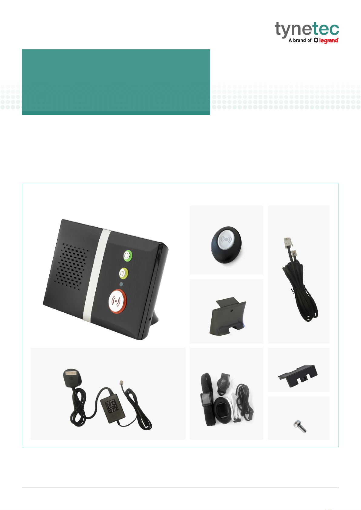
Supplied in the box...
Self Installation
instructions
At-Home Alarm
Connector CoverWearing Kit
Screw for
Stand/Cover
Touch 2 Pendant
AC Adapter with UK and EU Plugs
Registered Office: Great King Street North, Birmingham, B19 2LF. Registered in England No. 00115834
Legrand Assisted Living & Healthcare
Blyth Workspace, Commissioners Quay, Quay Road, Blyth, Northumberland NE24 3AG.
T: +44 (0) 1670 352 371 | www.aidcall.co.uk | www.jontek.co.uk | www.tynetec.co.uk
Telecom Lead
- 3 -
1. IMPORTANT INFORMATION
The users telephone MUST BE connected to the Alarm Unit
¢¢
TEL socket – a double adapter on the
incoming line must not be used.
If the user has extension telephones care should be taken to ensure that these are also connected via the
Alarm Unit
¢¢
TEL socket.
Failure to connect the users telephones as described above may cause difficulties with alarm calls – if in
doubt seek advice.
If the user has a DECT telephone the base station MUST BE at least 2 metres away from the Alarm Unit.
Failure to provide this separation may result in reduced range of personal pendants or other radio devices.
REN 1
All telephone equipment has a Ringer Equivalence Number (REN) which is used to calculate the number of
items that can be connected to a single telephone line.
A REN of 4 is the maximum allowed on a standard UK telephone line - the Alarm Unit has a REN of 1
If the REN total of all equipment connected to a telephone line exceeds 4 the equipment may not operate
correctly. With different types of equipment there is no guarantee of correct operation even if the REN is
less than 4. Typically 1 or 2 standard telephones (REN 1) can be used with the Alarm Unit.
Avoid using strong detergents or polish when cleaning the Alarm Unit unit or Touch pendant.
Wipe clean with a damp cloth and polish with a dry duster.
2. UNPACKING THE AT-HOME ALARM
The At-Home Alarm is supplied with a Power Lead, a Telecom Lead, a Touch Pendant and a wearing kit.
A stand can be fitted if the unit is being mounted upright or a connector cover if it is being placed flat.
The stand/cover must be fixed with the screw provided.
Touch Pendant
Wearing Kit
At-Home Alarm
Connector Cover
Telecom Lead
Stand
Stand/Cover Screw
Power Lead
Stand
TRUSTED TECHNOLOGY.
CARING FOR PEOPLE
FUTURE PROOF IP READY TECHNOLOGY
Setting-up the Reach/
Reach Plus At-Home
Alarm unit
Registered Office: Great King Street North, Birmingham, B19 2LF. Registered in England No. 00115834
Legrand Assisted Living & Healthcare
Blyth Workspace, Commissioners Quay, Quay Road, Blyth, Northumberland NE24 3AG.
T: +44 (0) 1670 352 371 | www.aidcall.co.uk | www.jontek.co.uk | www.tynetec.co.uk
Unplug the Telephone from the BT wall socket and plug it into the Alarm unit TEL socket.
1
Simply press the Touch
2 Pendant button once.
The button will FLASH
RED (( )) for several
seconds to confirm a
call is being made.
Test your Touch 2 Pendant from the furthest
points in your home.
The Alarm unit will announce “Please wait
- dialing for assistance” and you will be
connected to your provider who will confirm
you are all operational.
4
Making an Alarm Call from the Reach/Reach Plus unit
Press the large red button on the front of the unit and it will announce
“Please wait - dialing for assistance” and the alarm call will be made.
Telephone BT wall
socket
At-Home
Alarm unit
Mains
electricity supply
Power lead
Telecom
lead
C/O TEL SUPPLY
Reverse of
Alarm unit
Connect the Telecom lead between the
Alarm unit C/O socket and the BT wall
socket where the telephone was originally
plugged in. If you have broadband your
service provider will supply an ADSL Filter
module to plug into the telephone line.
To connect the computer, telephone and
Reach unit see diagram (right):
2At-Home
Alarm unit
Telephone BT wall
socket
ADSL
Filter
Place the Alarm unit close to the BT wall
socket and an available Mains electricity
supply (ideally without using an extension).
Plug in the Power lead between the Alarm
unit SUPPLY socket and the mains supply.
Switch on and the front light will flash RED/
AMBER/GREEN for about 12 seconds.
3
The status light will
turn green once the
unit has a signal.
This may take up to
1 minute.

Other manuals for Tynetec REACH

1

This manual suits for next models

1

Other LEGRAND Security System manuals

LEGRAND Tynetec ZXT813 User manual

LEGRAND

LEGRAND Tynetec ZXT813 User manual

LEGRAND E47ADCN User manual

LEGRAND

LEGRAND E47ADCN User manual

LEGRAND tynetec ZXT832 User manual

LEGRAND

LEGRAND tynetec ZXT832 User manual

LEGRAND neat SMILE FALL User manual

LEGRAND

LEGRAND neat SMILE FALL User manual

LEGRAND tynetec ZXT821 User manual

LEGRAND

LEGRAND tynetec ZXT821 User manual

LEGRAND tynetec ZXT830 User manual

LEGRAND

LEGRAND tynetec ZXT830 User manual

LEGRAND 5739 34 User manual

LEGRAND

LEGRAND 5739 34 User manual

LEGRAND Tynetec REACH User manual

LEGRAND

LEGRAND Tynetec REACH User manual

LEGRAND 5739 35 User manual

LEGRAND

LEGRAND 5739 35 User manual

LEGRAND 766 21 Setup guide

LEGRAND

LEGRAND 766 21 Setup guide

LEGRAND 625 30 User manual

LEGRAND

LEGRAND 625 30 User manual

LEGRAND 675 20 Quick start guide

LEGRAND

LEGRAND 675 20 Quick start guide

LEGRAND 4073 User manual

LEGRAND

LEGRAND 4073 User manual

LEGRAND L4601 User manual

LEGRAND

LEGRAND L4601 User manual

LEGRAND tynetec ZXT832 User manual

LEGRAND

LEGRAND tynetec ZXT832 User manual

LEGRAND tynetec Advent XT User manual

LEGRAND

LEGRAND tynetec Advent XT User manual

LEGRAND 84424 User manual

LEGRAND

LEGRAND 84424 User manual

LEGRAND 3486 MyHome User manual

LEGRAND

LEGRAND 3486 MyHome User manual

LEGRAND tynetec ZXT823 User manual

LEGRAND

LEGRAND tynetec ZXT823 User manual

LEGRAND 43260 User manual

LEGRAND

LEGRAND 43260 User manual

LEGRAND tynetec FM0823 User manual

LEGRAND

LEGRAND tynetec FM0823 User manual

LEGRAND Unity System User manual

LEGRAND

LEGRAND Unity System User manual

LEGRAND tynetec ZXT833 User manual

LEGRAND

LEGRAND tynetec ZXT833 User manual

LEGRAND tynetec Aidcall ZXT434 User manual

LEGRAND

LEGRAND tynetec Aidcall ZXT434 User manual

Popular Security System manuals by other brands

DSC Neo Power Series installation guide

DSC

DSC Neo Power Series installation guide

Kompernass TA 120 A2 operating instructions

Kompernass

Kompernass TA 120 A2 operating instructions

Response Electronics miGuard G5 Installation and operating instructions

Response Electronics

Response Electronics miGuard G5 Installation and operating instructions

EnOcean EOSW installation guide

EnOcean

EnOcean EOSW installation guide

Bewator Bewacard BC615 quick guide

Bewator

Bewator Bewacard BC615 quick guide

Brain Sentinel Seizurelink user manual

Brain Sentinel

Brain Sentinel Seizurelink user manual

Bosch DIP-3042-2HD installation manual

Bosch

Bosch DIP-3042-2HD installation manual

Arrowhead KP600L Features and specifications

Arrowhead

Arrowhead KP600L Features and specifications

DMP Electronics XR500 SERIES user guide

DMP Electronics

DMP Electronics XR500 SERIES user guide

Elkron MP 200 user manual

Elkron

Elkron MP 200 user manual

TWIG One Ex quick guide

TWIG

TWIG One Ex quick guide

M-system KSE-1 instruction manual

M-system

M-system KSE-1 instruction manual

HumanTechnik Lisa A-2414-0 operating instructions

HumanTechnik

HumanTechnik Lisa A-2414-0 operating instructions

Cocoon DY180381 quick start guide

Cocoon

Cocoon DY180381 quick start guide

Digital Systems DS512 user manual

Digital Systems

Digital Systems DS512 user manual

Neptune NE7MHDWCB user manual

Neptune

Neptune NE7MHDWCB user manual

Sharp CD-M10000V Operation manual

Sharp

Sharp CD-M10000V Operation manual

EVERSPRING HSE03 installation instructions

EVERSPRING

EVERSPRING HSE03 installation instructions

manuals.online logo
manuals.online logoBrands
  • About & Mission
  • Contact us
  • Privacy Policy
  • Terms and Conditions

Copyright 2025 Manuals.Online. All Rights Reserved.