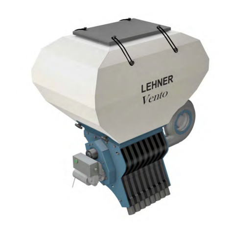
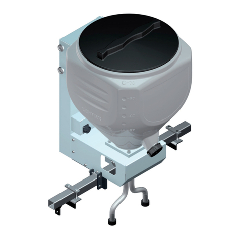
LEHNER Vento User manual

Operating manual with parts list
Vento®
Controller: LAS PSM
Software: from Version 8.08 onwards
Last updated: February 2015
Serial number: ..................................................
Software version: ..................................................
Translation of original operating manual

Publisher's information
2 / 52 1.0 Vento®
Publisher's information
LEHNER Agrar GmbH
Häuslesäcker 5-9
D-89198 Westerstetten
Tel.: (+49) 7348 95 960
Fax: (+49) 7348 959 640
www.lehner.eu
This document is not allowed to be distributed, duplicated or utilised, nor is its content allowed to be communicated,
without express permission. Contraventions shall require compensation in damages. All rights reserved in the event
of patent, utility model or design registration.
English

Table of contents
Vento®1.0 3 / 52
Table of contents
1 What you should know........................................................................... 5
1.1 Foreword.............................................................................................. 5
1.2 About this operating manual................................................................5
1.3 About your safety.................................................................................5
1.4 Notices used........................................................................................ 5
1.5 Intended use........................................................................................ 6
1.6 Reasonably predictable misuse...........................................................6
1.7 Scope of supply................................................................................... 6
1.8 Warranty...............................................................................................7
1.9 Technical data of Vento®.................................................................... 7
1.10 Description of function......................................................................... 7
2 Mounting and start-up............................................................................ 8
2.1 Implement holder................................................................................. 8
2.2 Installing hoses.................................................................................... 8
2.3 Electrical connection............................................................................ 9
2.4 Filling the Vento®.............................................................................. 10
3 Operation................................................................................................ 12
3.1 Controls on the control panel............................................................ 12
3.2 Switching on/off..................................................................................12
3.3 Information shown on the display......................................................12
3.4 General setting possibilities and displays..........................................13
3.5 Automatic dosing............................................................................... 18
3.6 Setting the blower..............................................................................19
3.7 Changing the settings........................................................................20
3.8 Manual mode..................................................................................... 20
3.9 Residual discharge............................................................................ 21
3.10 Error message................................................................................... 22
3.11 Troubleshooting..................................................................................22
4 Maintenance and cleaning....................................................................24
4.1 Maintenance schedule....................................................................... 24

Table of contents
4 / 52 1.0 Vento®
4.2 Spreading material hopper................................................................ 25
4.3 Rotary feeder shaft............................................................................ 26
4.4 Drive belt............................................................................................27
4.5 Brushes.............................................................................................. 28
4.6 Blower................................................................................................ 29
5 Storage and disposal............................................................................ 30
6 Appendix.................................................................................................31
6.1 Identification....................................................................................... 31
6.2 Dimensions.........................................................................................31
6.3 Overview of rotary feeder shafts....................................................... 33
6.4 Formulas............................................................................................ 33
6.5 Spreading material lists..................................................................... 34
6.6 Spare parts and accessories.............................................................39

What you should know
Vento®1.0 5 / 52
1 What you should know
1.1 Foreword
With the Vento® you have acquired a high-quality and innovative product. Thank you for this expression of confi-
dence.
Thanks to its advanced design, meticulous material selection, state-of-the art manufacturing techniques and the
precision work of our employees, this equipment meets all efficiency, quality, reliability and value requirements.
Maintenance and cleaning as detailed in the operating manual ensure the safety and retain the value of your Ven-
to®.
1.2 About this operating manual
This operating manual is an important component of the spreader and must always be kept close to hand. All per-
sons who work with the spreader must read, understand and follow the operating manual.
Keep the operating manual in a safe place. If you sell your spreader, always provide this operating manual to the
buyer.
1.3 About your safety
Read through this operating manual carefully before starting operation. Comply with the instructions, warnings and
safety information. Always keep this manual to hand at the point of use.
•Observe the accident prevention regulations, safety and operating regulations and the regulations for environ-
mental protection.
•Observe all applicable standards and guidelines.
•Observe the safety instructions.
•Wear appropriate working and protective clothing.
•Avoiding injury to personnel or damage to vehicles incurring liability.
•Before operation, check that the spreader is safely and correctly attached to the carrier vehicle.
•Do not take the spreader into operation if there are technical safety defects.
•Make sure that technical safety defects are rectified immediately.
•When travelling on public roads and tracks used by agricultural vehicles, follow the applicable rules of the road.
•No other persons or animals are allowed to be in the spreading zone.
•Never open the hopper during operation.
•Disconnect the mains plug before maintenance, troubleshooting, repair and cleaning work on the spreader.
•Comply with the safety instructions on the fertiliser that you are using.
•It is essential to comply with the instructions of the pesticide or fertiliser manufacturer in question.
•After completing work, always perform a complete residual discharge of the spreader.
•Spreading tables and additional information about the fertiliser used can be requested from the manufacturer in
question.
•LEHNER Agrar GmbH does not accept any liability for storage and use of spreading material (seeds and fertilis-
er).
1.4 Notices used
Warning notices
Warning notices in this operating manual are identified as follows:

What you should know
6 / 52 1.0 Vento®
Danger!
Warning against immediate danger.
Non-observance of appropriate measures will result in death or severe personal injury.
Warning!
Warning against possible danger.
Death or severe personal injury is possible.
Caution!
Warning of possible dangerous situations.
Slight personal injury or damage to property is possible.
Notices
Notices in this operating manual are identified as follows:
Advice!
For application instructions and other useful information.
1.5 Intended use
The Vento® is exclusively used for spreading seeds and fertiliser in granulated form.
The seeds and fertiliser used must be free-flowing and, due to technical reasons, permit application by dosing. In
case anything is unclear, please contact the product specialists at Lehner.
The pneumatic granulate doser is only allowed to be used within the scope of its designated use.
1.6 Reasonably predictable misuse
Vento® is only allowed to be used for permitted seeds and fertiliser.
Vento® is only allowed to be used on approved carrier vehicles with an adequate axle load and a vehicle electrical
system with 12-15 volts and 25 amp current capacity at least.
1.7 Scope of supply
The Vento® consists of the following components:
•Pneumatic granulate doser with blower and spreading material hopper, pre-mounted on a universal holder
•Control panel with battery cable
•25 m hose
•8 baffle plates (complete and ready to install)
•8 hose grommets
Optional accessories
•Wheel sensor
•GPS sensor

What you should know
Vento®1.0 7 / 52
•Headland Manager (VGM) sensor magnet
•Y-cable for speed signal via 7-pin socket as well as VGM sensor/magnet
•Y-cable AccoSat for speed signal via GPS receiver as well as VGM sensor/magnet
At the time of manufacture, we are not aware of any negative effects from the seed and fertiliser on the materials of
the spreader.
1.8 Warranty
Subject to use in accordance with the designated use, LEHNER Agrar GmbH offers a 24-month warranty on the
spreader.
Caution!
Danger of short circuit!
Faulty or incorrectly sized plugs and cables can lead to malfunctions. Only use original plugs
and cables, or ones approved by the manufacturer.
Warranty repairs must be coordinated with LEHNER Agrar GmbH before any work is started.
For replacement parts, additional expenses are charged for any changes made to cables and plugs by the cus-
tomer.
Replacement parts are to be returned carriage paid.
Any changes to cable or plug connections without factory approval automatically invalidate the entire warranty.
Rusted bearings are not subject to the manufacturer's warranty.
Motors are not allowed to be opened or dismantled.
On receipt:
Please check the goods on receipt to ensure they are undamaged and nothing is missing.
If there has been damaged in transit, please inform the manufacturer within 24 hours!
1.9 Technical data of Vento®
Vento®
120 litre hopper
Vento®
230 litre hopper
Length [mm] 527 570
Width [mm] 919 947
Height [mm] 1009 1199
Weight, empty [kg] 60.5 67
Spreading with [m] ≤ 6 ≤ 6
1.10 Description of function
The Vento® is a pneumatic granulate doser for applying seeds and granulated fertiliser in agriculture.
Precise dosing is achieved using a rotary feeder valve that is driven according to the speed of the vehicle. Auto-
matic dosing by means of a wheel sensor or GPS receiver is possible. The spreader has an agitator for spreading
materials with reduced free-flowing properties. The spreading material is applied by means of an airflow through 8
hoses.

Mounting and start-up
8 / 52 1.0 Vento®
2 Mounting and start-up
Warning!
Risk of injury due to inadequate attachment
If the spreader or hopper tip over, this can cause crushing or other injuries.
•Only mount the spreader on carrier vehicles that have a sufficient load carrying capability.
•Before start-up, make sure that the implement, spreading material hopper and hopper cover have
been correctly attached.
2.1 Implement holder
The Vento® is supplied mounted on the universal holder
as standard. The mounting is specifically dependent up-
on the carrier vehicle provided, and must be adapted to
its conditions.
Before operation, check the attachment of the spread-
er on the universal holder. The attachment must be se-
cured with the safety bolts (1). If replacing them, use
M10 bolts with a strength class of at least 8.8, with self-
locking nuts.
Optionally, mounting is possible using U-brackets (2) on
a square tube with dimensions 80×80 mm to 120×120
mm.
2.2 Installing hoses
Advice!
Route hoses with as few bends as possible, and with the largest possible bending radius.
Incorrect hose routing can result in blockages in the hose.
Only insert clean hose grommets into the holder.
Installing hose
1. Screw hose grommet (2) onto hose.
2. Push hose grommet (2) into the holder (1) until it en-
gages.
3. Route the hose and cut to length.
4. Cut the hose off with a straight end.
5. Attach baffle plate (3) to the hose with a hose clip.

Mounting and start-up
Vento®1.0 9 / 52
2.3 Electrical connection
Caution!
Risk of short-circuit and injury when working on the battery and electrical system!
Electrical current flowing through the body can cause cramps, ventricular fibrillation,
heart stoppage and internal burns. Risk of burns due to arcing caused by short circuits.
•Protect the battery against damage and moisture.
•Disconnect the electrical power supply before starting work on the battery and electrical system.
•Use suitable tools so as to avoid short circuits.
•Sure that the cables are routed without tension, kinking and chafing, and also avoid bending them
around sharp edges.
•During all work on the battery, please comply with the regulations of the vehicle manufacturer in
question.
•Only use original cables, or ones approved by the manufacturer.
•Always push on the cap and lock it to protect electrical connections against damage.
Advice!
Faulty cables or cables with incorrect dimensions can lead to malfunctions and damage to the spread-
er. Any changes to cable or plug connections without factory approval automatically invalidates the entire
warranty.
Changes to cables undertaken by the customer are taken into account in the case of repair. Only use original ca-
bles, or ones approved by the manufacturer. You must consult with the manufacture before carrying out any cable
modifications. Power loss must be taken into account when extending cables. A poor power supply may prevent you
from achieving the desired blower speed. Also, this could lead to intermittent complete failure.
2.3.1 Technical data, electrical system
Operating voltage 12 to 15 V
Fuse 25 A
Speed range 20 to 120 rpm
Power consumption of motor 8.5 A
Operating temperature 10 to +50 °C
Storage temperature -10 to +50 °C
Battery cable minimum 6 mm²
2.3.2 Mounting the control panel
1. Mount support for the control panel in the vehicle cabin.
2. Plug the control panel cable into the 3-pin socket (1) of the supplied battery cable.
Connect connection (2) to the negative terminal of the battery (not to the bodywork).

Mounting and start-up
10 / 52 1.0 Vento®
Connect connection (3) with fuse (4) to the positive terminal of the battery. Run the end of the cable with the
socket to the carrier vehicle.
3. Plug the control cable of the spreader into the multi-pin socket of the control panel.
Advice!
To ensure an optimum electrical power supply, use the supplied battery cable.
The spreader is ready for use.
2.4 Filling the Vento®
Warning!
Risk of injury during operation if the spreading material hopper is open, due to spread-
ing material being thrown out and rotating parts.
This can cause injuries to the eyes and crushing injuries.
•Only operate when the hopper cover is closed.
•Always switch off the spreader and blower before opening the spreading material hopper.
Warning!
Risk of injury!
•Wear appropriate working and protective clothing during all work.
•Comply with the regulations of the fertiliser manufacturer.
Advice!
Attach the data sheet of the fertiliser used in a clearly visible position on the spreader.
Advice!
Make sure that no foreign bodies (e.g. packaging material) get into the hopper, in order to avoid malfunc-
tions.

Mounting and start-up
Vento®1.0 11 / 52
Before start-up, make sure that the hopper on the Vento® has been firmly bolted in place. To do this, check the four
knurled screws (1).
Filling
1. Make sure that the spreader and blower are
switched off.
2. To fill the spreader, release the rubber clamping
band (2) on the hopper and remove the cover (3).
3. Make sure that suitable rotary valves are fitted ac-
cording to the spreading material table, and that the
load relief roof of the agitator has been mounted cor-
rectly.
4. Fill the spreading material, making sure that no for-
eign bodies or impurities get into the hopper.
5. Before closing the hopper, make sure that the
seal is in place all round between the hopper
and the hopper cover.
6. Close the hopper with the four rubber clamping
bands (2) making a firm seal.
Warning!
Incorrect filling will lead to incorrect dosing applications.
•The hopper cover must be closed during operation, in order to avoid incorrect dosing applications.

Operation
12 / 52 1.0 Vento®
3 Operation
3.1 Controls on the control panel
Controls
1On/Off key
2Display
3Start/stop spreader
Green LED lights up: Rotary feeder valve drive mo-
tor running
Green LED flashes: waiting for electronic lifting
gear control (EHR) enable signal and/or speed
Yellow LED lights up: Rotary feeder valve drive mo-
tor off
4Toggle switch for menu control by the program
5+ and - keys for altering the rotation speed of the
rotary feeder valve as well as navigating through
various menu functions
10 Switch automatic dosing on and off
11 Blower speed
Connections
6Socket for wheel sensor
7Control cable from spreader
8Battery cable 6 mm²
9Socket for EHR magnet sensor or 7-pin connection,
GPS, Y-cable
3.2 Switching on/off
When the control panel is switched on, the versions of the hardware and software are
displayed briefly.
Press the key.
LED above the key lights up: Spreader is ready for operation and in auto-
matic dosing operating mode.
The blower starts when set to at least 20% of the blower power.
.
c
3.3 Information shown on the display
c
.
Automatic dosing
1. Selected spreading table
2. Working width
3. Output rate in kg/ha

Operation
Vento®1.0 13 / 52
Changeover using AUTO key
M l FV
OFF
Manual mode
1. Manual operating mode
2. Current speed of the rotary feeder valve
3. Dosing OFF: Rotary feeder valve drive motor off
Dosing ON: Rotary feeder valve drive motor running
3.4 General setting possibilities and displays
The control element can be used to make the following settings:
•Language
•Displaying product lists and deleting products
•Qty. adaptation
•Calibrating the wheel sensor
•Setting the EHR signal
•Entering the calibration values
•Creating products
3.4.1 Language
Switch off the spreader.
Press the +key, the - key and the On/Off key simultaneously.
Keep all three keys pressed for about 3 seconds.
L ng g
Engli
Press the key to set the language.
L ng g
Engli
Use the On/Off key to exit the menu.
3.4.2 Displaying product lists and deleting products
Switch off the spreader.
key, the +key, the - key and the On/Off key simultaneously.
Keep all three keys pressed for about 3 seconds.
L ng g
Engli

Operation
14 / 52 1.0 Vento®
Press the toggle switch to call up the product list.
V w
o
Press the + key to scroll in the list.
C
g s
Press the toggle switch again to be able to delete products.
D
o
Press the + key to scroll in the list.
D
o
Press the - key to delete the displayed product. Product 1 can-
not be deleted!
D
o
Use the On/Off key to exit the menu.
3.4.3 Changing the settings
The output rate, working width and product can be set directly. A product change is only possible if several products
have already been stored. "Product 1" is a factory setting. Creating new products, see Chapter 3.4.8, "Spreading ta-
bles and calibration procedure".
Press toggle switch. The selected value flashes and can be set. To move to
the next item, or to return to operating mode, press the toggle switch again.
c
.
Press the +/- keys to switch between the stored products or to change the
numerical values.
3.4.4 Quantity adaptation (only in AUTO mode)
Please note that at this item is only available in the automatic area.
The spreading value stored in the spreading table can be changed temporarily. This change is not stored when the
spreader is switched off.

Operation
Vento®1.0 15 / 52
Press the Automatic dosing key for approx. 6 seconds.
Qty. d t tio
Press the + + key to increase the spreading value up to 50 %.
Press the - key to reduce the spreading value up to 50 %.
Press the Automatic dosing key to return to the operating mode.
3.4.5 Electronic lifting gear control (EHR) function
The spreader is stopped automatically when the front or rear hydraulics of the carrier vehicle are lifted. The spread-
er can be stopped manually at any time using the control panel.
The signal can be detected by means of a 7-pin plug or a sensor signal.
7-pin socket
1. Connect the connecting cable of the control panel to
the 7-pin signal socket of the carrier vehicle.
2. Set the EHR signal of the carrier vehicle depending
on whether the carrier vehicle sends the hydraulic
signal when lifting or lowering.
Sensor signal
Advice!
Please note that the contact surfaces (1) of the sensor are only located on the left and
right sides.

Operation
16 / 52 1.0 Vento®
1. Mount the sensor in the joint section of the lower link.
2. Mount the magnetic encoder to the lower link.
3. Set the position of the sensor and the magnetic encoder. Maximum distance 8 mm.
Hydraulics lowered:
Sensor is not allowed to be in field of magnetic encoder. Dosing stops (see EHR setting: high active or low active).
Hydraulics lifted:
Sensor must still be in field of magnetic encoder. When the hydraulics are lifted, the sensor must not leave the field
of the magnetic encoder, as otherwise the dosing will start again.
3.4.6 Setting setting signal for electronic lifting gear control (EHR)
The spreader is equipped ex-works with EHR signal communication (socket). The hydraulic signal is taken from the
7-pin EHR socket of the carrier vehicle or from the sensors attached to the lower link (install magnet with sensor on
lower link - option).
Depending on the carrier vehicle, the signal is output on lifting or on lowering. Check the EHR signal is set correctly
and correct it if necessary.
Press the Automatic dosing key for approx. 6 seconds.
Qty. d t tio
Press the toggle switch twice.
C l. w l .
Y S
Press the key to set the EHR signal.
EHR signal for lifting: High active is displayed
EHR signal for lowering: Low active is displayed
s
c e
Press the Automatic dosing key to return to the operating
mode.
Press the Automatic dosing key for approx. 6 seconds.
Press the toggle switch three times.
Press the toggle switch to display the setting for the speed sen-
sor of the EHR signal. Adapt the speed signal with the +/- keys.
Factory setting: 130 /m

Operation
Vento®1.0 17 / 52
Press the Automatic dosing key to return to the operating
mode.
3.4.7 Calibrating the wheel sensor
To calibrate the wheel sensor, it is necessary to move a distance of exactly 100 m.
Press the Automatic dosing key for approx. 6 seconds.
Qty. d t tio
Press the toggle switch once. Press the + key to confirm.
C l. w l .
Y S
Press the + key, the calibration procedure starts.
After moving 100 m, press the - key, the calibration procedure is finished.
C l un
Press the + key to store the value.
to .
Y
O
Press the Automatic dosing key to return to the operating mode or
wh
.
If both an EHR signal and a wheel sensor signal are being output, the wheel sensor signal always takes priority.
3.4.8 Spreading tables and calibration procedure
Calibration procedure
1. Pull off all hoses on the spreader.
2. Place a collecting container under the outlets.
3. Start the calibration procedure:
Briefly press the toggle switch twice within one second.
Then press the toggle switch again.
C li s
YE
Press the + key.
The spreader starts the calibration procedure. The calibration procedure
has finished as soon as the spreader stops, and a weight value is shown
on the display.
Cali ati g
4. Weigh the spreading material dispensed and input this weight:

Operation
18 / 52 1.0 Vento®
Press the +/- keys to enter the weighed value and confirm with
the toggle switch.
I p
Press the + key to store the value.
Y
O
av
5. Select the product name/spreading table or create a new one:
Press the + key in order to save the entered value in the
"Product 1" spreading table.
Press the - key in order to save the entered value with a new
product name.
Y S
O
c
Press the +/- keys to select the letters or numbers and confirm
each one with the toggle switch.
w n
Press the toggle switch twice to save the name in the spreading
table.
The program automatically returns to the operating mode.
3.5 Automatic dosing
With automatic dispensing, the speed of the rotary feeder is calculated according to the following values:
•Speed
•Output rate
•Working width
•Calibration value of the spreading material
The calibration value can be stored in a spreading table, see Chapter 3.4.8, "Spreading tables and calibration pro-
cedure".
The output rate, working width and product can be set directly, see Chapter 3.4.3, "Changing the settings".
Display with automatic dosing:
The following appears on the display:
•Product name (spreading table used)
•Distance between plant or seed rows
•Output rate
.
c

Operation
Vento®1.0 19 / 52
Starting automatic dosing:
Warning!
Risk of injury!
Make sure that no other persons or animals are in the danger zone during operation.
Automatic dosing can only be started a speed signal is received and a lifting gear signal is output, see Chapter 3.10,
"Error message".
Press the key.
Dosing starts when the speed is faster than 2 km/h and the hydraulics are
lowered.
c
FV
Green LED lights up. Rotary feeder drive motor running.
The following is shown in the display:
•Product name (spreading table used)
•Speed of the rotary feeder
•Travel speed
An audible signal indicates when dosing has started correctly. Three audible signals indicate there is a fault and
dosing has not been started.
The green LED flashes if the speed or lifting gear signal is not received.
Stopping automatic dosing:
The spreading procedure can be stopped at any time by pressing the key.
Otherwise, dosing is stopped automatically when the hydraulics are raised or the travel speed is less than 1.5 km/h.
The spreading procedure restarts when both signals are received again.
After an automatic interruption, it is necessary to press the key again in order to restart the dosing.
3.6 Setting the blower
Using the dial, it is possible to set the blower power according to the product type and output rate,
until achieving satisfactory material transport.
Advice!
Setting a high blower power increases energy consumption.
Lateral distribution can be varied by means of the blower power.

Operation
20 / 52 1.0 Vento®
3.7 Changing the settings
The output rate, working width and product can be set directly. A product change is only possible if several products
have already been stored. "Product 1" is a factory setting. Creating new products, see Chapter 3.4.8, "Spreading ta-
bles and calibration procedure".
Press toggle switch. The selected value flashes and can be set. To move to
the next item, or to return to operating mode, press the toggle switch again.
c
.
Press the +/- keys to switch between the stored products or to change the
numerical values.
3.8 Manual mode
In manual mode, the speed of the rotary feeder is set manually.
Setting
Press the Automatic dosing key.
This changes over between automatic dosing and manual mode.
Display in manual mode
The following appears on the display:
•Manual: Manual operating mode
•Speed of the rotary feeder in rpm
•Dosing OFF: Rotary feeder valve drive motor off
Start dosing
Manual operation is possible with or without electronic lifting gear control (EHR).
Manual operation without EHR
Setting the speed
Press the +/- keys to change the speed.
Warning!
Risk of injury!
Make sure that no other persons or animals are in the danger zone during operation.
Table of contents
Other LEHNER Spreader manuals

LEHNER
LEHNER SuperVario Guide

LEHNER
LEHNER SuperVario X Guide

LEHNER
LEHNER POLARO Datasheet

LEHNER
LEHNER Polaro L Datasheet

LEHNER
LEHNER SuperVario User manual

LEHNER
LEHNER POLARO User manual

LEHNER
LEHNER POLARO User manual

LEHNER
LEHNER Vento II Guide

LEHNER
LEHNER MiniVario E Datasheet

LEHNER
LEHNER POLARO E Datasheet
Popular Spreader manuals by other brands

Roda
Roda R2000 Truck manual

Echo
Echo RB-85W Operator's manual

Maruyama
Maruyama FLEX-SELECT F80P Series Assembly and operating instructions

Trynex
Trynex SnowEx SP-8550 Owner's/operator's manual

Harbor Freight Tools
Harbor Freight Tools 99621 Set up and operating instructions

The Handy
The Handy THS50 instruction manual