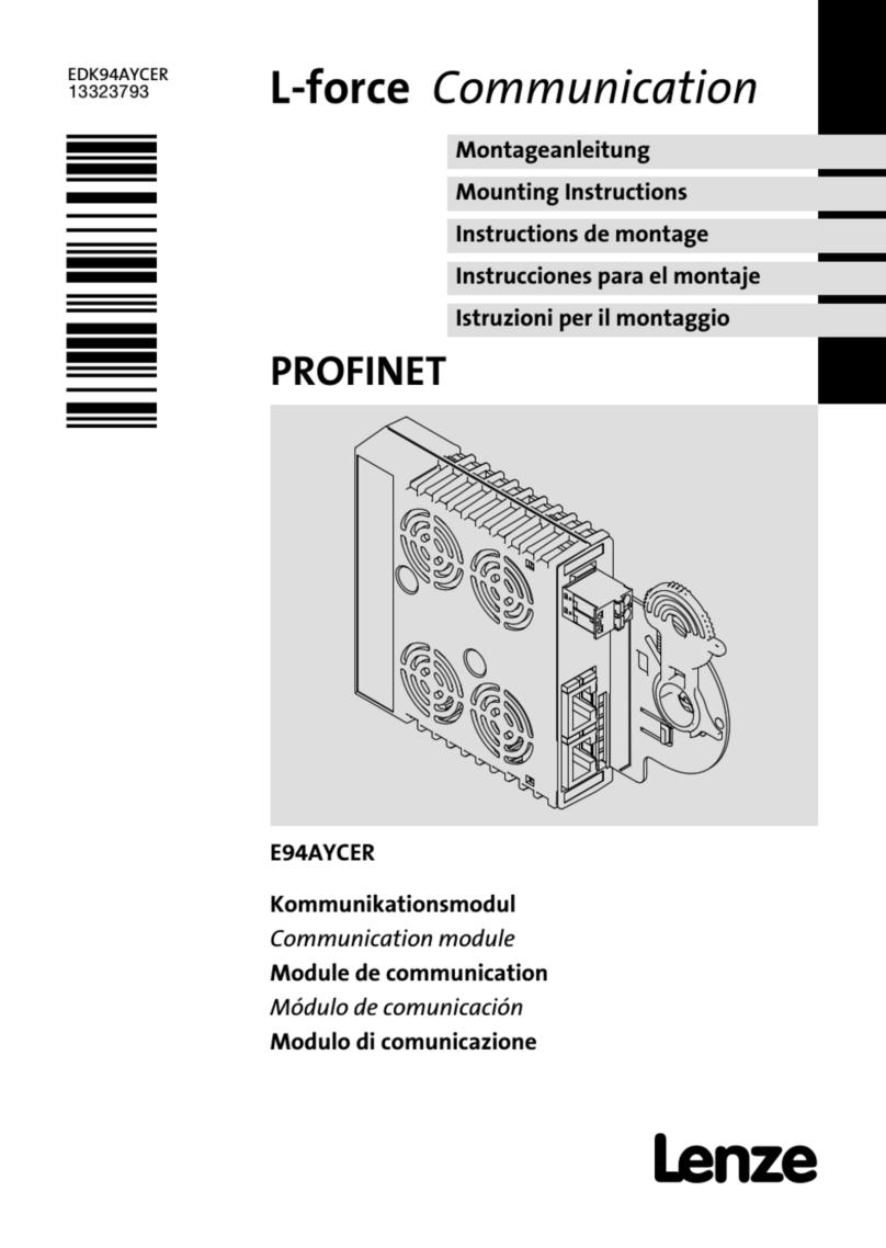
Lenze L-force E94AYCEP User manual

Montageanleitung
Mounting Instructions
Instructions de montage
Instrucciones para el montaje
Istruzioni per il montaggio
EDK94AYCEP
.G<d
Ä.G<dä
Ethernet POWERLINK
E94AYCEP
Kommunikationsmodul
Communication module
Module de communication
Módulo de comunicación
Modulo di comunicazione
L−force Communication

read_de−read_it
Lesen Sie zuerst diese Anleitung, bevor Sie mit den Arbeiten beginnen!
Beachten Sie die enthaltenen Sicherheitshinweise.
Please read these instructions before you start working!
Follow the enclosed safety instructions.
Veuillez lire attentivement cette documentation avant toute action !
Les consignes de sécurité doivent impérativement être respectées.
Lea las instrucciones antes de empezar a trabajar.
Observe las instrucciones de seguridad indicadas.
Prima di usare l’apparecchiatura, leggere le istruzioni contenute in questo
manuale.
Osservare le note di sicurezza.

klappseite E94ZAYCEP−einbaufreiraum
E94YCEP001A
E94YCEP017

EDK94AYCEP DE/EN/FR/ES/IT 4.0
26
legende_kopfzeile−DUMMY_NUM_Reset
Legend for fold−out page
Pos. Description Detailed
information
X210 Connection for external voltage supply
l2−pole plug connector with screw connection 42
X211 Ethernet POWERLINK connections
lRJ45 socket according to IEC 60603−7 39
X212
S233 DIP switches for addressing the node 43
MS
LED status displays for diagnostics 45
ME
BS
BE
DE
0Fig. 0Tab. 0

Contents i
EDK94AYCEP DE/EN/FR/ES/IT 4.0 27
Inhalt
1 About this documentation 28. . . . . . . . . . . . . . . . . . . . . . . . . . . . . . . . . . . . . . . . . . .
Conventions used 29. . . . . . . . . . . . . . . . . . . . . . . . . . . . . . . . . . . . . . . . . . . . . . . . . .
Notes used 30. . . . . . . . . . . . . . . . . . . . . . . . . . . . . . . . . . . . . . . . . . . . . . . . . . . . . . . .
2 Safety instructions 32. . . . . . . . . . . . . . . . . . . . . . . . . . . . . . . . . . . . . . . . . . . . . . . . .
3 Product description 33. . . . . . . . . . . . . . . . . . . . . . . . . . . . . . . . . . . . . . . . . . . . . . . . .
Function 33. . . . . . . . . . . . . . . . . . . . . . . . . . . . . . . . . . . . . . . . . . . . . . . . . . . . . . . . .
Application as directed 33. . . . . . . . . . . . . . . . . . . . . . . . . . . . . . . . . . . . . . . . . . . . . .
Scope of supply 33. . . . . . . . . . . . . . . . . . . . . . . . . . . . . . . . . . . . . . . . . . . . . . . . . . . .
Identification 34. . . . . . . . . . . . . . . . . . . . . . . . . . . . . . . . . . . . . . . . . . . . . . . . . . . . . .
4 Technical data 35. . . . . . . . . . . . . . . . . . . . . . . . . . . . . . . . . . . . . . . . . . . . . . . . . . . . .
General data 35. . . . . . . . . . . . . . . . . . . . . . . . . . . . . . . . . . . . . . . . . . . . . . . . . . . . . .
Dimensions 36. . . . . . . . . . . . . . . . . . . . . . . . . . . . . . . . . . . . . . . . . . . . . . . . . . . . . . .
5 Mechanical installation 37. . . . . . . . . . . . . . . . . . . . . . . . . . . . . . . . . . . . . . . . . . . . .
6 Electrical installation 38. . . . . . . . . . . . . . . . . . . . . . . . . . . . . . . . . . . . . . . . . . . . . . .
Wiring according to EMC 38. . . . . . . . . . . . . . . . . . . . . . . . . . . . . . . . . . . . . . . . . . . .
Ethernet POWERLINK connection 39. . . . . . . . . . . . . . . . . . . . . . . . . . . . . . . . . . . . .
External voltage supply 42. . . . . . . . . . . . . . . . . . . . . . . . . . . . . . . . . . . . . . . . . . . .
7 Commissioning 43. . . . . . . . . . . . . . . . . . . . . . . . . . . . . . . . . . . . . . . . . . . . . . . . . . . .
Before switching on 43. . . . . . . . . . . . . . . . . . . . . . . . . . . . . . . . . . . . . . . . . . . . . . . .
Setting the node address 43. . . . . . . . . . . . . . . . . . . . . . . . . . . . . . . . . . . . . . . . . . .
8 Diagnostics 45. . . . . . . . . . . . . . . . . . . . . . . . . . . . . . . . . . . . . . . . . . . . . . . . . . . . . . .
LED status displays 45. . . . . . . . . . . . . . . . . . . . . . . . . . . . . . . . . . . . . . . . . . . . . . . .
1 About this documentation
EDK94AYCEP DE/EN/FR/ES/IT 4.0
28
H1_Über_die_Doku−TIP_download_EN
1 About this documentation
Contents
This documentation contains ...
ƒ information on the mechanical and electrical installation of the communication
module;
ƒ safety instructions which must be observed by all means;
ƒ information about versions of the Lenze standard devices to be used;
ƒ Information on the LED status displays.
Validity information
The information given in this documentation is valid for the following devices:
Extension module Type designation From hardware version From software version
ETHERNET Powerlink E94AYCEP VA 00.50
Target group
This documentation addresses to persons who project, install, commission, and maintain
the networking and remote maintenance of a machine.
Tip!
Information and auxiliary devices around the Lenze products can be found in
the download area at
http://www.Lenze.com

About this documentation
Conventions used
1
EDK94AYCEP DE/EN/FR/ES/IT 4.0 29
H2_Verw_Konventionen−Verw_Konv_MA_KommModule
Conventions used
This documentation uses the following conventions to distinguish between different types
of information:
Type of information Identification Examples/notes
Numbers
Decimal separator Point The decimal point is used throughout
this documentation.
Example: 1234.56
Symbols
Page reference Reference to another page with
additional information
Example: 16 = see page 16

1 About this documentation
Notes used
EDK94AYCEP DE/EN/FR/ES/IT 4.0
30
H2_Def_Hinweise−SIC_pikt_EN
Notes used
The following pictographs and signal words are used in this documentation to indicate
dangers and important information:
Safety instructions
Structure of safety instructions:
Danger!
(characterises the type and severity of danger)
Note
(describes the danger and gives information about how to prevent dangerous
situations)
Pictograph and signal word Meaning
Danger!
Danger of personal injury through dangerous electrical
voltage.
Reference to an imminent danger that may result in
death or serious personal injury if the corresponding
measures are not taken.
Danger!
Danger of personal injury through a general source of
danger.
Reference to an imminent danger that may result in
death or serious personal injury if the corresponding
measures are not taken.
Stop!
Danger of property damage.
Reference to a possible danger that may result in
property damage if the corresponding measures are not
taken.

2 Safety instructions
EDK94AYCEP DE/EN/FR/ES/IT 4.0
32
H1sic_EN−stop_statEntlad_KommModule
2 Safety instructions
Danger!
Inappropriate handling of the communication module and the standard device
can cause serious personal injury and material damage.
Observe the safety instructions and residual hazards described in the
documentation for the standard device.
Stop!
Electrostatic discharge
Electronic components of the communication module can be damaged or
destroyed through electrostatic discharge.
Possible consequences:
ƒThe communication module is damaged.
ƒFieldbus communication is not possible or faulty.
Protective measures
ƒDischarge electrostatic charges before touching the module.

Product description
Function
3
EDK94AYCEP DE/EN/FR/ES/IT 4.0 33
−H1−TIP zu KHB
3 Product description
Function
The communication module connects Lenze Servo Drives 9400 to the Ethernet POWERLINK
communication system .
Supported functions:
ƒ Managing node (support of up to 50 nodes)
ƒ Controlled node
Application as directed
The communication module ...
ƒ is an accessory module which can be used in conjunction with the following Lenze
standard devices:
Product series Type designation From hardware
version
From software
version
Servo Drives 9400 HighLine E94AxHExxx VB 01.50
Servo Drives 9400 PLC E94AxPExxx VA 02.00
ƒ is a device to be used in industrial power systems.
ƒ can only be used in Ethernet POWERLINK networks.
Any other use shall be deemed inappropriate!
Scope of supply
ƒ E94AYCEP communication module (ETHERNET Powerlink)
ƒ Mounting Instructions
Tip!
Further information regarding this communication module can be found in
the corresponding communication manual.
The PDF file can be found in the download area at
http://www.Lenze.com

3 Product description
Identification
EDK94AYCEP DE/EN/FR/ES/IT 4.0
34
H2_Identifikation−Typbez_E94AYCEP
Identification
E94YCEI003C
E94 A Y C EP VA 0.50
Product series
Device generation
Module identification: extension module
Module type: communication module
Ethernet POWERLINK
Hardware version
Software version

Technical data
General data
4
EDK94AYCEP DE/EN/FR/ES/IT 4.0 35
H1_Daten−GHB Servo Drives 9400
4 Technicaldata
General data
Field Values
Order designation E94AYCEP
Communication profile Ethernet POWERLINK V2
Communication medium S/FTP (Screened Foiled Twisted Pair, ISO/IEC 11801 or EN 50173), CAT
5e
Interface for
communication RJ45: Standard Ethernet (according to IEEE 802.3), 100Base−TX (fast
Ethernet)
Cable length between
2 nodes/hubs max. 100 m
Total cable length Number of nodes x 100 m
Network topology Tree, star, line
Transmission mode Half duplex
Node type lManaging node (support of up to 50 nodes)
lControlled node
Switchable by node address.
Node addresses (Node IDs) l240: E94AYCEP is a managing node.
l1 ... 100: E94AYCEP is a controlled node with another E94AYCEP as
managing node.
l1 239: E94AYCEP is a controlled node with a managing node of a
different manufacturer.
Baud rate 100 MBit/s
Voltage supply External supply via separate power supply unit
l"+": U = 24 V DC (20.4 V...28.8 V), I = 140 mA
l"−": Reference potential for external voltage supply
Conformities, approvals lCE
lUL
"Servo Drives 9400" hardware manual
Here you can find the ambient conditions and the electromagnetic
compatibility (EMC) specifications applying to the communication module.

Mechanical installation 5
EDK94AYCEP DE/EN/FR/ES/IT 4.0 37
H1_MechINS−KommModul Demontage
5 Mechanicalinstallation
Mounting
E94YCXX001G
Dismounting
E94AYCXX001H

6 Electrical installation
Wiring according to EMC
EDK94AYCEP DE/EN/FR/ES/IT 4.0
38
H1_E_INST−EMV_E94AYCEP_LEG
6 Electricalinstallation
Wiring according to EMC
In typical systems, standard shielding of the Ethernet cables is sufficient.
In environments with a very high level of interference, immunity to noise can be improved
by additionally earthing the cable shield on both sides.
Observe the following notes for this:
1. The clearance of the additional earthing from the Ethernet plug depends on the
module slot. The clearance is
– approx. 10 cm for the upper slot (MXI1);
– approx. 20 cm for the lower slot (MXI2).
2. Starting from this clearance, remove the plastic sheath of the cable on a length of
2 cm.
3. Mount the cable shield on the shield sheet of the Servo Drive 9400.
E94YCXX008
Connection to the shield sheet of Servo Drive 9400
Ethernet cable at X211
Ethernet cable at X212
Communication module in slot MXI1 of Servo Drive 9400

Electrical installation
Ethernet POWERLINK connection
6
EDK94AYCEP DE/EN/FR/ES/IT 4.0 39
H2_EthernetAnschluss−Ethernet_KabelSpezifikation
Ethernet POWERLINK connection
You can use a standard Ethernet patch cable for connection to the communication module
(see "Ethernet cable specifications" (41)).
Mounting and dismounting of the Ethernet cables has been optimised for the use of
connectors according to the "Automation Initiative of German Domestic Automobile
Manufacturers" (AIDA).
Note!
Plug/remove the Ethernet cable plug vertically into/from the socket to make
sure that the RJ45 socket will not be damaged.
ƒ The Ethernet POWERLINK connection is made via RJ45 sockets X211 and X212.
ƒ Do not wire, if possible, more than 10 nodes in succession in a network line.
ƒ In case of more than 10 nodes you should deactivate the automatic calculation of the
hub level in the »Engineer« and enter it manually to increase the performance.
ƒ At a cycle time of 1 ms, approx. 25 mandatory nodes can be operated.
– The number of nodes can be increased if the EPL cycle time is increased as well.

6 Electrical installation
Ethernet POWERLINK connection
EDK94AYCEP DE/EN/FR/ES/IT 4.0
40
H2_EthernetAnschluss−Ethernet_KabelSpezifikation
Pin assignment
RJ45 socket PIN Signal
1Tx +
2Tx −
3Rx +
4 −
5 −
6Rx −
7 −
E94YCEP004C 8 −
Tip!
The Ethernet POWERLINK interfaces are equipped with an auto−MDIX function.
This function adapts the polarity of the RJ45 interfaces such that
independently of the polarity of the opposite Ethernet POWERLINK interface
and the cable type used (standard patch cable or crossover cable) a connection
is established.

Electrical installation
Ethernet POWERLINK connection
6
EDK94AYCEP DE/EN/FR/ES/IT 4.0 41
H2_EthernetAnschluss−Ethernet_KabelSpezifikation
Ethernet cable specifications
Note!
Only use cables complying with the below specifications.
Specification of the Ethernet cable
Ethernet standard Standard Ethernet (in accordance with IEEE 802.3), 100Base−TX
(Fast Ethernet)
Cable type S/FTP (Screened Foiled Twisted Pair, ISO/IEC 11801 or EN 50173),
CAT 5e
Damping 23.2 dB (at 100 MHz and per 100 m)
Crosstalk damping 24 dB (at 100 MHz and per 100 m)
Return loss 10 dB (per 100 m)
Surge impedance 100 W

6 Electrical installation
External voltage supply
EDK94AYCEP DE/EN/FR/ES/IT 4.0
42
H2_ext_SpannVersorg−Steckerleiste_Schraubanschl_2pol
External voltage supply
Note!
Always use a separate power supply unit in every control cabinet and safely
separate it according to EN 61800−5−1 ("SELV"/"PELV") in the case of external
voltage supply and larger distances between the control cabinets.
The external voltage supply of the communication module is required if the Ethernet
POWERLINK communication is to be continued in case the supply of the standard device
fails.
Supply the communication module via the 2−pole plug connector (X210) by means of a
separate supply voltage.
Designation Description
+ External voltage supply
V = 24VDC(20.4 V... 28.8 V)
I = 140 mA
−Reference potential for external voltage supply
Terminal data
Field Values
Electrical connection 2−pole plug connector with screw connection
Possible connections Rigid: 1.5 mm2(AWG 16)
Flexible:
Without wire end ferrule
1.5 mm2(AWG 16)
With wire end ferrule, without plastic sleeve
1.5 mm2(AWG 16)
With wire end ferrule, with plastic sleeve
1.5 mm2(AWG 16)
Starting torque 0.5 ... 0.6 Nm (4.4 ... 5.3 lb−in)
Stripping length 6 mm
Table of contents
Other Lenze Conference System manuals

Lenze
Lenze L-force PROFINET E94AYCER User manual

Lenze
Lenze 8400 motec Series Use and care manual

Lenze
Lenze E84DGFCp Series Use and care manual

Lenze
Lenze EDKMF2178IB User manual

Lenze
Lenze AC Tech MotionView OnBoard PositionServo... User manual

Lenze
Lenze EtherNet/IP E84DGFCGFNP Use and care manual

Lenze
Lenze SMVector User manual

Lenze
Lenze E84DGFCR Series Use and care manual

Lenze
Lenze EMF2180IB User manual

Lenze
Lenze E84DGFCp Series Use and care manual