1 CMVCAN01B
Contents
1 Safety Information .............................................................................................................2
1.1 Warnings, Cautions and Notes ......................................................................................... 2
1.1.1 General ...............................................................................................................................2
1.1.2 Application ..........................................................................................................................2
1.1.3 Installation ..........................................................................................................................2
1.1.4 Electrical Connection ..........................................................................................................2
1.1.5 Operation ............................................................................................................................3
1.2 Reference Documentation ................................................................................................ 3
2 Introduction .......................................................................................................................4
2.1 Overview ........................................................................................................................... 4
2.2 SMVector CANopen Implementation Specifications ......................................................... 4
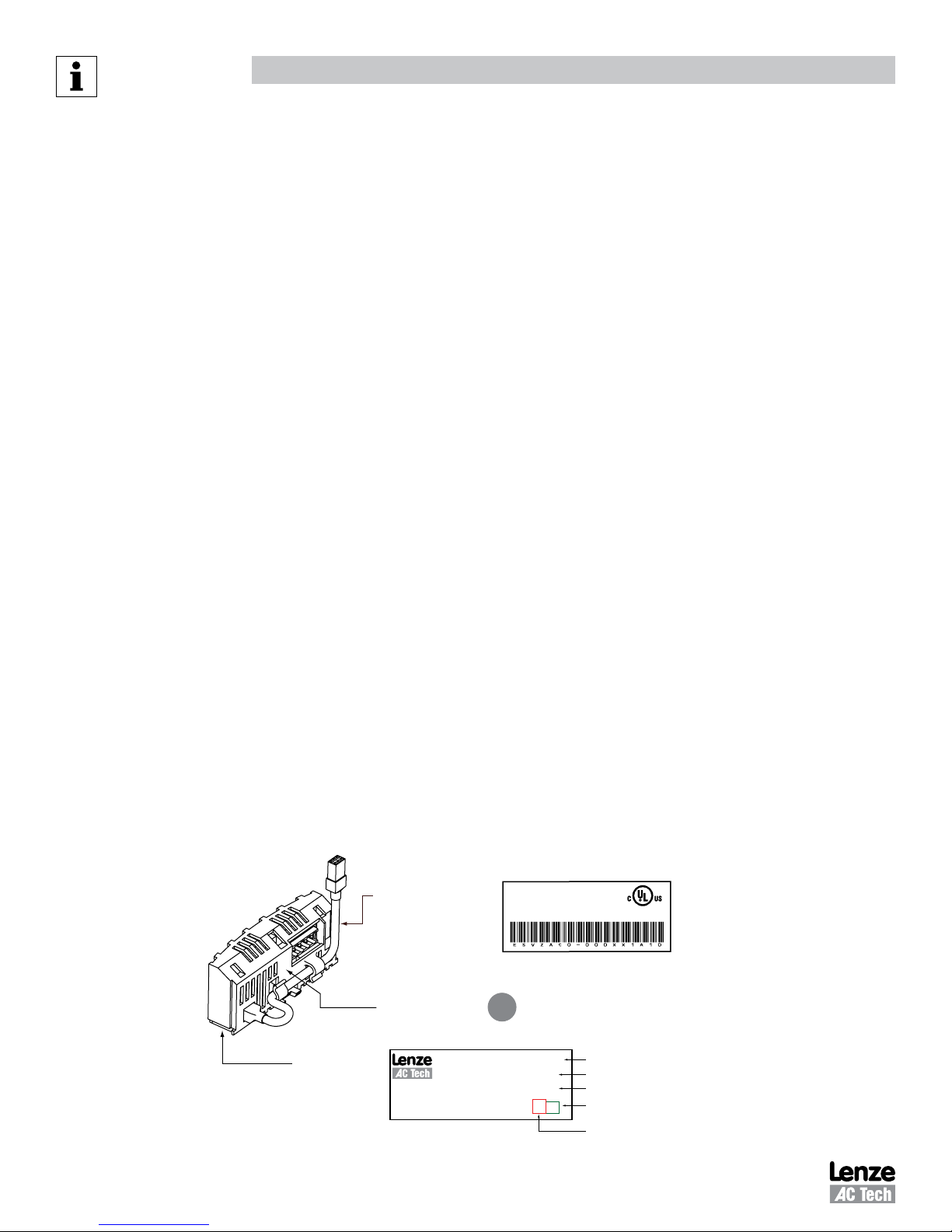
2.3 Module Identification Label ............................................................................................... 4
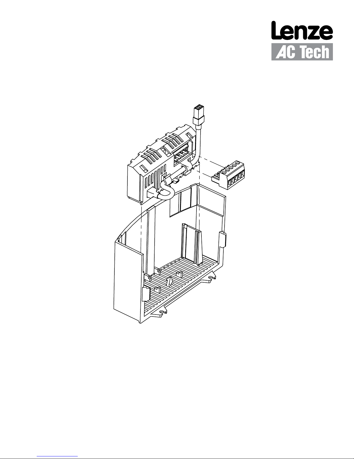
3 Installation .........................................................................................................................5
3.1 Mechanical Installation ...................................................................................................... 5
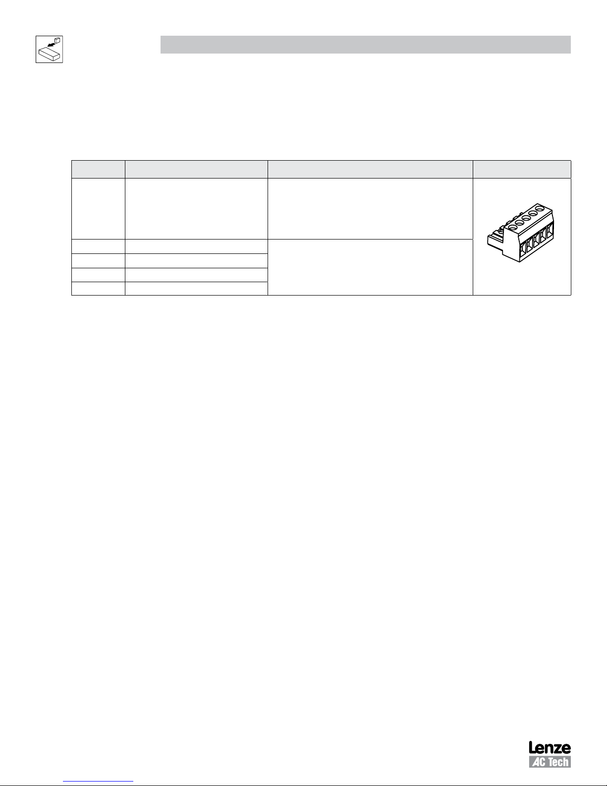
3.2 CANopen Terminal Block .................................................................................................. 6
3.3 Electrical Installation ......................................................................................................... 6
3.3.1 Cable Types .......................................................................................................................6
3.3.2 Network Limitations ............................................................................................................6
3.3.3 Connections and Shielding .................................................................................................7
3.3.4 Network Termination...........................................................................................................8
3.3.5 Network Schematic .............................................................................................................8
4 Commissioning CANopen Communications .....................................................................9
4.1 Quick Set-up ..................................................................................................................... 9
5 Extended Parameters for CANopen ...............................................................................10
5.1 Parameter Menu ............................................................................................................. 10
5.2 CANopen Mapping Details .............................................................................................. 17
5.2.1 RPDO Mapping (P446/P456) ...........................................................................................17
5.2.2 TPDO Mapping (P466/P476) ............................................................................................20
6 Troubleshooting and Fault Elimination ...........................................................................23
6.1 Faults .............................................................................................................................. 23
6.2 Troubleshooting .............................................................................................................. 23
A1 Appendix A - Configuration Example ..............................................................................24
A1.1 Master / Follower Drive System ...................................................................................... 24