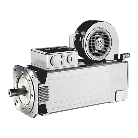
Lenze m500-P Series User manual

.ZCq
Ä.ZCqä
Operating instructions
EN
AC motors m500−P; m540−P; m550−P |
0.75 kW ... 55 kW
Three−phase AC motors
l

,Please read these instructions before you start working!
Follow the safety instructions enclosed.
)Note!
For safety−rated built−on accessories, the manufacturer’s operating
instructions have to be observed!
0Fig. 0Tab. 0

Contents i
3
Lenze ¯ BA 33.0008 ¯ 5.0
1 About this documentation 5. . . . . . . . . . . . . . . . . . . . . . . . . . . . . . . . . . . . . . . . . . . . . . . . . . . . . .
1.1 Document history 5. . . . . . . . . . . . . . . . . . . . . . . . . . . . . . . . . . . . . . . . . . . . . . . . . . . . .
1.2 Conventions used 6. . . . . . . . . . . . . . . . . . . . . . . . . . . . . . . . . . . . . . . . . . . . . . . . . . . . . .
1.3 Terminology used 6. . . . . . . . . . . . . . . . . . . . . . . . . . . . . . . . . . . . . . . . . . . . . . . . . . . . .
1.4 Notes used 7. . . . . . . . . . . . . . . . . . . . . . . . . . . . . . . . . . . . . . . . . . . . . . . . . . . . . . . . . . .
2 Safety instructions 8. . . . . . . . . . . . . . . . . . . . . . . . . . . . . . . . . . . . . . . . . . . . . . . . . . . . . . . . . . . . .
2.1 General safety instructions for drive components 8. . . . . . . . . . . . . . . . . . . . . . . . . . .
2.2 Application as directed 10. . . . . . . . . . . . . . . . . . . . . . . . . . . . . . . . . . . . . . . . . . . . . . . .
2.3 Foreseeable misuse 11. . . . . . . . . . . . . . . . . . . . . . . . . . . . . . . . . . . . . . . . . . . . . . . . . . . .
2.4 Residual hazards 11. . . . . . . . . . . . . . . . . . . . . . . . . . . . . . . . . . . . . . . . . . . . . . . . . . . . . .
2.5 Disposal 12. . . . . . . . . . . . . . . . . . . . . . . . . . . . . . . . . . . . . . . . . . . . . . . . . . . . . . . . . . . . . .
3 Product description 13. . . . . . . . . . . . . . . . . . . . . . . . . . . . . . . . . . . . . . . . . . . . . . . . . . . . . . . . . . . . .
3.1 Identification 13. . . . . . . . . . . . . . . . . . . . . . . . . . . . . . . . . . . . . . . . . . . . . . . . . . . . . . . . .
3.1.1 Motor name 13. . . . . . . . . . . . . . . . . . . . . . . . . . . . . . . . . . . . . . . . . . . . . . . . . .
3.1.2 Motor code 15. . . . . . . . . . . . . . . . . . . . . . . . . . . . . . . . . . . . . . . . . . . . . . . . . . .
3.1.3 Encoder code 16. . . . . . . . . . . . . . . . . . . . . . . . . . . . . . . . . . . . . . . . . . . . . . . . .
3.2.4 Nameplate 17. . . . . . . . . . . . . . . . . . . . . . . . . . . . . . . . . . . . . . . . . . . . . . . . . . .
4 Technical data 19. . . . . . . . . . . . . . . . . . . . . . . . . . . . . . . . . . . . . . . . . . . . . . . . . . . . . . . . . . . . . . . . .
4.1 General data and operating conditions 19. . . . . . . . . . . . . . . . . . . . . . . . . . . . . . . . . .
5 Mechanical installation 20. . . . . . . . . . . . . . . . . . . . . . . . . . . . . . . . . . . . . . . . . . . . . . . . . . . . . . . . .
5.1 Important notes 20. . . . . . . . . . . . . . . . . . . . . . . . . . . . . . . . . . . . . . . . . . . . . . . . . . . . . . .
5.2 Preparation 21. . . . . . . . . . . . . . . . . . . . . . . . . . . . . . . . . . . . . . . . . . . . . . . . . . . . . . . . . . .
5.3 Installation 22. . . . . . . . . . . . . . . . . . . . . . . . . . . . . . . . . . . . . . . . . . . . . . . . . . . . . . . . . . .
5.4 Assembly of built−on accessories 23. . . . . . . . . . . . . . . . . . . . . . . . . . . . . . . . . . . . . . . . .
5.5 Spring−applied brakes 24. . . . . . . . . . . . . . . . . . . . . . . . . . . . . . . . . . . . . . . . . . . . . . . . . .
5.6 Locking of the manual release 25. . . . . . . . . . . . . . . . . . . . . . . . . . . . . . . . . . . . . . . . . . .
6 Electrical installation 27. . . . . . . . . . . . . . . . . . . . . . . . . . . . . . . . . . . . . . . . . . . . . . . . . . . . . . . . . . .
6.1 Important notes 27. . . . . . . . . . . . . . . . . . . . . . . . . . . . . . . . . . . . . . . . . . . . . . . . . . . . . . .
6.2 Three−phase AC motor operation on a frequency inverter 29. . . . . . . . . . . . . . . . . . . .
6.3 EMC−compliant wiring 29. . . . . . . . . . . . . . . . . . . . . . . . . . . . . . . . . . . . . . . . . . . . . . . . . .
6.3.1 Power connections on the terminal board 30. . . . . . . . . . . . . . . . . . . . . . . .
6.3.2 Brake connection to terminal 31. . . . . . . . . . . . . . . . . . . . . . . . . . . . . . . . . . .
6.3.3 Feedback system 32. . . . . . . . . . . . . . . . . . . . . . . . . . . . . . . . . . . . . . . . . . . . . .
6.4 Plug connectors 32. . . . . . . . . . . . . . . . . . . . . . . . . . . . . . . . . . . . . . . . . . . . . . . . . . . . . . .
6.4.1 Motor plug connection assignment 33. . . . . . . . . . . . . . . . . . . . . . . . . . . . . .
6.4.2 Power connections 33. . . . . . . . . . . . . . . . . . . . . . . . . . . . . . . . . . . . . . . . . . . .
6.4.3 Feedback system 36. . . . . . . . . . . . . . . . . . . . . . . . . . . . . . . . . . . . . . . . . . . . . .
6.5 Terminal box HAN connectors 37. . . . . . . . . . . . . . . . . . . . . . . . . . . . . . . . . . . . . . . . . . .
Contentsi
4 Lenze ¯ BA 33.0008 ¯ 5.0
7 Commissioning and operation 40. . . . . . . . . . . . . . . . . . . . . . . . . . . . . . . . . . . . . . . . . . . . . . . . . . .
7.1 Important notes 40. . . . . . . . . . . . . . . . . . . . . . . . . . . . . . . . . . . . . . . . . . . . . . . . . . . . . . .
7.2 Before switching on 40. . . . . . . . . . . . . . . . . . . . . . . . . . . . . . . . . . . . . . . . . . . . . . . . . . .
7.3 Functional test 41. . . . . . . . . . . . . . . . . . . . . . . . . . . . . . . . . . . . . . . . . . . . . . . . . . . . . . . .
7.4 During operation 42. . . . . . . . . . . . . . . . . . . . . . . . . . . . . . . . . . . . . . . . . . . . . . . . . . . . . .
8 Maintenance/repair 43. . . . . . . . . . . . . . . . . . . . . . . . . . . . . . . . . . . . . . . . . . . . . . . . . . . . . . . . . . . .
8.1 Important notes 43. . . . . . . . . . . . . . . . . . . . . . . . . . . . . . . . . . . . . . . . . . . . . . . . . . . . . . .
8.2 Maintenance intervals 43. . . . . . . . . . . . . . . . . . . . . . . . . . . . . . . . . . . . . . . . . . . . . . . . . .
8.2.1 Motor 43. . . . . . . . . . . . . . . . . . . . . . . . . . . . . . . . . . . . . . . . . . . . . . . . . . . . . . .
8.2.2 Encoder 43. . . . . . . . . . . . . . . . . . . . . . . . . . . . . . . . . . . . . . . . . . . . . . . . . . . . .
8.2.3 Spring−operated brakes 44. . . . . . . . . . . . . . . . . . . . . . . . . . . . . . . . . . . . . . . .
8.3 Maintenance operations 44. . . . . . . . . . . . . . . . . . . . . . . . . . . . . . . . . . . . . . . . . . . . . . . .
8.3.1 Motor 44. . . . . . . . . . . . . . . . . . . . . . . . . . . . . . . . . . . . . . . . . . . . . . . . . . . . . . .
8.3.2 Spring−operated brakes 45. . . . . . . . . . . . . . . . . . . . . . . . . . . . . . . . . . . . . . . .
8.3.3 Checking the component parts 46. . . . . . . . . . . . . . . . . . . . . . . . . . . . . . . . . .
8.3.4 Checking the rotor thickness 47. . . . . . . . . . . . . . . . . . . . . . . . . . . . . . . . . . . .
8.3.5 Checking the air gap 47. . . . . . . . . . . . . . . . . . . . . . . . . . . . . . . . . . . . . . . . . .
8.3.6 Release / voltage 48. . . . . . . . . . . . . . . . . . . . . . . . . . . . . . . . . . . . . . . . . . . . . .
8.3.7 Adjusting the air gap 48. . . . . . . . . . . . . . . . . . . . . . . . . . . . . . . . . . . . . . . . . .
8.3.8 Rotor replacement 49. . . . . . . . . . . . . . . . . . . . . . . . . . . . . . . . . . . . . . . . . . . .
8.4 Installation of a spring−applied brake 49. . . . . . . . . . . . . . . . . . . . . . . . . . . . . . . . . . . . .
8.4.1 Brake characteristics 49. . . . . . . . . . . . . . . . . . . . . . . . . . . . . . . . . . . . . . . . . .
8.4.2 Installation of the brake 50. . . . . . . . . . . . . . . . . . . . . . . . . . . . . . . . . . . . . . .
8.4.3 Adjusting the air gap 51. . . . . . . . . . . . . . . . . . . . . . . . . . . . . . . . . . . . . . . . . .
8.4.4 Assembly of the friction plate, sizes 06 to 16 52. . . . . . . . . . . . . . . . . . . . . .
8.4.5 Assembly of the flange 52. . . . . . . . . . . . . . . . . . . . . . . . . . . . . . . . . . . . . . . .
8.4.6 Assembly of the cover seal 53. . . . . . . . . . . . . . . . . . . . . . . . . . . . . . . . . . . . .
8.5 Repair 53. . . . . . . . . . . . . . . . . . . . . . . . . . . . . . . . . . . . . . . . . . . . . . . . . . . . . . . . . . . . . . .
9 Troubleshooting and fault elimination 54. . . . . . . . . . . . . . . . . . . . . . . . . . . . . . . . . . . . . . . . . . . .
10 Appendix 55. . . . . . . . . . . . . . . . . . . . . . . . . . . . . . . . . . . . . . . . . . . . . . . . . . . . . . . . . . . . . . . . . . . . .
10.1 Technical data as specified by ordinances (EU) No. 4/2014 and (EC) No. 640/2009 55

About this documentation
Document history
1
5
Lenze ¯ BA 33.0008 ¯ 5.0
1 About this documentation
Contents
¯ The present documentation is intended for safe working on and with the drives. It
contains safety instructions that must be observed.
¯ All persons working on and with the drives must have the documentation at hand
during work and observe the information and notes relevant for it.
¯ The documentation must always be complete and in a perfectly readable state.
If the information and notes provided in this documentation do not meet your
requirements, please refer to the gearbox documentation.
ITip!
Information and tools concerning the Lenze products can be found in the
download area at
www.lenze.com
Validity
This documentation is valid for three−phase AC motors:
Type Name
m500−P
m540−P
m550−P
Three−phase AC motors (squirrel−cage induction motor)
Target group
This documentation is directed at qualified skilled personnel according to IEC 60364.
Qualified skilled personnel are persons who have the required qualifications to carry out
all activities involved in installing, mounting, commissioning, and operating the
product.
1.1 Document history
Material number Version Description
13493941 1.0 06/2015 TD09 First edition for the pilot series
.ZCq 5.0 05/2019 TD09 Extended by: 0.75kW; motor, B14 type and sizes
080...112
Supplementation of the approvals and Appendix
chapter
Change of the starting torques and power
terminals
.ZCq 5.0 05/2019 TD09 Extended by m54AP motor
13536578 4.0 06/2017 TD09 "Technical data in compliance with ordinances
"(EU) No. 4/2014 or (EC) No. 640/2009" table
changed
.ZCq 5.0 05/2019 TD09 Chapter: Electrical installation − brake
connection, contact identifications have been
added

About this documentation
Conventions used
1
6 Lenze ¯ BA 33.0008 ¯ 5.0
1.2 Conventions used
This documentation uses the following conventions to distinguish different types of
information:
Type of information Writing Example/notes
Numeric notation
Decimal Standard notation Example: 1234
Decimal separator Point The decimal point is always used.
For example: 1234.56
Icons
Page reference ^Reference to another page with additional
information
For instance: ^16 = see page 16
Documentation reference ,Reference to another documentation with
additional information
Example: ,EDKxxx = see EDKxxx documentation
Wildcard LWildcard for options, selection data
1.3 Terminology used
Term Describes the following
Motor Three−phase AC motor (squirrel cage induction motor) in versions
according to product key, ^13 .
Inverter Any servo inverter
Any frequency inverter
Drive system Drive systems including three−phase AC motors and other Lenze drive
components

About this documentation
Notes used
1
7
Lenze ¯ BA 33.0008 ¯ 5.0
1.4 Notes used
The following pictographs and signal words are used in this documentation to indicate
dangers and important information:
Safety instructions
Layout of the safety instructions:
}Danger!
(characterises the type and severity of danger)
Note
(describes the danger and gives information about how to prevent
dangerous situations)
Pictograph and signal word Meaning
{Danger!
Danger of personal injury through dangerous electrical
voltage
Reference to an imminent danger that may result in death
or serious personal injury if the corresponding measures are
not taken.
}Danger!
Danger of personal injury through a general source of
danger
Reference to an imminent danger that may result in death
or serious personal injury if the corresponding measures are
not taken.
(Stop!
Danger of property damage
Reference to a possible danger that may result in property
damage if the corresponding measures are not taken.
Application notes
Pictograph and signal word Meaning
)Note! Important note to ensure trouble−free operation
ITip! Useful tip for easy handling
,Reference to another document

Safety instructions
General safety instructions for drive components
2
8 Lenze ¯ BA 33.0008 ¯ 5.0
2 Safety instructions
2.1 General safety instructions for drive components
At the time of dispatch, the drive components are in line with the latest state of the art
and can be regarded as operationally safe.
Scope
The following general safety instructions apply to all Lenze drive and automation
components.
The product−specific safety and application notes given in this documentation must be
observed!
General hazards
}Danger!
Disregarding the following basic safety measures may lead to severe
personal injury and damage to material assets!
¯ Lenze drive and automation components ...
... must only be used for the intended purpose.
... must never be operated if damaged.
... must never be subjected to technical modifications.
... must never be operated unless completely assembled.
... must never be operated without the covers/guards.
... can − depending on their degree of protection − have live, movable or rotating parts
during or after operation. Surfaces can be hot.
¯ All specifications of the corresponding enclosed documentation must be
observed.
This is vital for safe and trouble−free operation and for achieving the specified
product features.
¯ Only qualified skilled personnel are permitted to work with or on Lenze drive and
automation components.
According to IEC 60364 or CENELEC HD 384, these are persons ...
... who are familiar with the installation, assembly, commissioning and operation of
the product,
... possess the appropriate qualifications for their work,
... and are acquainted with and can apply all the accident prevent regulations,
directives and laws applicable at the place of use.
Storage
¯ In a dry, low−vibration environment without aggressive atmosphere;
¯ In the original packaging;
¯ Protect against dust and impacts;
¯ Observe climatic conditions according to the technical data.

Safety instructions
General safety instructions for drive components
2
9
Lenze ¯ BA 33.0008 ¯ 5.0
Storage conditions
¯ Up to one year:
–Shafts and uncoated surfaces are delivered with rust protection. Aftertreatment
is required where the corrosion protection has been damaged.
¯ More than one year, up to two years:
–Apply a long−term corrosion preventive (e.g. Anticorit BW 366 from the Fuchs
company) to the shafts and uncoated surfaces before storing the motor away.
Transport
Before transport
¯ Make sure that all components are securely mounted;
¯ Make sure that all components with a loose fastening are secured or removed;
¯ Tighten all transport aids (eye bolts or support plates).
Use lifting devices for the transport! (¶20)
(Stop!
Danger by tipping or falling loads!
Observe carrying capacities!
¯ The carrying capacity of the hoists and load handling devices must be
at least the weight of the load, weights (¶LEERER MERKER).
¯ Secure the load to prevent it from tipping over or falling down.
¯ Standing beneath suspended loads is prohibited!
Risk of breakage!
The motors mounted to the gearbox are partly equipped with transport
eyebolts that are solely intended for mounting/dismounting the motor
to/from the gearbox and that must not be used for transport of the
geared motor!
}Danger!
Completely screw in transport aids (such as eye bolts or bearing plates),
they must be flat and applied over their entire surface!
If possible, the transport aids (such as eye bolts or bearing plates) must
be stressed vertically in the direction of the screw axis! Angular tension or
tension to the sides reduces the payload! Observe the information
provided in DIN 580!
Use additional appropriate lifting aids, if required, to achieve a direction
of loading which is as vertical as possible (highest payload). Secure lifting
aids against shifting!
Corrosion protection
Lenze offers paints with different resistance characteristics for drive systems. Since the
resistance may be reduced when the paint coat is damaged, defects in paint work (e.g.
through transport or assembly) must be removed professionally to reach the required
corrosion resistance.

Safety instructions
Application as directed
2
10 Lenze ¯ BA 33.0008 ¯ 5.0
Mechanical installation
¯ Provide for careful handling and avoid mechanical overload. During handling
neither bend components, nor change the insulation distances.
Electrical installation
¯ Carry out the electrical installation according to the relevant regulations (e. g.
cable cross−sections, fusing, connection to the PE conductor). Additional notes are
included in the documentation.
¯ Only plug in or remove pluggable terminals in the deenergised state!
Commissioning
¯ If required, you have to equip the system with additional monitoring and
protective devices in accordance with the respective valid safety regulations (e. g.
law on technical equipment, regulations for the prevention of accidents).
¯ Before commissioning remove transport locking devices and keep them for later
transports.
2.2 Application as directed
All products which this documentation applies to are no household appliances but are
exclusively intended as components for re−utilisation for commercial use or
professional use in terms of IEC/EN 61000−3−2. They meet the requirements of the
Low−Voltage Directive 2006/95/EC and the requirements of the harmonised standards
of the IEC/EN 60034 series.
Only use the products under the operating conditions and power limits specified in this
documentation.
Do not use the brakes installed as fail−safe brakes. It cannot be ruled out that the braking
torque is reduced by disruptive factors which cannot be influenced.
Low−voltage machines with IP23 protection or less are only intended for outdoor use
when applying special protective features.
Products included in the scope of application of the EU regulations (EG) 640/2009
and (EU) 4/2014 (and hence ErP Directive 2009/125/EG) and which did not comply
with minimum efficiency requirements when first put into circulation, are not CE
compliant and will not receive CE marking. The product is for exclusive use outside
the European Economic Area (EEA) only.
Any other use shall be deemed inappropriate!

Safety instructions
Foreseeable misuse
2
11
Lenze ¯ BA 33.0008 ¯ 5.0
2.3 Foreseeable misuse
¯ Do not operate the motors
–... in explosion−protected areas
–... in aggressive environments (acid, gas, vapour, dust, oil)
–... in water
–... in radiation environments
)Note!
Increased surface and corrosion protection can be achieved by using
adapted coating systems.
2.4 Residual hazards
Protection of persons
¯ The motor surfaces can become very hot. Danger of burns when touching!
–Provide protection against accidental contact, if necessary.
¯ Danger of unintentional starting or electrical shocks
–Connections must only be made when the equipment is deenergised and the
motor is at standstill.
–Installed brakes are no fail−safe brakes.
Motor protection
¯ Installed thermal detectors are no full protection for the machine.
–Installed overload protection does not prevent an overload under any
conditions.
¯ Installed brakes are no fail−safe brakes.
–The torque may be reduced by disruptive factors that cannot be influenced such
as contamination by oil.
¯ Fuses are no motor protection.
–Use current−dependent motor protection switches at average operating
frequency.
–Use installed thermal detectors at high operating frequency.
¯ Too high torques cause a fraction of the motor shaft.
–The maximum torques according to catalogue must not be exceeded.
¯ Lateral forces from the motor shaft may occur.
–Align shafts of motor and driving machine exactly to each other.
¯ If deviations from normal operation occur, e.g. increased temperature, noise,
vibration, determine the cause and, if necessary, contact the manufacturer. If in
doubt, switch off the motor.

Product description
Identification
Motor name
3
13
Lenze ¯ BA 33.0008 ¯ 5.0
3 Product description
3.1 Identification
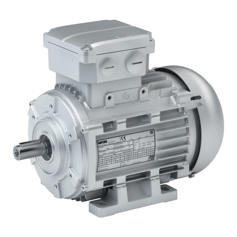
Three−phase AC motors
m550−P
B3 type B5 type B14 type
3.1.1 Motor name
Each motor has a motor name and a motor code. In the sales documents, the motors are
identified by the motor name. The technical documentation and nameplate show the
motor code.
The table below shows a list of the motor names and the first eleven digits of the
corresponding motor code:
m500−P
Motor name Motor code
m500−P132M4 M50AP132M04
m500−P132L4 M50AP132L04
m500−P160M4 M50AP160M04
m500−P160L4 M50AP160L04
m500−P180M4 M50AP180M04
m500−P180L4 M50AP180L04
m500−P180V4 M50AP180V04
m500−P500M4 M50AP500M04
m500−P225M4 M50AP225M04
m500−P225L4 M50AP225L04

Product description
Identification
Motor name
3
14 Lenze ¯ BA 33.0008 ¯ 5.0
m540−P
Motor name Motor code
m540−P90/M4 M54AP090M04
m540−P90/L4 M54AP090L04
m540−P100/M4 M54AP100M04
m540−P100/L4 M54AP100L04
m540−P112/M4 M54AP112M04
m540−P132/M4 M54AP132M04
m540−P132/L4 M54AP132L04
m540−P160/M4 M54AP160M04
m540−P160/L4 M54AP160L04
m540−P180/M4 M54AP180M04
m540−P180/L4 M54AP180L04
m540−P200/M4 M54AP200M04
m540−P225/M4 M54AP225M04
m540−P225/L4 M54AP225L04
m540−P250/M4 M54AP250M04
m550−P
Motor name Motor code
m550−P80/M4 M55AP080M04
m550−P90/M4 M55AP090M04
m550−P90/L4 M55AP090L04
m550−P100/M4 M55AP100M04
m550−P100/L4 M55AP100L04
m550−P112/M4 M55AP112M04
m550−P132/M4 M55AP132M04
m550−P132/L4 M55AP132L04
m550−P160/M4 M55AP160M04
m550−P160/L4 M55AP160L04
m550−P180/M4 M55AP180M04
m550−P180/L4 M55AP180L04
m550−P180/V4 M55AP180V04
m550−P200/M4 M55AP200M04
m550−P225/M4 M55AP225M04
m550−P225/L4 M55AP225L04

Product description
Identification
Motor code
3
15
Lenze ¯ BA 33.0008 ¯ 5.0
3.1.2 Motor code
m500−P / m540−P / m550−P three−phase AC motors
Example m50A− P 132 M 4 S E F 0 C T
Meaning Variant
Efficiency class Premium − IE3 P
Size 080
090
100
112
132
160
180
200
225
Overall length Very short K
Abbr. S
Medium M
Long L
Very long V
Number of poles 4−pole 04
Enclosure IP54/55 5
Cooling Self−ventilation E
Forced ventilation F
No ventilation S
Brake attachment No brake 0
Spring−applied
brake
F
Act. value
encoder
No encoder 0
Incremental
encoder
E
Resolver R
Absolute value
encoder
A
Approvals CE UL R
CE UL−CSA V
CE CSA S
QC
CE CCC 3
None N
UL−CSA V
CCC 4
CE UL−CSA CCC W
UL−CSA CCC Y
Design
version
Internal key T

Product description
Identification
Encoder code
3
16 Lenze ¯ BA 33.0008 ¯ 5.0
3.1.3 Encoder code
Encoder code
Example SFC 1024 − 8V − K 2
Meaning Type Encoder code
Product line Resolver RS
Resolver for safety function RV
Incremental encoder IG
Incremental encoder with commutation signal IK
Singleturn absolute value encoder SFC
Multitum absolute value encoder AM
Number 2−pole resolver for servo motors 0
2−pole resolver for three−phase AC motors 1
Number of pole pairs for resolvers 2, 3, 4,...
Number of steps / increments per revolution 32, 128,
512,
1024,
2048, ...
Voltage Medium supply voltage
−
5V, 8V,
15V,
24V, ...
Interface or
signal level
Standard
−
TTL T
HTL (for incremental encoders) H
Hiperface (for absolute value encoders) H
EnDat E
sin/cos 1 Vss S
For safety function
TTL U
HTL (for incremental encoders) K
Hiperface (for absolute value encoders) K
EnDat F
sin/cos 1 Vss V
Safety integration level (SIL) 1
2
3
4
)Note!
If feedback systems for safety functions are used, the manufacturer’s
documentation must be observed!

Product description
Nameplate
3
17
Lenze ¯ BA 33.0008 ¯ 5.0
3.1.4 Nameplate
Geared motor with a directly mounted motor (layout A)
L
C86
cos j
Hz
kW
r/min
V
A
1
16.1
16.2
16.3
10.2
8.1
15
8.2 8.3
11
16.4
16.5
16.6
16.4
16.5
h%
10.3
9
2
3
4
67.1 7.2
5.1
5.3
5.2
5.4
18
27
14.3
14.2
14.1
13
23
16.7
22
26
19
15
17
21
20.1
Geared motor with a directly mounted motor (layout B, with QR code)
L
h%
cos j
Hz
kW
r/min
V
A
9
2
1
16.1
16.2
16.3
18
15
14.1
11
16.4
16.5
16.6
16.7
16.4
16.5
5.4
5.2
C86
14.3
17
30
5.3
5.1
4
3
7.2
7.1
6
33.1
8.1 8.2 8.3
20.1
10.2 10.3
43
23 13 14.2
22
33.2
21
Three−phase AC motor with a standard output flange
L
h%
cos j
Hz
kW
r/min
V
A
9
2
1
4
16.1
16.2
16.3
9
22
8.1
24
18
14.2
15
21
8.2 8.3
23 26
14.1
11
10.2 10.3
16.4
16.5
16.6
16.7
27
14.3
16.4
16.5
13
20.1

Product description
Nameplate
3
18 Lenze ¯ BA 33.0008 ¯ 5.0
Pos. Contents
1Manufacturer / production location
2Type of motor / standard
3Gearbox type
4Motor type
5Technical data
5 5.1 Ratio
5 5.2 Rated torque
5 5.3 Rated speed
5 5.4 Rated frequency
6Position of system modules / mounting position
7Lubricant details
7 7.1 Lubricant amount
7 7.2 Lubricant type
8Brake data
8 8.1 Type
8 8.2 AC/DC brake voltage
8 8.3 Braking torque, electrical power input
9For feedback / pulse encoder or resolver data, ^16
10 Production data
10 10.2 Material number
10 10.3 Serial number
11 Bar code
13 Information with regard to the operating mode
14 Additional motor specifications
14 14.1 Temperature class
14 14.2 Enclosure
14 14.3 Motor protection
15 Applicable conformities, approvals and certificates
16 Rated data for various frequencies
16 16.1 Hz = frequency
16 16.2 kW = motor power
16 16.3 rpm = motor speed
16 16.4 V = motor voltage
16 16.5 A = motor current
16 16.6 cos j= motor power factor
16 16.7 h= motor efficiency: at a rated power of 100%
17 Application factor / load capacity
18 Year of manufacture / week of manufacture
19 UL file number
20 Customer data
20 20.1 Additional customer data
21 UL category (e.g. inverter duty motor)
22 C86 = motor code for inverter parameterisation (code 0086)
23 Efficiency class
24 Partial load efficiencies for 50Hz operation at a rated power of 50% and 75%
26 CC number Department of Energy (optional)
27 Permissible ambient temperature (e.g. Ta £40°C)
30 Weight
43 Internal key: QR code

Technical data
General data and operating conditions
4
19
Lenze ¯ BA 33.0008 ¯ 5.0
4 Technical data
4.1 General data and operating conditions
General data
Conformity and approval
Conformity
CE 2014/35/EU Low−Voltage Directive
2009/125/EC ErP Directive
Regulation No. 4/2014 and No. 640/2009 on the
ecodesign of electric motors
2014/30/EU EMC Directive
EAC TP TC 004/2011
(TR CU 004/2011)
On safety of low voltage
equipment
Eurasian Conformity
TR CU: Technical Regulation of
Customs Union
EAC TP TC 020/2011
(TR CU 020/2011)
Electromagnetic
compatibility of technical
means
Eurasian Conformity
TR CU: Technical Regulation of
Customs Union
Approvals
UL UL 1004−8 File No. E210321 Inverter Duty Motors
Motors and Generators
CSA CSA C22.2 No. 100
Energy Verified CFR Part 431.23 File No. E210321
CC1278B
Energy Efficiency Program for
Certain Commercial and
Industrial Equipment
CSA C390−10 Energy Efficiency Test
Methods for Three−Phase
Induction Motors
CCC GB Standard
12350−2009
Safety requirements of small−power motors
The applicable approvals for the product you have ordered require labelling and are
specified on the nameplate.
Protection of persons and devices
Enclosure IEC/EN 60034−5 See nameplate
Degrees of protection only apply to horizontal installation
All unused connectors must be closed with protection
covers or blanking plugs.
Temperature class F (155 °C)
IEC/EN 60034−1
Exceedance of the temperature limit weakens or destroys
the insulation
Operating conditions
Ambient conditions
Climatic
Transport IEC/EN 60721−3−2 2K3 (−20 °C ... +70 °C)
Storage IEC/EN 60721−3−1 1K3 (−20 °C ... +60 °C) < 3 months
1K3 (−20 °C ... +40 °C) > 3 months
Operation IEC/EN 60721−3−3 3K3 (−20 °C ... +40 °C) Without brake
3K3 (−10 °C ... +40 °C) With brake
> +40 °C With power reduction, see
catalogue
Site altitude < 1000 m amsl − without power reduction
> 1000 m amsl < 4000m amsl with power reduction, see
catalogue
Humidity Relative humidity £85 %, without condensation
Mechanical
IEC/EN60721−3−3 3M6

Mechanical installation
Important notes
5
20 Lenze ¯ BA 33.0008 ¯ 5.0
5 Mechanical installation
5.1 Important notes
}Danger!
Some of the motors mounted to the gearboxes are equipped with
transport aids. They are only intended for the mounting/dismounting of
the motor to the gearbox and must not be used for the entire geared
motor!
¯ Only move the drive with means of transport or hoists that have sufficient
load−bearing capacity.
¯ Ensure safe fixing.
¯ Avoid shocks!
Screw−on dimensions B14 flange
(Stop!
Observe the maximally permissible screw−in depth for B14 flange!
S
C
c max. s
[mm] [mm]
M55AP080L0LFT100 10 M6
FT130 12 M8
M55AP090L0LFT115 16 M8
FT130 12 M8
M55AP100L0LFT130 12 M8
M55AP112L0LFT130 12 M8
This manual suits for next models
43
Table of contents
Other Lenze Engine manuals