manuals.online logo
Brands
  1. Home
  2. •
  3. Brands
  4. •
  5. Leviton
  6. •
  7. Cables And Connectors
  8. •
  9. Leviton 20A User manual

Leviton 20A User manual

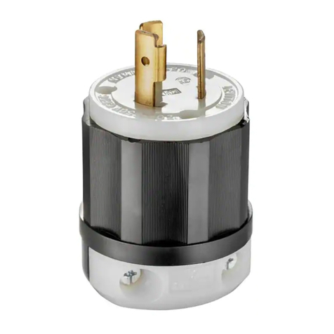
Watertight Pin and Sleeve
Plugs and Connectors
20A, 30A, 60A and 100A
QUICK INSTALL GUIDE ENGLISH
PK-A3278-10-00-0A
WARNINGS
• TO AVOID FIRE SHOCK, OR DEATH, TURN OFF POWER AT CIRCUIT BREAKER OR FUSE,
TEST THAT POWER IS OFF BEFORE SERVICING OR WIRING and ensure connections are
made in the same sequence as existing device connections.
• These devices conform to IEC standard 60309-1 and 60309-2. The construction is such that
each device cannot be mated with another IEC device of different specifications (i.e., voltage,
amperage or system rating). For safety purposes, do not use a non-IEC device with these pin
and sleeve devices. The specifications for non-IEC devices are established by the individual
manufacturers, and may not meet IEC standards. IMPROPER MATING OF DEVICES MAY
CAUSE FIRE, SHOCK OR DEATH.
CAUTIONS
• Examine devices periodically for any foreign matter that may contaminate the contacts or the insulation material
separating the contacts. Contamination decreases the device’s insulation properties. This increases the
potential for arcing and possibly decreases the product’s life and may cause fire and/or shock hazard. The
frequency of inspection depends upon the degree of contamination.
• If you are unsure about any part of these instructions, consult an electrician.
• To be installed and/or used in accordance with electrical codes and regulations (Including NEC/CEC, as applicable).
• Use this device only with copper or copper clad wire.
© 2019 Leviton Mfg. Co., Inc.
20A and 30A Plug Installation 20A and 30A Connector Installation
housing
contact carrier
saddle
clamp
saddle
clamp screw
quick lock
pin
saddle clamp assembly
OR
screwless clamp assembly
dust shield
housing
contact carrier
1. Unscrew assembly and contact carrier.
assembly
screws
2. Thread wire.
Remove washer from housing, select grommet (Table 1) thread clamp assembly, washer, grommet and
housing onto selected wire (Table 3).
NOTE: If using screwless clamp assembly, select strain relief nut first (Table 2).
OR
strain relief
nut washer grommet
3. Wire.
Cut and strip cable jacket and conductors (Table 4).
WARNING: TO AVOID FIRE, SHOCK OR DEATH, connections must be made in the same sequence as
existing device connections.
Connect wires (Table 5 and Stripping and Wiring Diagram) and tighten terminal screws. NOTE: Reference
torque value (Table 6). Allen key included.
quick lock
pin
housing
contact carrier
saddle clamp
saddle clamp
screw
saddle clamp assembly
OR
screwless clamp assembly
dust shield
housing
contact carrier
quick lock
pin
quick lock
pin
1. Unscrew assembly and contact carrier.
assembly
screws
OR
washer grommet
2. Thread wire.
Remove washer from housing, select grommet (Table 1) thread clamp assembly, washer, grommet and
housing onto selected wire (Table 3).
NOTE: If using screwless clamp assembly, select strain relief nut first (Table 2).
strain relief
nut
3. Wire.
Cut and strip cable jacket and conductors (Table 4).
WARNING: TO AVOID FIRE, SHOCK OR DEATH, connections must be made in the same sequence as
existing device connections.
Connect wires (Table 5 and Stripping and Wiring Diagram) and tighten terminal screws. NOTE: Reference
torque value (Table 6). Allen key included.
4. Reconnect contact carrier.
Tighten assembly screws (Table 6).
4. Reconnect contact carrier.
Tighten assembly screws (Table 6).
NOTE: Line up key with key notch.
NOTE: fully engaged quick lock pin
5. Reassemble.
Slide grommet and washer down and seat firmly into housing. Slide saddle clamp assembly or screwless
clamp assembly onto housing and screw on until quick lock pin fully engages. Tighten clamp screws
(Table 6).
OR
OR
5. Reassemble.
Slide grommet and washer down and seat firmly into housing. Slide saddle clamp assembly or screwless
clamp assembly onto housing and screw on until quick lock pin fully engages. Tighten clamp screws
(Table 6).
NOTE: fully engaged quick lock pin
WEB VERSION
PK-A3278-10-00-0A© 2019 Leviton Mfg. Co., Inc. For Technical Assistance Call: 1-800-824-3005 (USA Only) or 1-800-405-5320 (Canada Only) www.leviton.com
4. Reconnect contact carrier. 4. Reconnect contact carrier.
20A 3-4 Wire Strain Relief Nut
& Dust Shield Usage
Amperage Wire Diameter
(in)
Wire Diameter
(mm)
Strain Relief
Nut & Dust
Shield Marking
20A
0.300 - 0.425 7.620 -10.795 V
0.425 - 0.550 10.795 -13.970 W
0.550 - 0.675 13.970 - 17.145 X
0.675 - 0.860 17.145 - 21.844 Y
20 A 5 Wire & 30A 3, 4 and 5 Wire
Strain Relief Nut & Dust Shield Usage
20A & 30A
0.325 - 0.500 8.255 - 12.700 T
0.500 - 0.625 12.700 - 15.875 S
0.625 - 0.750 15.875 - 19.050 R
0.750 - 0.875 19.050 - 22.225 Q
0.875 - 1.000 22.225 - 25.400 P
1.000 - 1.125 25.400 - 28.575 O
2
20A 3-4 Wire Grommet Usage
Amperage Wire Diameter
(in)
Wire Diameter
(mm)
Grommet
Marking
20A
0.300 - 0.425 7.620 -10.795 V
0.425 - 0.550 10.795 -13.970 W
0.550 - 0.675 13.970 - 17.145 X
0.675 - 0.860 17.145 - 21.844 Y
20A 5 Wire & 30A 3,4, 5 Wire Grommet Usage
20A & 30A
0.325 - 0.500 8.255 - 12.700 T
0.500 - 0.625 12.700 - 15.875 S
0.625 - 0.750 15.875 - 19.050 R
0.750 - 0.875 19.050 - 22.225 Q
0.875 - 1.000 22.225 - 25.400 P
1.000 - 1.125 25.400 - 28.575 O
60A Grommet Usage
60A
0.600 - 0.725 15.240 - 18.415 N
0.725 - 0.850 18.415 - 21.590 M
0.850 - 0.975 21.590 - 24.765 L
0.975 - 1.163 24.765 - 29.540 K
1.163 - 1.350 29.540 - 34.290 J
1.350 - 1.475 34.290 - 37.465 I
1.475 - 1.600 37.465 - 40.640 H
100A Grommet Usage
100A
0.725 - 0.850 18.415 - 21.590 A
0.850 - 0.975 21.590 - 24.765 B
0.975 - 1.163 24.765 - 29.540 C
1.163 - 1.350 29.540 - 34.290 D
1.350 - 1.475 34.290 - 37.465 E
1.475 - 1.600 37.465 - 40.640 F
1Terminal identification Chart
and green color Equipment ground conductor
N and white color Grounded circuit conductors (neutral)
L1, L2, L3 Ungrounded circuit conductors (line, hot)
Pilot Control circuit conductor.
5
Wire Sizes
Device
From To Grip Range
Min./Max.
Wire Diam. (in)
Grip Range
Min./Max.
Wire Diam.
(mm)
AWG COND TYPE AWG COND TYPE
20A #14
3
S
#10
3
S 0.330/0.830 8/2144
55
30A #12
3
#8
3
S or W 0.580/1.125 15/2944
55
60A #8
3
S or
W#2
3
W
0.875/1.450 22/37
44
55
100A #6
3
W#0
3
0.725/1.600 18/41
44
55
3
Screw Tightening Guide in-lbs (N-m)
Device Terminal
Screws
Pilot Terminal
Screws
Assembly
Screws
Cable Clamp
Screws
20A
20 (2.26) N/A 8 (0.9)
10 (1.13)
30A
60A
50 (5.65) 20 (2.26) N/A
100A 15 (1.69)
6
FOR CANADA ONLY
For warranty information and/or product returns, residents of Canada should contact Leviton in writing at Leviton Manufacturing of Canada Ltd to the attention of the Quality Assurance Department, 165 Hymus Blvd, Pointe-
Claire (Quebec), Canada H9R 1E9 or by telephone at 1 800 405-5320.
1. Unscrew saddle clamp assembly and contact carrier.
2. Thread wire.
Remove washer from housing, select grommet (Table 1) thread clamp assembly, washer, grommet and
housing onto selected wire (Table 3).
3. Wire.
Cut and strip cable jacket and conductors (Table 4).
WARNING: TO AVOID FIRE, SHOCK OR DEATH, connections must be made in the same sequence as
existing device connections.
Connect wires (Table 5 and Stripping and Wiring Diagram) and tighten terminal screws. NOTE: Reference
torque value (Table 6). Allen key included.
5. Reassemble.
Slide grommet and washer down and seat firmly into housing. Slide saddle clamp assembly or screwless
clamp assembly onto housing and screw on until quick lock pin fully engages. Tighten clamp screws
(Table 6).
2. Thread wire.
Remove washer from housing, select grommet (Table 1) thread clamp assembly, washer, grommet and
housing onto selected wire (Table 3).
1. Unscrew saddle clamp assembly and contact carrier.
3. Wire.
Cut and strip cable jacket and conductors (Table 4).
WARNING: TO AVOID FIRE, SHOCK OR DEATH, connections must be made in the same sequence as
existing device connections.
Connect wires (Table 5 and Stripping and Wiring Diagram) and tighten terminal screws. NOTE: Reference
torque value (Table 6). Allen key included.
5. Reassemble.
Slide grommet and washer down and seat firmly into housing. Slide saddle clamp assembly or screwless
clamp assembly onto housing and screw on until quick lock pin fully engages. Tighten clamp screws
(Table 6).
NOTE: fully engaged quick lock pin NOTE: fully engaged quick lock pin
Cable and Wire Stripping Guide
Device No. Wires Conductor
Cable Jacket (A) Conductor (B)
Inches mm Inches mm
20A
All All
1.375 35 0.375 10
30A 1.625 41 0.625 16
60A 3 76 125
100A 3.5 89 125
4
Cable Jacket
Hot conductors
(no specific color identification)
Green equipment
grounding conductor
only (or green with
yellow stripes).
White or gray,
system ground or
neutral conductor only.
L2
L1
White dot and N
L3
Green dot and
A
B
(SeeTable 4)
Stripping and Wiring Diagram
60A and 100A Plug Installation 60A and 100A Connector Installation
LIMITED 5 YEAR WARRANTY AND EXCLUSIONS
Leviton warrants to the original consumer purchaser and not for
the benefit of anyone else that this product at the time of its sale
by Leviton is free of defects in materials and workmanship under
normal and proper use for three years from the purchase date.
Leviton’s only obligation is to correct such defects by repair or
replacement, at its option. For details visit www.leviton.com or
call 1-800-824-3005. This warranty excludes and there is disclaimed
liability for labor for removal of this product or reinstallation. This
warranty is void if this product is installed impro perly or in an
improper environment, overloaded, misused, opened, abused,
or altered in any manner, or is not used under normal operating
conditions or not in accordance with any labels or instructions.
There are no other or implied warranties of any kind, including
merchantability and fitness for a particular purpose, but if any
implied warranty is required by the applicable jurisdiction, the duration
of any such implied warranty, including merchantability and fitness for
a particular purpose, is limited to five years. Leviton is not liable for
incidental,indirect,special,orconsequentialdamages,including
without limitation, damage to, or loss of use of, any equipment,
lost sales or profits or delay or failure to perform this warranty
obligation. The remedies provided herein are the exclusive remedies
under this warranty, whether based on contract, tort or otherwise.
WEB VERSION

This manual suits for next models

3

Other Leviton Cables And Connectors manuals

Leviton 3W101 User manual

Leviton

Leviton 3W101 User manual

Leviton dustguard 15 User manual

Leviton

Leviton dustguard 15 User manual

Leviton 5G110-RX5 User manual

Leviton

Leviton 5G110-RX5 User manual

Leviton 476TM-652 User manual

Leviton

Leviton 476TM-652 User manual

Leviton Lev-Lok MT528-I User manual

Leviton

Leviton Lev-Lok MT528-I User manual

Leviton 48642 User manual

Leviton

Leviton 48642 User manual

Leviton NE100-00C User manual

Leviton

Leviton NE100-00C User manual

Leviton 275 User manual

Leviton

Leviton 275 User manual

Leviton J1772 User manual

Leviton

Leviton J1772 User manual

Leviton QuickPort USOC Snap-In Connector 41106-R*6 User manual

Leviton

Leviton QuickPort USOC Snap-In Connector 41106-R*6 User manual

Leviton 476TM-612 Installation instructions manual

Leviton

Leviton 476TM-612 Installation instructions manual

Leviton Quickport 40813 Series User manual

Leviton

Leviton Quickport 40813 Series User manual

Leviton 40951-1PW User manual

Leviton

Leviton 40951-1PW User manual

Leviton 5G108-R User manual

Leviton

Leviton 5G108-R User manual

Leviton Lev-Lok MT528 User manual

Leviton

Leviton Lev-Lok MT528 User manual

Leviton Opt-X SDX 5WLRG-12C User manual

Leviton

Leviton Opt-X SDX 5WLRG-12C User manual

Leviton black & white 3762 User manual

Leviton

Leviton black & white 3762 User manual

Leviton 21414-LB User manual

Leviton

Leviton 21414-LB User manual

Leviton 47690-04C User manual

Leviton

Leviton 47690-04C User manual

Leviton Black & White 2421 User manual

Leviton

Leviton Black & White 2421 User manual

Leviton 41644 Series User manual

Leviton

Leviton 41644 Series User manual

Leviton 5S180-SH5 User manual

Leviton

Leviton 5S180-SH5 User manual

Leviton QuickPort Duplex 106 User manual

Leviton

Leviton QuickPort Duplex 106 User manual

Leviton 40735-R User manual

Leviton

Leviton 40735-R User manual

Popular Cables And Connectors manuals by other brands

Philips SWV6434 Specifications

Philips

Philips SWV6434 Specifications

Rockwell Automation Allen-Bradley 800G-ACGK1 installation instructions

Rockwell Automation

Rockwell Automation Allen-Bradley 800G-ACGK1 installation instructions

Lenze EWS Mounting instructions

Lenze

Lenze EWS Mounting instructions

Comprehensive CSW-VG440A user manual

Comprehensive

Comprehensive CSW-VG440A user manual

Champion CHWC301 user manual

Champion

Champion CHWC301 user manual

DREXAN CMH-CON installation instructions

DREXAN

DREXAN CMH-CON installation instructions

CNC4PC C86ACCP user manual

CNC4PC

CNC4PC C86ACCP user manual

Waterworks PowerUP HD manual

Waterworks

Waterworks PowerUP HD manual

RF-Link HSP-5012 user manual

RF-Link

RF-Link HSP-5012 user manual

Eaton 600 A 35 kV Class Insulated Standoff Bushing installation instructions

Eaton

Eaton 600 A 35 kV Class Insulated Standoff Bushing installation instructions

Panduit IAEBH5E installation instructions

Panduit

Panduit IAEBH5E installation instructions

Sony VMC-P10 instructions

Sony

Sony VMC-P10 instructions

Rockwell Automation Allen-Bradley 1794-TB2 installation instructions

Rockwell Automation

Rockwell Automation Allen-Bradley 1794-TB2 installation instructions

Sirius Satellite Radio 14255 installation guide

Sirius Satellite Radio

Sirius Satellite Radio 14255 installation guide

Philips SWA3427W Specifications

Philips

Philips SWA3427W Specifications

Tyco Electronics AMP instruction sheet

Tyco Electronics

Tyco Electronics AMP instruction sheet

Aukey CB-CD2 user manual

Aukey

Aukey CB-CD2 user manual

NTI VOPEX-HDS-x Installation and operation manual

NTI

NTI VOPEX-HDS-x Installation and operation manual

manuals.online logo
manuals.online logoBrands
  • About & Mission
  • Contact us
  • Privacy Policy
  • Terms and Conditions

Copyright 2025 Manuals.Online. All Rights Reserved.