manuals.online logo
Brands
  1. Home
  2. •
  3. Brands
  4. •
  5. Leviton
  6. •
  7. Security Sensor
  8. •
  9. Leviton ODC Series User manual

Leviton ODC Series User manual

FEATURES
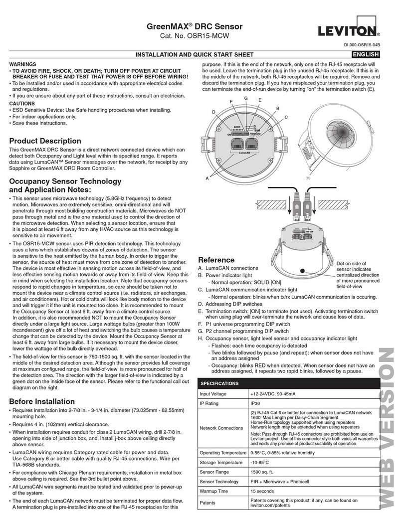
• Sensor has a 360°field-of-view with 530 sq. ft. of coverage.
• LED indicator light blinks when sensor detects motion.
• Cat. Nos. ODC0S-I1 and ODC0S-I7 have four 14AWG 6" pre-stripped color coded leads.
• Screw on cover plate shields mounting hardware and adjustment control.
DESCRIPTION
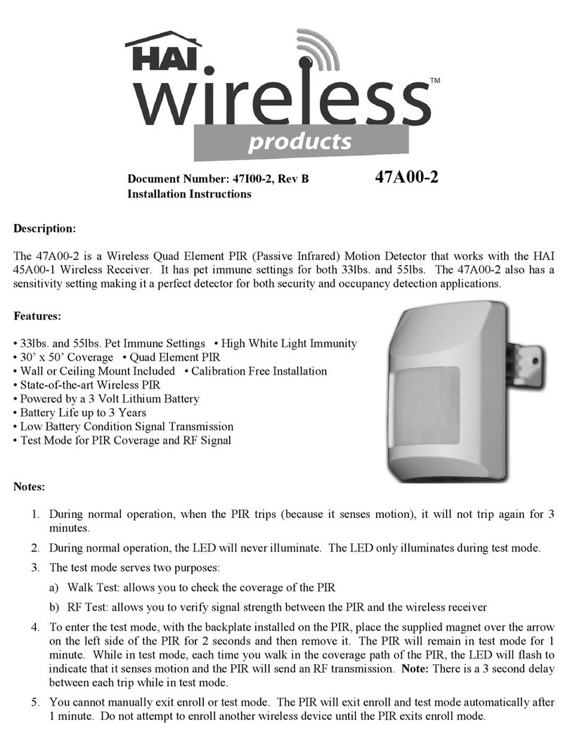
The Leviton Passive Infrared Ceiling Mount Occupancy Sensor, Cat. Nos. ODC0S-I1 and ODC0S-I7, monitors
rapid changes in temperature within its field-of-view (see Figures 3 and 4) and is designed to turn lights ON when
temperature changes (such as a person entering a room) is detected, and OFF when occupancy is no longer
detected and the scheduled time-delay setting has expired.
Since Cat. Nos. ODC0S-I1 and ODC0S-I7 respond to temperature changes, care should be taken not to mount the
sensor directly above a heat source, or where hot/cold drafts (i.e. from an HVAC duct) will blow directly on the
sensor, or where adjacent traffic, (i.e. hallway activity) will be within the sensor’s field-of-view.
In addition, it is also recommended NOT to mount the Occupancy Sensor directly under a large light source. Large
wattage bulbs (greater than 100W incandescent) give off a lot of heat and switching the bulb causes a temperature
change that can be detected by the device. Mount the Occupancy Sensor at least 6 ft. away from large bulbs.
INSTALLATION INSTRUCTIONS
WARNING: TO BE INSTALLED AND/OR USED IN ACCORDANCE WITH APPROPRIATE ELECTRICAL CODES
AND REGULATIONS.
WARNING: IF YOU ARE NOT SURE ABOUT ANY PART OF THESE INSTRUCTIONS, CONSULT A QUALIFIED
ELECTRICIAN.
WARNING: TO AVOID OVERHEATING AND POSSIBLE DAMAGE TO THIS DEVICE AND OTHER EQUIPMENT,
DO NOT INSTALL TO CONTROL A TRANSFORMER-OPERATED DEVICE(S) OTHER THAN APPROPRIATE
LOW-VOLTAGE LIGHTING.
OTHER CAUTIONS:
1. USE THIS DEVICE ONLY WITH COPPER OR COPPER CLAD WIRE. WITH ALUMINUM WIRE USE ONLY
DEVICES MARKED CO/ALR OR CU/AL.
2. DO NOT ATTEMPT TO DISASSEMBLE OR REPAIR. DISCONNECT POWER WHEN SERVICING OR
CHANGING BULBS. CLEAN OUTER SURFACE WITH DAMP CLOTH ONLY.
TO INSTALL:
1. WARNING: TO AVOID FIRE, SHOCK, OR DEATH; TURN OFF POWER AT CIRCUIT BREAKER OR FUSE
AND TEST THAT THE POWER IS OFF BEFORE WIRING!
2. Determine the best location for the sensor. Install the sensor at least 3 ft. away from fluorescent ballasts and
HVAC ducts, and at least 4 ft. away from incandescent fixtures and HVAC diffusers
.
Install in a standard NEMA
single-gang box.
3. Cut a 2-1/2" diameter hole in the ceiling beneath the single-gang box installed.
4. Remove approximately 5/8" (1.6 cm) of insulation from circuit wires.
5. Connect wires per appropriate WIRING DIAGRAM as
follows: Twist strands of each lead tightly and, with
circuit conductors, push firmly into the appropriate wire
connector. Screw connector on clockwise making sure
that no bare wire shows below the connector. Secure
each wire connector with electrical tape.
6. Remove the face plate and set it aside (see Figures 1A
and 1B). Set Time-Delay and Ambient Light as detailed
in the SETTINGS section. Mount unit to single-gang
box using two screws provided. Replace face plate.
7. Restore power at circuit breaker or fuse.
INSTALLATION IS COMPLETE.
SETTINGS
Time-Delay: Settings should be determined during the installation period. This adjustment controls the amount of
time the lights stay ON after the last detected motion. You may select settings varying from 20 seconds (-) to 15 minutes
(+) and any time in between.
NOTE: After power is turned ON from the circuit breaker or fuse, the unit will enter a FIVE minute test period. The
time delay is set at around 10 seconds during this period, and is not user adjustable. After the test period, the time
delay settings can be performed.
Ambient Light: This adjustment allows you to determine at what minimum Ambient light level the device will
operate. You may select settings from always operating (day and night) to operating only when the Ambient Light
level is less than 3 lux, or anywhere in between. The lights will turn ON when the unit senses motion and the
Ambient Light reaches your desired level.
Ceiling Mount
Occupancy Sensor
Cat. No. ODC0S-I1
Rated: 120VAC, 60Hz
Incandescent
1000W @ 120V
Inductive Fluorescent
1000VA @ 120V
Power Consumption: 4W
Cat. No. ODC0S-I7
Rated: 277VAC, 60Hz
Fluorescent
2700VA @ 277V
Power Consumption: 4W
Installation Instructions
DI-000-ODC0S-02B
LIMITED FIVEYEAR WARRANTY AND EXCLUSIONS
Levitonwarrantstotheoriginalconsumerpurchaserandnotforthebenefit
ofanyoneelsethatthisproduct atthetime ofitssale byLevitonis freeof
defects in materials and workmanship under normal and proper use for
five years from the purchase date.Leviton’s only obligation is to correct
such defects by repair or replacement, at its option, if within such five
yearperiodtheproductisreturnedprepaid,withproofofpurchasedate,
and a description of the problem to:
Leviton Manufacturing Co., Inc.,
Att:Quality Assurance Department, 59-25 Little Neck Parkway,Little
Neck, New York 11362-2591.
This warranty excludes and there is
disclaimed liability for labor for removal of this product or reinstallation.
Thiswarrantyisvoidifthisproductis installedimproperlyorinanimproper
environment, overloaded, misused, opened, abused, or altered in any
manner, or is not used under normal operating conditions or not in
accordancewithanylabelsorinstructions.There are no other or implied
warrantiesof anykind,includingmerchantabilityandfitnessofaparticular
purpose, but if any implied warranty is required by the applicable
jurisdiction, the duration of any such implied warranty, including
merchantabilityandfitnessforaparticularpurpose,islimitedtofiveyears.
Levitonisnotliableforincidental,indirect,special,orconsequentialdamages,
includingwithout limitation,damageto,orlossofuseof,any equipment,lost
sales or profits or delay or failure to perform this warranty obligation.The
remedies provided herein are the exclusive remedies under this warranty,
whether based on contract, tort or otherwise.
For Technical Assistance Call:
1-800-824-3005 (U.S.A. Only)
www.leviton.com
DI-000-ODC0S-02B
O
P
E
N
O
P
E
N
O
P
E
N
Figure 1A Figure 1B
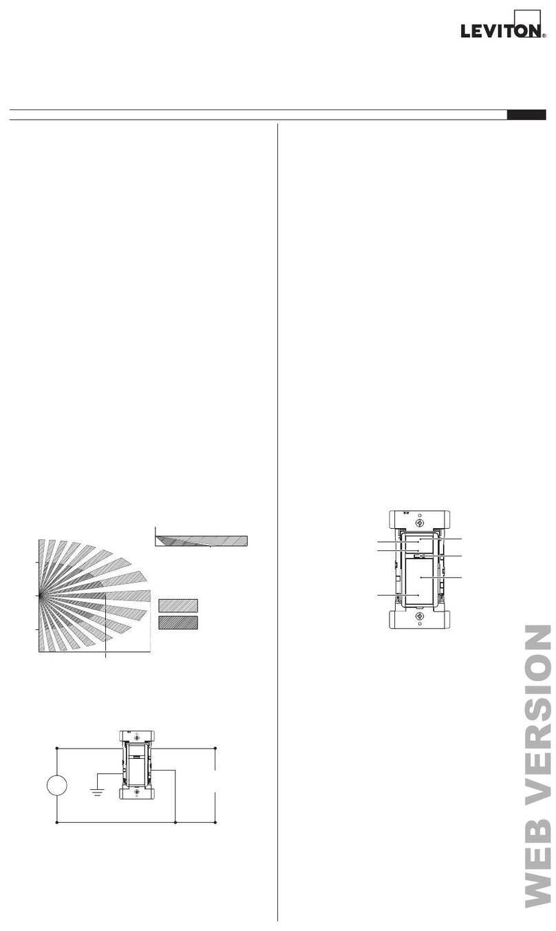
Perform the following steps for a more precise
Ambient Light adjustment (see Figure 4):
1. Make the adjustment when the actual ambient light
is at the level where no artificial light is required.
2. Turn the Ambient Light adjustment to the (-) position
(minimum light).
3. Turn the Time-Delay adjustment to the (-) position
(at 20 seconds) and leave the monitored space.
4. Re-enter the monitored space after the lights go
OFF and the lights will remain OFF.
5. Slowly turn the Ambient Light adjustment knob
towards (+) until the lights go ON.
6. Slightly turn the Ambient Light adjustment knob
back towards (-) and leave the monitored space.
7. When you return to the monitored space, the lights
should remain OFF. If the lights come ON, repeat
step 6 until the lights remain OFF when you re-
enter the monitored space, at the desired ambient
light level.
8. Reset the Time-Delay adjustment back to the
desired position.
TROUBLESHOOTING
• LIGHTS WILL NOT TURN ON
- Circuit breaker or fuse is OFF: Turn the breaker
ON. Ensure that lights being controlled are in working
order (i.e., working bulbs, integral switches ON, etc.).
- Sensor is wired incorrectly or may be
defective: Confirm that the sensor’s wiring is
done exactly as shown in the diagram and/or
inspect it visually for problems.
- Lens is dirty or obstructed: Inspect the lens
visually and clean if necessary, or remove the
obstruction.
• Ambient light setting is for a darker
background than that present: Adjust the
Ambient light setting.
• LIGHTS WILL NOT TURN OFF
- Sensor is wired incorrectly or may be
defective: Confirm that the sensor’s wiring is
done exactly as shown in the diagram and/or
inspect it visually for problems.
- Sensor may be mounted too closely to an air
conditioning or heating vent, or traffic in an
adjacent area is affecting sensor: Move the
sensor to another location, or close the vent.
- The line voltage has dropped: Perform the
necessary tests to ensure the line voltage has not
dropped beneath 100V (applicable to
ODC0S-I1,120VAC version only). If it has
dropped, check for operation of any large
appliances on the circuit, and turn them off.
- Light is being reflected from an object: Check
the area for any white or shiny surfaces that might
be reflective, and correct the situation.
• LIGHTS TURN OFF AND ON TOO QUICKLY
- Sensor may be mounted too closely to an air
conditioning or heating vent: Move the sensor
to another location, or close the vent.
- Light being reflected from an object: Check the
area for any white or shiny surfaces that might be
reflective, and correct the situation.
- Time delay set improperly: Adjust the TIME
DELAY (see SETTINGS section)
.
Hot (Black)
Neutral (White)
Sensor
Load
Black
White
Black
White
Blue
Blue
Line
120VAC, 60Hz
Hot (Black)
Neutral (White)
Load
Black
White
Red
White
Blue
Blue
Line
277VAC, 60Hz
Sensor
Wiring Diagram 2 - Cat. No. ODC0S-I7
Wiring Diagram 1 - Cat. No. ODC0S-I1
1M
3 FT
1
2 M
7 FT
2
3.7 M
13 FT
3
1M
3 FT
1
2 M
7 FT
2
3.7 M
13 FT
3
0
0
Figure 3A - Field-of-View (Horizontal)
26 Ft.
+
-
+
15 0
5
10
-
Time Light
Figure 4
Figure 3B - Field-of-View (Vertical)
DI-000-ODC0S-02B

This manual suits for next models

5

Other Leviton Security Sensor manuals

Leviton 47A00-2 User manual

Leviton

Leviton 47A00-2 User manual

Leviton DECORA ODS15-IDI Series User manual

Leviton

Leviton DECORA ODS15-IDI Series User manual

Leviton decora OSSMT-M3 User manual

Leviton

Leviton decora OSSMT-M3 User manual

Leviton CRS4K User manual

Leviton

Leviton CRS4K User manual

Leviton decora IPV05 User manual

Leviton

Leviton decora IPV05 User manual

Leviton decora IPV02 User manual

Leviton

Leviton decora IPV02 User manual

Leviton IPSD6 User manual

Leviton

Leviton IPSD6 User manual

Leviton DOS02 User manual

Leviton

Leviton DOS02 User manual

Leviton Intellect Solo Sensor ZLS05-ILW User manual

Leviton

Leviton Intellect Solo Sensor ZLS05-ILW User manual

Leviton 61A00-1 Mounting instructions

Leviton

Leviton 61A00-1 Mounting instructions

Leviton ODSMT-MD User manual

Leviton

Leviton ODSMT-MD User manual

Leviton GreenMAX OSR15-MCW User manual

Leviton

Leviton GreenMAX OSR15-MCW User manual

Leviton Provolt ODC10-UDW User manual

Leviton

Leviton Provolt ODC10-UDW User manual

Leviton decora ODS10-TD Series User manual

Leviton

Leviton decora ODS10-TD Series User manual

Leviton ZLS10-ILW User manual

Leviton

Leviton ZLS10-ILW User manual

Leviton ZLS10-IDW User manual

Leviton

Leviton ZLS10-IDW User manual

Leviton ODC15-IDW User manual

Leviton

Leviton ODC15-IDW User manual

Leviton HB011-PDX User manual

Leviton

Leviton HB011-PDX User manual

Popular Security Sensor manuals by other brands

Radiodetection RD8100 Operation manual

Radiodetection

Radiodetection RD8100 Operation manual

Honeywell SiXGB installation instructions

Honeywell

Honeywell SiXGB installation instructions

LEGRAND 0 672 26 manual

LEGRAND

LEGRAND 0 672 26 manual

BFT RIP installation manual

BFT

BFT RIP installation manual

Autronica AutroSense 75 Installation & Commissioning Handbook

Autronica

Autronica AutroSense 75 Installation & Commissioning Handbook

ELTEX ETM Solo Viewer manual

ELTEX

ELTEX ETM Solo Viewer manual

D+H VRS 10 Original instructions

D+H

D+H VRS 10 Original instructions

Vertiv GEIST RTAFHD3 Quick installation manual

Vertiv

Vertiv GEIST RTAFHD3 Quick installation manual

Afriso EURO-INDEX OWWG 3 operating instructions

Afriso EURO-INDEX

Afriso EURO-INDEX OWWG 3 operating instructions

lap 9695V instructions

lap

lap 9695V instructions

ion science PhoCheck TIGER quick start guide

ion science

ion science PhoCheck TIGER quick start guide

Metrotech 9800XT SFL2 Series Operation manual

Metrotech

Metrotech 9800XT SFL2 Series Operation manual

Pyle PRMDC40 user manual

Pyle

Pyle PRMDC40 user manual

DSC PG4914 installation instructions

DSC

DSC PG4914 installation instructions

Elitech CLD-100 instruction manual

Elitech

Elitech CLD-100 instruction manual

THORLABS PDB47 C Series Operation manual

THORLABS

THORLABS PDB47 C Series Operation manual

THORLABS INT-POL-1300 Operation manual

THORLABS

THORLABS INT-POL-1300 Operation manual

Monacor SMILE-16 operating instructions

Monacor

Monacor SMILE-16 operating instructions

manuals.online logo
manuals.online logoBrands
  • About & Mission
  • Contact us
  • Privacy Policy
  • Terms and Conditions

Copyright 2025 Manuals.Online. All Rights Reserved.