12
PM
Event
A
MTWThFSaSu
Offset
P
12
AM
Delete
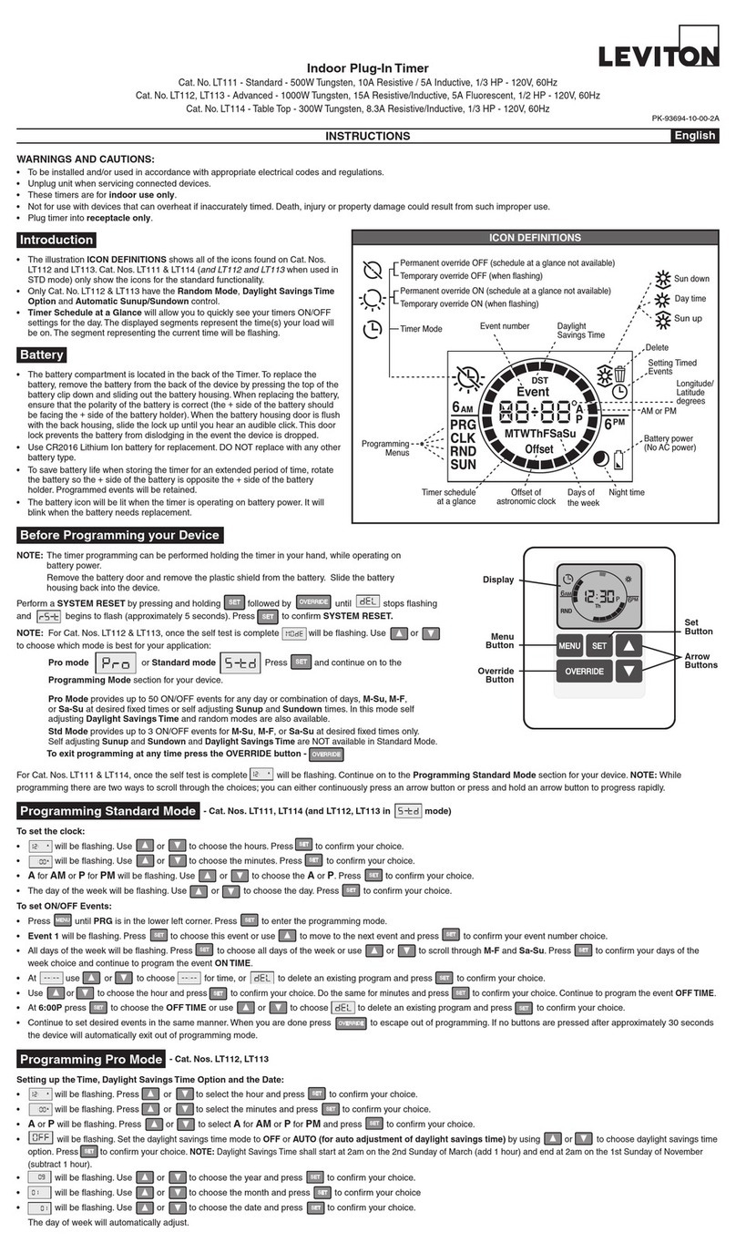
ICON DEFINITIONS
Setting Timed
Events
Day time
Sun down
Sun up
Night time
Timer Mode
DST
Daylight
Savings Time
Event number
AM or PM
Longitude/
Latitude
degrees
Battery power
(No AC power)
Programming Menus
Days of the week
Offset of
astronomic clock Timer schedule
at a glance
Permanent override OFF (schedule at a glance not available)
Temporary override OFF (when flashing)
Permanent override ON (schedule at a glance not available)
Temporary override OFF (when flashing)
LIMITED 5 YEAR WARRANTY AND EXCLUSIONS
LevitonwarrantstotheoriginalconsumerpurchaserandnotforthebenetofanyoneelsethatthisproductatthetimeofitssalebyLevitonisfreeofdefectsinmaterialsandworkmanshipundernormalandproperuseforveyearsfromthepurchasedate.Leviton’sonlyobligationistocorrectsuchdefectsbyrepairorreplacement,atitsoption,ifwithinsuchveyearperiodtheproductisreturnedprepaid,with
proofofpurchasedate,andadescriptionoftheproblemtoLeviton Manufacturing Co., Inc., Att: Quality Assurance Department, 201 North Service Road, Melville, NewYork 11747.Thiswarrantyexcludesandthereisdisclaimedliabilityforlaborforremovalofthisproductorreinstallation.Thiswarrantyisvoidifthisproductisinstalledimproperlyorinanimproperenvironment,overloaded,misused,opened,
abused,oralteredinanymanner,orisnotusedundernormaloperatingconditionsornotinaccordancewithanylabelsorinstructions.There are no other or implied warranties of any kind, including merchantability and fitness for a particular purpose,butifanyimpliedwarrantyisrequiredbytheapplicablejurisdiction,thedurationofanysuchimpliedwarranty,includingmerchantabilityandtnessfor
aparticularpurpose,islimitedtoveyears.Leviton is not liable for incidental, indirect, special, or consequential damages, including without limitation, damage to, or loss of use of, any equipment, lost sales or profits or delay or failure to perform this warranty obligation.Theremediesprovidedhereinaretheexclusiveremediesunderthiswarranty,whetherbasedoncontract,tortorotherwise.
DI-000-VPT24-02B©2010LevitonMfg.Co.,Inc.
PROGRAMMING GUIDE
12
PM
A
Th
MENU
SET
12
AM
Override button
Decide which mode is best for your application:
Pro mode or Standard mode
Pro Modeprovidesupto50ON/OFFeventsforanydayor
combinationofdays,M-Su, M-F, or Sa-Suatdesiredxedtimesor
selfadjustingSunup and Sundowntimes.Inthismodeselfadjusting
Daylight Savings Timeandrandommodesarealsoavailable.
Std Modeprovidesupto3ON/OFFeventsforM-Su, M-F, or Sa-Su
atdesiredxedtimesonly.SelfadjustingSunup and Sundown and
Daylight Savings TimeareNOTavailableinStandardMode.
To exit programming at any time press override button -
To set the clock:
• willbeashing.Useortochoosethehours.Press
toconrmyourchoice.
• Theminuteswillbeashing.Useortochoosetheminutes.
Presstoconrmyourchoice.
• AforAM or PforPMwillbeashing.Useortochoosethe
Aor P.Presstoconrmyourchoice.
• Thedayoftheweekwillbeashing.Useortochoosethe
day.Presstoconrmyourchoice.
SET
SET
SET
SET
A
To set ON/OFF Events:
• PressuntilPRGisinthelowerleftcorner.Presstoenterthe
programmingmode.
• Event 1willbeashing.Presstochoosethiseventoruse
tomovetothenexteventandpresstoconrmyoureventnumber
choice.
• Alldaysoftheweekwillbeashing.Presstochoosealldaysof
theweekoruseortoscrollthroughM-F and Sa-Su. Press
toconrmyourdaysoftheweekchoiceandcontinuetoprogram
the event ON TIME.
• Atuseortochoosefortime,orto
deleteanexistingprogramandpresstoconrmyourchoice.
• Useortochoosethehourandpresstoconrm
yourchoice.Dothesameforminutesandpresstoconrmyour
choice.ContinuetoprogramtheeventOFF TIME.
• At6:00PpresstochoosetheOFF TIME or use or to
choosetodeleteanexistingprogramandpresstoconrm
your choice.
• Continuetosetdesiredeventsinthesamemanner.Whenyouare
donepresstoescapeoutofprogramming.Ifnobuttonsare
pressedafterapproximately30secondsthedevicewillautomatically
exitoutofprogrammingmode.
SET
SET
SET
SET
SET
SET
SET
SET
SET
SET
MENU
PROGRAMMING STANDARD MODE
e)willbeashing.Useortochoosetheyearand
presstoconrmyourchoice.
f) willbeashing.Useortochoosethemonthand
presstoconrmyourchoice
g)willbeashing.Useortochoosethedate
andpresstoconrmyourchoice.Thedayofweekwill
automaticallyadjust.
SET
SET
SET
NOTE: DaylightSavingsTimeshallstartat2amonthesecond
SundayofMarch(addonehour)andendat2amontherstSunday
ofNovember(subtractonehour).
OPERATION • OnyourtimerpressuntilSUNappearsatthebottomofthe
screenandpresstoconrmyourchoice.
• Useortochooseyourlatitude(N)andpressto
conrmyourchoice.
• Useortochooseyourlongitude(W)andpressto
conrmyourchoice.
•
willbeashingtorepresenttheoffsettime.Choosethe
amountoftime,ifany,toturntheloadON/OFFbeforeorafter
Sunup and SundownbypressingtoaddtimetotheSunup/
SundowntimeandusetosubtracttimefromtheSunup/
Sundowntime.Presstoconrmyourchoice(upto3hours
and59minutes).
• willappear.Thetimezoneclosesttothecoordinatesyou
enteredwillash.Pressifthisiscorrect.Ifthisisnotcorrect
useortochooseyourtimezoneandpressto
conrmyourchoice.
SET
SET
SET
SET
SET
SET
MENU
2. Programming yourTimer Options:
a) Setting Sunup, Sundown, desired Offset Time and Time Zone:
Sunup and Sundownareautomaticallyadjustedusingthe
latitudeandlongitudecoordinatesofyourlocation.Toobtainthese
coordinates go to www.leviton.com/VPT24andclickonLongitude/
Latitude Coordinates Lookup...Typeinyourhomeaddressand
pressenter.Yourlatitude(N)andlongitude(W)coordinateswill
beshownonthescreen.Writedownonlythe2or3digitnumber.
Disregardanegativesymbol(–)ifitpreceedsthenumber.
DST DST
• Alldaysoftheweekwillbeashing.Presstochooseall
daysoftheweekoruseortoscrollthroughM-F, Sa-
Su,anysingledayorcombinationofdays.NOTE: To choose a
combinationofdayspressaftereachdayyouwantandthen
moveontothenextdaybypressingor.Continueto
scroll using until PRGashes.
SET
SET
• WhendonechoosingthedesireddaysPRGinthelowerleft
cornerwillash.Presstoconrmthechosendaysand
continue on to choosing the event TURN ON TIME.
SET
b) Setting ON/OFF Events:
• PressuntilPRGisinthelowerleftcorner.Pressto
entertheprogrammingmode.
• Event 1willbeashing.Presstochoosethiseventoruse
tomovetothenexteventandpresstoconrmyour
eventnumberchoice.
SET
SET
SET
MENU
12
PM
12
AM
Event
12
PM
12
AM
Event
MTWThFSaSu
12
PM
12
AM
Event
• Atuseortochoosefortime,for
Sundown
,for
Sunup
ortodeleteanexisting
programandpresstoconrmyourchoice.
• Ifischosen,useortochoosethehourand
presstoconrmyourchoice.Dothesameforminutes.
• At6:00PpresstochooseaTURN OFF TIME or use
ortochoosefor
Sundown
,for
Sunup
ortodeleteanexistingprogramandpresstoconrm
your choice.
• Ifischosen,useortochoosethehourand
presstoconrmyourchoice.Dothesameforminutes.
• Continuetosetdesiredeventsinthesamemanner.Whenthis
isdonepresstoescapeoutofprogramming.Ifnobuttons
arepressedafterapproximately30secondsthedevicewill
automaticallyexitoutofprogrammingmode.
SET
SET
SET
SET
SET
b)Pressandholdfollowedby (Override) until stops
ashingandashes(approximately5seconds).
PresstoconrmdeviceReset.
c)Productwillgothroughabriefselftestandthenwillbegin
toash.Choose or byusing or until the
selectedmodeappearsandpressingtoconrmyourchoice.
d)ContinuetotheprogrammingsectionfortheModechosen.
SET
SET
SET
1. Setting up the Time, Daylight Savings Time Option and the Date:
a) willbeashing.Press or to select the hour and
press toconrmyourchoice.
b) willbeashing.Press or toselecttheminutesand
press toconrmyourchoice.
c) Aor Pwillbeashing.PressortoselectAforAM or
PforPMandpresstoconrmyourchoice.
d)willbeashing.SetthedaylightsavingstimemodetoOFF
or AUTO (for automatic adjustment of daylight savings time)
byusingortochoosedaylightsavingstimeoptionand
presstoconrmyourchoice.
SET
SET
SET
SET
A
A
PROGRAMMING PRO MODE
lfatanytimeyouwanttodeleteallofyourprogrammedevents,youcan
performaDELETE ALL EVENTSfunction:
a)GentlylifttheVPT24doorfromthebottomofthepushpaduntilan
audibleclickisheard.
b)Pressandholdfollowedby(Override) until starts
ashing.
c)PresstoconrmDELETE ALL EVENTS.Alleventswillbe
deletedfromyourdeviceandtheTimer Schedule at a Glancewill
appearwithonlythecurrenttimesegmentashing.
SET
SET
CHANGING SETTINGS
DELETE ALL EVENTS
• PressuntilCLKappearsatthebottomofthescreen.Press
toenterthismode.Adjusttheclockusingorand
pressingaftereachsetting.
SET
MENU
SET
Turning Random Mode ON/OFF (Pro Mode ONLY):
Thisfunctionwilladdorsubtractanywherefrom1to20minutestoeach
selected ON and OFFtimetocreatearandompattern.
• PressuntilRNDappearsatthebottomofthescreenandpress
toenterthismode.
• Useortotogglebetweenandandpress
toconrmyourchoice.
SET
SET
MENU
Timer Schedule at a Glancewillallowyoutoquicklyseeyourtimers
ON/OFFsettingsfortheday.Thedisplayedsegmentsrepresentthe
time(s)yourloadwillbeon.Thesegmentrepresentingthecurrenttime
willbeashing.
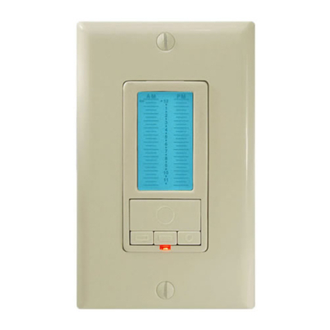
Backlit LCD displaywilllightupwhenanybuttonispressedandwill
extinguish30secondsafterthelastbuttonpress.
To program your device:
a)PerformaSystem ResetbygentlyliftingtheVPT24doorfromthe
bottomofthepushpaduntilanaudibleclickisheard.Thedoorwill
stayopenwhileyouareprogrammingthedevice:
TIME ZONE CALCULATIONS
Longitude
60° – 80°
81° – 95°
96° – 110°
111° – 135°
136°-143°
144°+
Time Zone
Eastern
Eastern, Central
Central, Mountain
Mountain, Pacific, Alaskan
Pacific, Alaskan, Hawaii-Aleutian
Alaskan, Hawaii-Aleutian
ThetimezonesarelimitedtotheNorthAmericanContinent.Theoptions
youarepresentedaredeterminedviayourlongitudeinthechartbelow:
For additional information, contact Leviton’s
Techline at 1-800-824-3005 or visit Leviton’s
website at www.leviton.com
CoveredbyoneormoreUS&Foreign
Patentsandpatentspending
AllRightsIncludingTradeDressRightsReserved
TROUBLESHOOTING
• Lightsickeringorintermittentpowertoload
-Loadhasabadconnection.
-Wiresnotsecuredrmlywithwireconnectorsoftimerswitchor
terminalscrewsofremote.
• LoaddoesnotturnONandLocatorLEDdoesnotturnON
- Circuitbreakerorfusehastripped.
-Loadisburnedout.
-LoadNeutralconnectionisnotwired.
• Remotedoesnotoperatelights
-Ensurethattotalwirelengthdoesnotexceed300ft(90m).
FCC COMPLIANCE STATEMENT
ThisdevicecomplieswithPart15oftheFCCRules.Operationis
subjecttofollowingtwoconditions:(1)thisdevicemaynotcause
harmfulinterference,and(2)thisdevicemustacceptanyinterference
received,includinginterferencethatmaycauseundesiredoperationof
the device.
Thisequipmenthasbeentestedandfoundtocomplywiththelimits
foraClassBDigitalDevice,pursuanttoPart15oftheFCCRules.
Theselimitsaredesignedtoprovidereasonableprotectionagainst
harmfulinterferenceinaresidentialinstallation.Thisequipment
generates,uses,andcanradiateradiofrequencyenergyand,ifnot
installedandusedinaccordancewiththeinstructions,maycause
harmfulinterferencetoradiocommunications.However,thereisno
guaranteethatinterferencewillnotoccurinaparticularinstallation.If
thisequipmentdoescauseharmfulinterferencetoradioortelevision
reception,whichcanbedeterminedbyturningtheequipmentOFFand
ON,theuserisencouragedtotrytocorrecttheinterferencebyoneor
moreofthefollowingmeasures:
• ReorientorrelocatethereceivingAntenna.
• Increasetheseparationbetweentheequipmentandthereceiver.
• Connecttheequipmentintoanoutletonacircuitdifferentfromthat
towhichthereceiverisconnected.
• Consultthedealeroranexperiencedradio/tvtechnicianforhelp.
FCC CAUTION
AnychangesormodicationsnotexpresslyapprovedbyLeviton
ManufacturingCo.,Inc.,couldvoidtheuser'sauthoritytooperatethe
equipment.
• Degreeofprotectionprovided:IPX0
• TypeofAction:1CS
Whenusingaremoteswitch(es)withyourvizia+TM24hourtimer
youwillbeabletoactivatethetemporaryoverrideorthepermanent
overridefromtheremoteswitch.Toactivateordeactivatethetemporary
overridepressthepushpadontheremoteswitch.Toactivate
permanentoverridepressandholdtheremoteswitchpushpad.Either
oftheseactionswilltogglethestateoftheload.
USE IN MULIT-LOCATION APPLICATIONS
• ActivateTemporaryOverridebypressingthepushpadtotogglethe
load (ON to OFF or OFF to ON).
• ActivatePermanentOverridebypressingandholdingthepushpad
forseveralsecondstomaintaintheloadinthecurrentstate(eitherON
or OFF).
TIMER OVERRIDES
