LIP-9048DSS - Quick Installation Guide 1LIP-9048DSS - Quick Installation Guide 2LIP-9048DSS - Quick Installation Guide 3
Installation
Your IP phone and DSS should be placed on a level surface near an electrical outlet, such as a
desk or table top.
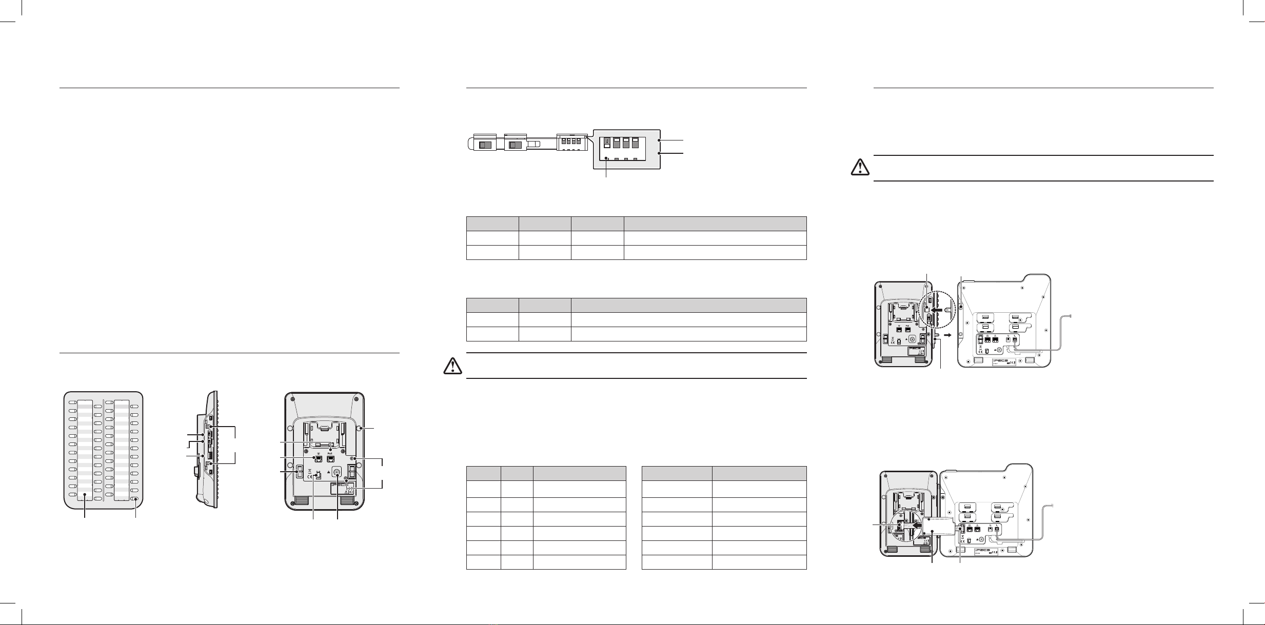
Connecting DSS with IP Phone
To install this DSS correctly, please follow the procedures below.
Caution! To avoid damaging equipment, remove the power from the IP phone before
connecting a DSS.
1. Set the power mode, protocol type, and PoE class in advance. See PoE Class Setting on page 2
for details.
2. Make sure that the Joint Bracket is aligned with the side of the DSS, and insert the one side of
the Joint Bracket into the mounting holes.
3. And insert the other side of the Joint Bracket into the mounting holes on the side of your phone.
4. Use the provided screws to connect the DSS and phone rmly together.
5. At the back of the DSS and phone, remove the rubber plug from the Accessory Expansion
Module(AEM) port.
6. Plug the 12-Pin cable into the AEM port on the the DSS and phone. (When installing additional
DSS, be sure to use a 12-pin cable to connect each DSS)
7. Place the Wire Protective Cover behind the DSS and align the screwholes with the Wire
Protective Cover screwholes on the DSS.
8. Tighten the screw to secure the Wire Protective Cover.
Settings
Set the LIP-9048 DSS for connection depending on the model of IP phone you are using. The
switches are hidden on the back of right side of the DSS. (Note that you need to remove the
plastic protective cover from the DSS to begin the necessary preparations.)
Power Mode
The MODE switch is used to choose the power mode between Slave and Master.
Symbol Mode Power Description
S Slave 5V LIP-9048DSS receives power from another DSS.
M Master 48V LIP-9048DSS provides power itself.
Protocol Type
The TYPE switch is used to choose a call protocol type between iPKTS and SIP.
Symbol Type Description
1 iPKTS Supports the IP Key Telephone System protocol (iPKTS)
2 SIP Supports the Session Initiation Protocol (SIP)
Caution! Set the DSS's protocol type to SIP, when connecting to LIP-9050/71 model (up to two
DSSs are connected to the phone). Power can be supplied only from the PoE.
PoE Class (IEEE802.3af standard)
The LIP-9048 DSS supports devices with PoE class 0, 1, 2, 3 and 4, this class indicates the power
range required for the device to work. The devices which classied as Class 0 to allow them
to draw all the power they may need without setting of the DIP switch. The DIP switch has 4
individual PIN, you can do the conguration for need adjustment. The default PINs position on
the Switch is'0000', which indicated the Class '0'.
Class PIN Power Ranges(W) Model Power Consumption(W)
0 0000 0.44W - 12.95W LIP-9048DSS 2.86W
1 1000 0.44W - 3.84W LIP-9020 3.05W
2 0100 3.84W - 6.49W LIP-9030 3.39W
3 0010 6.49W - 12.95W LIP-9040 3.34W
4 0001 12.95W - 25.5W LIP-9050 13W
LIP-9071 14.4W
Before Starting
About this guide
This document provides information about the LIP-9048DSS (Direct Station Select) module
installation for the LIP-9000 Series.
Package contents
The following items are included in your LIP-9048DSS package. Before installation, ensure that
you have the following package contents:
• LIP-9048DSS with Paper Labels and Multi-angle Stand
• Joint Bracket/Wire Protective Cover/Screws
• CAT5E Ethernet Cable
• 12 Pin Cable
• Quick Installation Guide
Description
The LIP-9048DSS provides 48 exible buttons that can be programmed to connect with an IP
phone. Accoring to the protocol type selection explains on page 2, you will set up the protocol
type of LIP-9048DSS. If you are setting a SIP type, you can connect up to two LIP-9048DSS (iPKTS
type up to four) to the phone. (except the LIP-9010).
Component names
This illustration outlines your LIP-9048DSS's basic layout.
1 2 3 4
0
1
CLASS
S M
MODE
1 2
TYPE
Direct Station Select
LIP-9048DSS
Made in Thailand
1 2 3 4
0
1
CLASS
S M
MODE
1 2
TYPE
Direct Station Select
LIP-9048DSS
Made in Thailand
1 2 3 4
0
1
CLASS
S M
MODE
1 2
TYPE
Direct Station Select
LIP-9048DSS
Made in Thailand
Paper Label
PoE Switch
AEM Port
RJ45 Jack
Connecting
Screwhole
Mounting
Holes
MODE Switch
TYPE Switch
Adapter Jack
User-dened
feature keys
PoE Jack
Wire Protective Cover
Screwholes
Hook
1 2 3 4
0
1
CLASS
S M
MODE
1 2
TYPE
1 2 3 4
0 OFF
1 ON
Ex) The DIP Switch PIN 1 is 'On' position.
Direct Station Select
LIP-9048DSS
Made in Thailand
Useonly with approved limited power source
LIP-9040
Mounting Hole
Direct Station Select
LIP-9048DSS
Made in Thailand
Useonly with approved limited power source
LIP-9040
Direct Station Select
LIP-9048DSS
Made in Thailand
AEM
Port
Connecting
Screwhole
12 Pin cableWire Protective Cover
Joint Bracket


