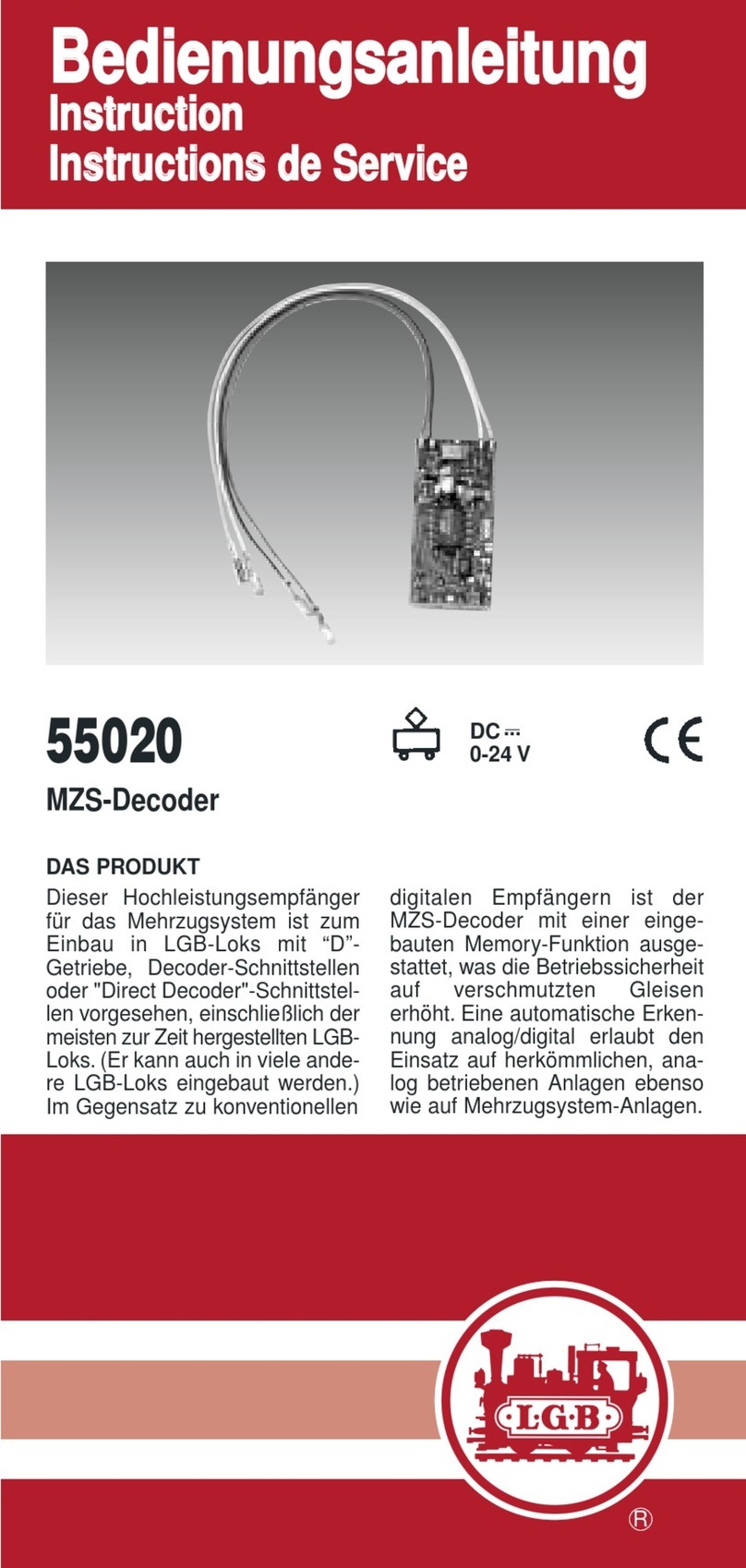
LGB 55021 User manual

MZS-Decoder
55021

2
GB
D
Einbau in Lokomotiven ohne Schnittstelle 5
Der nicht erweiterte Umbau (einfach) 5
Der erweiterte Umbau (für Profis) 5
Erster Betrieb 5
Einbau mit kabelgebundener Schnittstelle 6
Einbau in Loks mit Direct Decoder-Schnittstelle 6
Programmieren des Decoders 7
Erweiterte Programmierung 7
Programmieren mit dem Universal-Handy 55015 7
Einstellwerte für CV 29 9
Einstellwerte für CV 51 9
Installation in Locomotives without a Digital Interface 11
Simple Conversion 11
Advanced Conversions (for pros) 11
First Operation 11
Installation with a Tethered Digital Interface 12
Installation in Locomotives with a Direct Decoder Interface 12
Programming the Decoder 13
Advanced Programming 13
Programming with the 55015 Universal Hand Controller 13
Settings for CV 29 15
Settings for CV 51 15

3
NL
F
Installation dans des locomotives sans interface 17
Transformation standard (simple) 17
Transformation avancée (pour les pros) 17
Première exploitation 17
Installation avec interface reliée par câble. 18
Installation dans des locos avec interface décodeur Direct 18
Programmation du décodeur 19
Programmation avec le Universal-Handy 55015 19
Valeur de paramétrage pour CV 29 21
Valeurs de paramétrage pour CV 51 21
Montage in locomotieven zonder interface 23
De niet-geavanceerde ombouw (makkelijk) 23
De geavanceerde ombouw (voor profs) 23
Eerste bedrijf 23
Inbouw met interface met kabel 24
Montage in locs met direct-decoderinterface 24
De decoder programmeren 25
Geavanceerde programmatie 25
Programmeren met de Universal-Handy 55015 25
Instelwaarde voor CV 29 27
Instelwaarde voor CV 51 27
Montaje en locomotoras sin interfaz 29
La conversión no avanzada (sencilla) 29
La conversión avanzada (para profesionales) 29
Primera puesta en servicio 29
Montaje con interfaz cableada 30
Montaje en locomotoras con interfaz Direct Decoder 30
Programación del decoder 31
Programación avanzada 31
Programación con el móvil universal 55015 31
Valores de configuración de la CV 29 33
Valores de configuración de la CV 51 33
Installazione in locomotive senza interfaccia 35
L’installazione non estesa (facile) 35
L’installazione estesa (per esperti) 35
Primo funzionamento 35
Installazione con interfaccia collegata ai cavetti 36
Installazione in locomotive con interfaccia per Decoder Direct
36
Programmazione del Decoder 37
Programmazione estesa 37
Programmazione con il comando manuale
universale 55015 37
Einstellwerte für CV 29 39
Einstellwerte für CV 51 39

4
Dieser Decoder wird benötigt um Lokomotiven
(Leistungsbedarf bis 1,5 A) für das Mehrzugsystem zu
digitalisieren. Er ist vorgesehen für den Einbau in LGB-
Lokomotiven mit „D-Getriebe”, „Decoderschnittstelle”
oder „Direct Decoder Schnittstelle”. Dem entsprechen
die meisten LGB-Lokomotiven.
Der Decoder ist für geräuscharmen Betrieb konstruiert
und verfügt über eine automatische analog/digital-Er-
kennung. Lokomotiven mit Decodern können unverän-
dert auf herkömmlichen, analog betriebenen Anlagen
eingesetzt werden.
Mit dem Universal-Handy 55015 oder dem MZS-PC-
Decoder-Programmiermodul 55045 können Sie weitere
Funktionen des Decoders programmieren, z. B. Anfahr-
spannung, Beschleunigung und Bremsverzögerung.
Es gilt generell, dass pro Motor ein Decoder eingesetzt
wird. D.h., bei Lokomotiven mit 2 Motoren benötigen Sie
auch 2 Decoder. Mischen Sie nicht unterschiedliche
Decoder in einem Fahrzeug.
Installieren Sie nie die Decoder unter anliegender Span-
nung. Decoder müssen trocken, geschützt und isoliert
gegen andere Bauteile eingebaut werden.
Vor dem Einbau des Decoders ist sicherzustellen, dass
sich die Lok elektrisch und mechanisch in einwandfrei-
em Zustand befindet. Mängel oder Verschmutzungen
sind unbedingt vor dem Einbau zu beseitigen. Grundsätz-
lich sind die Angaben des Lokherstellers zu beachten.
Achten Sie darauf, dass sich beim Fahrbetrieb keine
Kurzschlüsse einstellen können.
Für Schäden durch nicht fachgerechte Arbeiten können
wir keine Garantie gewähren.
Der oder die Decoder müssen an einem trockenen und
geschützten Platz in der Lokomotive eingebaut werden.
Befestigen Sie den Decoder so, dass er sich bei der
Fahrt nicht lösen kann und nicht mit unisolierten Bautei-
len in Berührung kommen kann.

5
Einbau in Lokomotiven ohne Schnittstelle
Der Decoder wird mit den 4 farbigen Kabeln direkt am
Getriebe angeschlossen. Entfernen Sie die bestehenden
Anschlusskabel vom Getriebe und stecken Sie statt
derer die 4 Decoder-Kabel an. Beachten Sie die am
Getriebe aufgedruckten Farben (gn = grün; bn = braun;
ws = weiß; ge = gelb), die den Farben der Decoder-Kabel
entsprechen.
Der nicht erweiterte Umbau (einfach)
Nehmen Sie von der „alten” Elektronik den weißen und
den braunen Draht, stecken Sie diesen auf den Motor-
ausgang des Decoders. Den grünen und den gelben
Draht isolieren Sie gut. Damit ist der nicht erweiterte
Umbau fertig, und Ihre Lok verhält sich wie auf Ihrer
analogen Anlage, mit dem Unterschied, dass sie Digital
gesteuert werden kann.
Der erweiterte Umbau (für Profis)
Entfernen Sie die „alte” Elektronik aus der Lok mit allem
was dazu gehört (Lampen, Dampfentwickler, Motorre-
gelung). Nun müssen Sie die Lok neu verdrahten. Für
die Lampen müssen separat Leitungen zum Decoder
gezogen werden, wo Sie dann die Kabelenden an
den jeweiligen Ausgängen für Vorder- bzw. Rücklicht
anschliessen.
Erster Betrieb
Achten Sie vor dem Testen darauf, dass die Spannungen
der Funktionsausgänge (Auslieferung 24V) passend zu
den angeschlossenen Verbrauchern eingestellt sind.
Den Dampfentwickler legen Sie direkt auf den Funkti-
onsnsausgang. Auch hier gilt: achten Sie vor dem Testen
auf die richtige Spannung.
Sollte es eine Lok mit Sound sein, sollten Sie auf die
nicht erweiterte Version zugreifen.
Ist es eine Lok mit zwei Motoren, installieren Sie
einen zweiten Decoder auf das zweite Getriebe. Die
Funktionen müssen nicht mehr angeschlossen werden,
da Sie z.B. das Licht nicht zweimal zugleich einschalten
können. Die Decoder sollten untereinander verbunden
sein. Dafür verbinden Sie die Stifte der Gleisaufnahme
parallel (ws auf ws, bn auf bn) miteinander.
Bei einem Umbau dieser herkömmlichen Art müssen Sie
bitte die runden Mehrzwecksteckdosen und die Verbin-
dung zur Oberleitung entfernen.

6
Einbau mit kabelgebundener Schnittstelle
Öffnen Sie die Lokomotive und suchen Sie auf der vor-
handenen Elektronik nach der Schnittstelle.
Die Schnittstelle erkennen Sie an vier Stiften die mit
„ge”, „ws”, „bn” und „gn” markiert sind, nebenan ist
eine leere Stiftwanne in der das Decoderzusatzkabel
55026 eingesteckt wird. Dieses Kabel wird entsprechend
der Kabelfarben mit den unten markierten Anschlüssen
verbunden. Einen evtl. notwendigen zweiten Decoder
stecken sie auf die zweite Reihe der Stifte.
Wenn vorhanden, müssen im Anschluss die neben der
Schnittstelle befindlichen Micro-Schalter, sog. DIP-
Switches, alle von „On” nach „Off” gestellt werden.
Lok wieder zusammenbauen und in Betrieb nehmen.
Einbau in Loks mit Direct Decoder-Schnittstelle
Öffnen Sie die Lokomotive und suchen Sie auf der vor-
handenen Elektronik nach leeren Federhülsen. In diese
Hülsen kann der Decoder sozusagen „Face-to-Face”
aufgedrückt und eingesteckt werden. Wundern Sie sich
nicht, wenn nicht alle Stifte des Decoders in einer Hülse
aufgenommen werden; es sind immer nur die Hülsen
aufgelötet, die zum reibungslosen Betrieb der jeweiligen
Lokomotive notwendig sind. Die 4 Anschlussdrähte des
Decoders zwicken Sie vorher ab (nicht ablöten).
Wenn vorhanden, müssen im Anschluss die neben der
Schnittstelle befindlichen Micro-Schalter, sog. DIP-
Switches, alle von „On” nach „Off” gestellt werden.
Die Lok wieder zusammenbauen und in Betrieb nehmen.
bn
or
gn
gb
rt bl

7
Programmieren des Decoders
Zahlreiche Funktionen des Decoders können individuell
programmiert werden. Dazu werden Funktionswerte in
Registern (Configuration Variables - CVs) programmiert.
Sie können die Funktionswerte auch mit dem Universal-
Handy 55015 programmieren.
Mit allen Eingabegeräten können Sie die Adresse des
Decoders wählen und programmieren. Jedoch ist je
nach Bauart dess Eingabegerätes der Adressbereich
begrenzt. Bei der Lokmaus 55010 haben Sie die Adres-
sen 1 – 8. Bei dem Lok-Handy 55016 die Adressen 0 – 15.
Bei dem Universal-Handy 55015 haben Sie die Adressen
0 – 22.
Die Vorgehensweise zum Programmieren entnehmen
Sie bitte der Anleitung des jeweiligen Steuergerätes.
Erweiterte Programmierung
Die erweiterte Programmierung ist in den meisten Fällen
nicht notwendig und sollte von Anfängern nur sehr
vorsichtig begonnen werden. Diese erweiterte Program-
mierung kann nur mit dem 55015 Universalhandy oder
mit dem PC-Programmer 55045 vorgenommen werden.
Die Einstellmöglichkeiten finden Sie in den Tabellen ab
Seite 8.
Programmieren mit dem Universal-Handy 55015
Die CVs 1 – 5 können mit dem Universal-Handy direkt
programmiert werden. Alle weiteren CVs müssen über
die Vorwahl 6, dann folgt die Anwahl der CV, dann Pfeil-
taste rechts, dann die Vorwahl 5, dann folgt die Eingabe
des Wertes, dann die Pfeiltaste rechts, programmiert
werden.

8
CV Bezeichnung Bereich ab Werk
60 Nachregelfaktor *
1 = gering, 255 = stark 1 – 255 48
61 Nachregesgeschwindigkeit *
0 = schnell, 255 = sehr langsam 0 – 255
62 Nachregelstärke *
0 = keine, 255 = maximale 0 – 255
67 –
94 frei programmierbare
Fahrstufentabelle * 0 – 255
* die Werte sind optimal für den LGB-Motor eingest-
gelt. Änderungen sind nicht zu empfehlen.
CV Bezeichnung Bereich ab Werk
1 Adresse 0 – 22 3
2Anfahrspannung
0 = langsam, 255 = Höchstgeschw. 0 – 255 0
3 Beschleunigung 0 – 255 3
4 Verzögerung 0 – 255 3
5Nach Eingabe von CV6 Funktionswert
in dem zu prog. CV
5 max. Spannung für höchst. Fahrstufe 1 – 255 255
6 Registeradresse beim Programmieren 4
29 Anzahl der Fahrstufen, Fahrtrichtung,
Analog- und/oder Digitalbetrieb, Fahr-
stufentabelle, siehe extra Tabelle
49
Spannungswert für F1
32 = Lok mit Schnittstelle
26 = 19 V Lampen
5 = 5 V Lampen
1 – 32 32
50 Spannungswert für Lichtausgänge
vgl. CV 49 1 – 32 32
51 Tastenzuordnung für F1,
siehe extra Tabelle
52 Tastenzuordnung für Licht v.,
siehe extra Tabelle
53 Tastenzuordnung für Licht r.,
siehe extra Tabelle
54 Lastregelung
0 = aus, 2 = an 0, 2 2
55 Reset 55

9
Einstellwerte für CV 29
Wert Fahrst. Richt. Betrieb Farstufentab.
0 14 normal Dig. ab Werk
1 14 invers Dig. ab Werk
2 28 normal Dig. ab Werk
3 28 invers Dig. ab Werk
4 14 normal An. + Dig. ab Werk
5 14 invers An. + Dig. ab Werk
6 28 normal An. + Dig. ab Werk
7 28 invers An. + Dig. ab Werk
16 14 14 normal Dig.
17 14 14 invers Dig.
18 28 28 normal Dig.
19 28 28 invers Dig.
20 14 normal An. + Dig. frei prog.
21 14 invers An. + Dig. frei prog.
22 28 normal An. + Dig. frei prog.
23 28 invers An. + Dig. frei prog.
Einstellwerte für CV 51
Wert Schalten mit Bemerkung
0 Lichttaste 9
1 Taste 1 bei Tasten 2 – 8 wird der Befehl
entspr. oft geschaltet
9 Taste 1 Tasten 2 – 8 werden ignoriert
10 Taste 2
11 Taste 3
12 Taste 4
13 Taste 5
14 Taste 6
15 Taste 7
16 Taste 8
64 Lichttaste 9 nur bei Rückwärtsfahrt
65 Taste 1 nur bei Rückwärtsfahrt
128 Lichttaste 9 nur bei Vorwärtsfahrt
129 Taste 1 nur bei Vorwärtsfahrt

10
This decoder is required to convert locomotives (power
requirement up to 1.5 amps) to digital for the multi-train
system. It is designed for installation in LGB locomotives
with the „D gear drive“, a „decoder interface“, or with
the „Direct Decoder Interface“. Most LGB locomotives
correspond to these specifications.
The decoder is designed for low noise operation and has
automatic analog/digital recognition. Locomotives with
decoders can be used unchanged on conventional lay-
outs operated with analog. You can program additional
functions for the decoder with the 55015 Universal Hand
Controller or with the 55045 MTS PC Decoder Program-
ming Module, such as start-up voltage, acceleration,
and braking delay.
It is a general rule that one decoder is used per motor.
This means that you need 2 decoders for locomotives
with 2 motors. Do not mix different decoders in a single
locomotive or powered unit.
Never install decoders when there is voltage present.
Decoders must be dry, protected, and insulated from
other components when they are being installed.
You must be sure before installing the decoder that
the locomotive is in perfect electrical and mechanical
condition. Defects or dirt must absolutely be corrected
before installation. It is a fundamental rule that you must
adhere to the specifications of the locomotive manufac-
turer. Make sure that no short circuits can occur when
the locomotive is being run.
There is no warranty coverage for damages arising from
improper work.
The decoder(s) must be installed in the locomotive in a
dry, protected area. Mount the decoder so that it will not
come loose during operation and come into contact with
uninsulated components.

11
Installation in Locomotives without a Digital
Interface
The decoder is connected directly to the locomotive‘s
drive system by means of the 4 colored wires. Remove
the existing wires from the drive system and attach the 4
decoder wires. Pay attention to the colors printed on the
drive system (gn = green; bn = brown; ws = white;
ge = yellow) that correspond to the colors of the deco-
der wires.
Simple Conversion
Take the white and the brown wire from the „old“
electronic circuit and plug them into the motor outputs
on the decoder. Insulate the green and the yellow wire
well. This completes the simple conversion, and your
locomotive will behave in the same manner on your ana-
log layout with the difference that it can be controlled
digitally.
Advanced Conversions (for pros)
Remove the „old“ electronic circuit from the locomotive
and everything that goes with it (lights, smoke generator,
motor monitoring). Now, you must rewire the locomotive
Separate wires to the decoder must be put in for the
lights. The ends of these wires are then connected to
the appropriate outputs for the front and the rear lights.
First Operation
Before doing any testing, make sure that the voltage
supplied at the function outputs (24 volts) is appropriate
for the users connected to these outputs.
Connect the smoke generator directly to the function
output. This rule also applies here: Make sure the
voltage is appropriate for the smoke generator before
testing it.
If you have a locomotive with sound, you should use the
simple conversion.
If you have a locomotive with two motors, install a se-
cond decoder for the second drive system. The functions
do not have to be connected to the second decoder,
since you cannot turn the lights on twice at the same
time, for example. The decoders should be connected
together. To do this, connect the pins for track power in
parallel with each other (ws to ws, bn to bn).
When doing a usual conversion such as this, you must
remove the round general-purpose plugs and the con-
nection to the catenary.

12
Installation with a Tethered Digital Interface
Open the locomotive and look for the digital interface on
the existing electronic circuit board.
You will recognize the interface from the four pins
marked with „ge“, „ws“, „bn“, and „gn“; next to that is a
free pin receptacle in which the 55026 decoder auxiliary
cable is plugged. This cable goes to the connections
marked below according to the wire colors. Plug the
second decoder that may be necessary in the second
row of pins.
If present, the micro switches located next to the digital
interface, the so-called DIP switches, must all be set
from „On“ to „Off“.
Re-assemble the locomotive and put it back into ope-
ration.
Installation in Locomotives with a Direct Decoder
Interface
Open the locomotive and look for unoccupied spring
sleeves on the existing electronic circuit. The decoder
can be pressed and plugged into these sleeves so to
speak „face-to-face“. Do not be surprised if not all of
the pins on the decoder are accepted in a sleeve; only
those sleeves required for trouble-free operation of the
locomotive in question are soldered. Trim the 4 connec-
ting wires on the decoder in advance (do not unsolder
these wires).
If present, the micro switches located next to the digital
interface, the so-called DIP switches, must all be set
from „On“ to „Off“.
Re-assemble the locomotive and put it back into ope-
ration.
bn
or
gn
gb
rt bl

13
Programming the Decoder
Numerous functions on the decoder can be programmed
individually. To do this, function values are programmed
in registers (Configuration Variables - CVs). You can also
program the function values with the 55015 Universal
Hand Controller.
You can select and program the decoder‘s address with
all of the entry devices. However, the address range is
limited depending on the type of entry device. With the
55010 Locomotive Mouse, you have addresses 1 – 8.
With the 55016 Locomotive Hand Controller, addresses
0 – 15. With the 55015 Universal Hand Controller, you
have addresses 0 – 22.
The programming procedure can be found in the instruc-
tions for each of the control devices.
Advanced Programming
In most cases, advanced programming is not necessary
and should be done by beginners with extreme caution.
Advanced programming can only be done with the
55015 Universal Hand Controller or with the 55045 PC
Programmer.
Possible settings can be found in the tables starting on
Page 14.
Programming with the 55015 Universal Hand Controller
CVs 1 – 5 can be programmed directly with the Universal
Hand Controller. All other CVs must be programmed
using Code 6, then you select the CV, then the right
arrow button, then Code 5, then you enter the value, then
the right arrow button.

14
CV Description Range As set
at the
factory
60 Adjustment factor *
1 = slight, 255 = strong 1 – 255 48
61 Adjustment speed *
0 = fast, 255 = very slow 0 – 255
62 Adjustment strength *
0 = none, 255 = maximum 0 – 255
67 –
94 Freely programmable
Speed level table * 0 – 255
* The values are set to be optimal for LGB motors. We
recommend against making changes.
CV Description Range As set
at the
factory
1 Address 0 – 22 3
2Startup voltage
0 = slow, 255 = maximum speed 0 – 255 0
3 Acceleration 0 – 255 3
4 Delay 0 – 255 3
5After entry of CV6 function value in the
CV to be programmed
5 Max. voltage for the max. speed level 1 – 255 255
6 Register address when programming 4
29 Number of speed levels, direction,
analog and/or digital operation, speed
level table, see extra table
49
Voltage value for F1
32 = locomotive with interface
26 = 19 volt lights
5 = 5 volt lights
1 – 32 32
50 Voltage value for light outputs
compare CV 49 1 – 32 32
51 Button assignments for F1,
see extra table
52 Button assignments for front light(s),
see extra table
53 Button assignments for rear light(s),
see extra table
54 Load monitoring
0 = off, 2 = on 0, 2 2
55 Reset 55

15
Settings for CV 29
Value Speed
Level Direction Operation Speed Level
Table
0 14 normal digital as set at the
factory
1 14 reverse digital as set at the
factory
2 28 normal digital as set at the
factory
3 28 reverse digital as set at the
factory
4 14 normal analog +
digital as set at the
factory
5 14 reverse analog +
digital as set at the
factory
6 28 normal analog +
digital as set at the
factory
7 28 reverse analog +
digital as set at the
factory
16 14 14 normal digital
17 14 14 reverse digital
18 28 28 normal digital
19 28 28 reverse digital
20 14 normal analog +
digital freely prog.
21 14 reverse analog +
digital freely prog.
22 28 normal analog +
digital freely prog.
23 28 reverse analog +
digital freely prog.
Settings for CV 51
Value Control with Notes
0 Button 1
1 Button 1 With Buttons 2 – 8 the command
is often switched accordingly
9 Button 2 Buttons 2 – 8 are ignored
10 Button 3
11 Button 4
12 Button 5
13 Button 6
14 Button 7
15 Button 8
16 Light Button 9
64 Button 1 Only with locomotive in reverse
65 Light Button 9 Only with locomotive in reverse
128 Button 1 Only with locomotive in forward
129 Taste 1 Only with locomotive in forward

16
Ce décodeur sert à numériser les locomotives (intensité
requise jusqu’à 1,5 A) pour le système multitrain. Il est
prévu être installé dans des locomotives LGB avec „trans-
mission D“, „interface décodeur“ ou „interface décodeur
Direct“, c‘est à dire la plupart des locomotives LGB.
Le décodeur est conçu pour une exploitation silencieuse
et dispose d’un système de reconnaissance automa-
tique de mode analogique/mode numérique. Les loco-
motives équipées d’un décodeur peuvent être utilisées
telles quelles sur des réseaux traditionnels exploités en
mode analogique.
Le Universal-Handy 55015 ou le module de programma-
tion pour décodeur PC-SMT 55045 vous permet de pro-
grammer d’autres fonctions du décodeur, telles que la
tension de démarrage ou la temporisation d’accélération
et de freinage.
D‘une manière générale, il faut prévoir un décodeur
par moteur. Des locomotives équipées de deux moteurs
nécessiteront donc l’utilisation de deux décodeurs.
N’utilisez pas différents décodeurs dans un même
véhicule.
N’installez jamais les décodeurs dans un véhicule sous
tension. Les décodeurs doivent être installés au sec,
protégés et isolés des autres composants.
Avant l’installation du décodeur, vérifiez que l’état
électrique et mécanique de la locomotive est irréproch-
able. D’éventuels défauts ou saletés sont à éliminer im-
pérativement avant l’installation. De manière générale,
respectez les indications du fabricant de la locomotive.
Veillez à ce qu’aucun court-circuit ne puisse survenir
durant l’exploitation.
Toute détérioration causée par une utilisation non con-
forme ne saurait être prise en charge par la garantie.
L’emplacement du ou des décodeurs dans la locomotive
doit être sec et protégé. Fixez le décodeur de manière à
ce qu’il ne puisse pas se détacher durant la marche et
entrer en contact avec des composants non isolés.

17
Installation dans des locomotives sans interface
Le décodeur est directement relié au système de trans-
mission par 4 câbles de couleur. Débranchez les câbles
de raccordement existant du système de transmission et
remplacez les par les 4 câbles du décodeur. Respectez
les indications couleurs imprimées sur le système de
transmission (gn = vert ; bn = marron ; ws = blanc) qui
correspondent aux couleurs des câbles du décodeur.
Transformation standard (simple)
Prenez les fils blanc et marron de „l’ancien“ système
électronique et branchez-les sur la sortie moteur du
décodeur. Veillez à bien isoler les fils vert et jaune.
La transformation standard est terminée ; votre loco
se comporte comme sur un réseau analogique, à la
différence qu’elle peut aussi être commandée en mode
numérique.
Transformation avancée (pour les pros)
Retirez „l’ancien“ système électronique de la locomotive
avec tous les accessoires (lampes, générateur de fu-
mée, régulation moteur). Procédez au nouveau câblage
de la loco. Les lampes nécessitent vers le décodeur
l’installation de lignes distinctes dont les extrémités sont
reliées aux sorties correspondantes pour l’éclairage
frontal et les feux arrière.
Première exploitation
Avant de procéder à la marche test, veillez à ce que les
tensions des sorties fonction (24 V) soient adaptées aux
consommateurs raccordés.
Raccordez le générateur de fumée directement à la
sortie fonction. Là encore, veillez à ce que la tension soit
correcte avant de procédez au test.
S’il s’agit d‘une locomotive sonorisée, il est préférable
d’envisager la version standard.
S’il s’agit d’une locomotive équipée de deux moteurs,
installez un second décodeur sur le second système de
transmission. Les fonctions n‘ont plus besoin d‘être rac-
cordées étant donné que vous ne pouvez par exemple
pas allumer la lumière deux fois simultanément. Il est
préférable de relier les décodeurs entre eux. A cet effet,
reliez les ergots de la voie en parallèle (blanc sur blanc
et marron sur marron)
Pour une transformation de ce type, veillez à retirer
les prises multiples rondes ainsi que la liaison à la
caténaire.

18
Installation avec interface reliée par câble.
Ouvrez la locomotive et repérez l‘interface sur le sys-
tème électronique existant.
Vous la reconnaîtrez aux quatre ergots marqués „ge“,
„ws“, „bn“ et „gn“ ; à côté se trouve une embase mâle
libre dans laquelle doit être enfiché le câble supplé-
mentaire du décodeur 55026. Ce câble doit être relié
aux connexions marquées en bas conformément aux
couleurs indiquées. Le second décodeur éventuel doit
être branché sur la seconde rangée d’ergots.
Le cas échéant, les micro-commutateurs situés à côté
de l’interface, „commutateurs DIP“, doivent être positi-
onnés sur „Off“.
Refermez la loco et lancez l’exploitation.
Installation dans des locos avec interface dé-
codeur Direct
Ouvrez la locomotive et repérez les douilles élastiques
libres sur le système électronique existant. Ces douilles
permettent d’enficher le décodeur pour ainsi dire
„Face-to-face“. Ne vous étonnez pas s‘il est impossible
d’enficher tous les plots du décodeur dans une seule
douille ; seules les douilles nécessaires à l’exploitation
fiable de la locomotive concernée sont soudées. A
préalable, veillez à pincer les 4 fils de connexion du
décodeur (ne pas dessouder).
Le cas échéant, les micro-commutateurs situés à côté
de l’interface, „commutateurs DIP“, doivent être positi-
onnés sur „Off“.
Refermez la loco et lancez l’exploitation.
bn
or
gn
gb
rt bl

19
Programmation du décodeur
De nombreuses fonctions du décodeur peuvent être
programmées individuellement. A cet effet, les valeurs
de fonction sont programmées dans des registres
(variables de configuration - CVs). Vous pouvez égale-
ment programmer ces valeurs avec l’appareil portable
Universal-Handy 55015.
Toutes les unités d‘entrée permettent de sélectionner
et de programmer l’adresse du décodeur. Toutefois, le
domaine d’adresse est limité en fonction du type d’unité
d’entrée. Sur la locosouris 55010, vous disposez des ad-
resses 1 à 8 ; sur le loco-handy 55016, des adresses 0 à
15 et sur le Universal-Handy 55015, des adresses 0 à 22.
Pour la programmation, veuillez suivre les instruc-
tions figurant sur la notice de l’appareil de commande
concerné.
Programmation avancée
Dans la plupart des cas, la programmation avancée
n’est pas nécessaire et doit être envisagée par les débu-
tants avec prudence. Cette programmation avancée est
réalisable uniquement avec le Universalhandy 55015 ou
avec le programmateur PC 55045.
Vous trouverez les possibilités de paramétrage possibles
dans les tableaux à partir de la page 20.
Programmation avec le Universal-Handy 55015
Les CV de 1 à 5 peuvent être programmées directement
avec le Universal-Handy. Toutes les autres CVs doivent
être programmées de la manière suivante : préfixe 6,
sélection de la CV, touche flèche droite, préfixe 5, saisie
de la valeur, touche flèche droite.

20
CV Désignation Domaine Départ
usine
60 Facteur d’ajustement *
1 = faible, 255 = fort 1 – 255 48
61 Vitesse d’ajustement *
0 = rapide, 255 = très lente 0 – 255
62 Nachregelstärke *
0 = keine, 255 = maximale 0 – 255
67 –
94 frei programmierbare
Fahrstufentabelle * 0 – 255
* Les valeurs définies sont optimales pour le moteur
LGB. Toute modification est déconseillée.
CV Désignation Domaine Départ
usine
1 Adresse 0 – 22 3
2 Tension de démarrage 0 – 255 0
3 0 = marche lente, 255 = vitesse max. 0 – 255 3
4 Accélération 0 – 255 3
5 Temporisation
5Après entrée de la CV6, valeur à
programmer dans la CV 1 – 255 255
6Adresse de registration pour la
programmation 4
29
Nombre de crans de marche, sens
de marche, exploitation anal. et/ou
numér., tableau des crans de marche,
voir tableau suppl.
49
Valeur tension pour F1
32 = loco avec interface
26 = 19 V lampes
5 = 5 V lampes
1 – 32 32
50 Valeur tension pour sorties éclair.
cf CV 49 1 – 32 32
51 Affectation des touches pour F1,
voir tableau suppl.
52 Affectation des touches éclair. frontal,
voir tableau suppl.
53 Affectation des touches feux arrières,
voir tableau suppl.
54 Compensation de la charge
0 = désactivée, 2 = activée 0, 2 2
55 Réinitialisation 55
Table of contents
Languages:
Other LGB Media Converter manuals
Popular Media Converter manuals by other brands

Cross Technologies
Cross Technologies 2415-02 Series instruction manual

Tektronix
Tektronix 7D12 Service instructions manual

Texas Instruments
Texas Instruments ADS1274 manual

XtendLan
XtendLan XL-ADH11A quick start guide

Channel Vision
Channel Vision A0302 instructions

Matrix Audio
Matrix Audio X-sabre user manual

Teleste
Teleste EASI INE101 user manual

Cypress
Cypress CP-268S Operation manual

OT Systems
OT Systems FT210DB Series Installation and operation manual

Phoenix Contact
Phoenix Contact QUINT4-PS/12-24DC/24DC/1.3/PT manual

Extron electronics
Extron electronics TSC 100 user manual

Moxa Technologies
Moxa Technologies Media Converter user guide