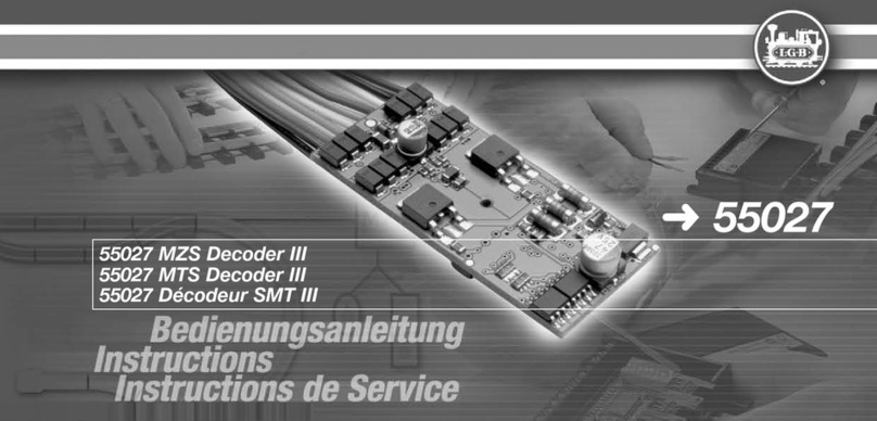
LGB 55027 User manual

2
Mit diesem Decoder lassen sich LGB-Lokomotiven mit
„DCC-Schnittstellen“ für den Einsatz mit dem LGB-Mehr-
zugsystem umrüsten („digitalisieren“). Der Decoder kann
auch für andere Modelle verwendet werden. Dank seiner
Ausgangsleistung von 3 Ampere wird auch für zweimotorige
Lokomotiven nur ein Decoder benötigt.
Achtung! Dieser Decoder ist nicht zum Einbau in LGB-Loko-
motiven mit Schnittstellen für den Decoder LGB 55020/55021
vorgesehen. Hier empfehlen wir nach wie vor den MZS-Lok-
Decoder II (LGB 55021).
Ausstattung:
• Lok-Decoder für Digitalbetrieb (LGB MZS, NMRA-DCC)
und Analogbetrieb (Gleichspannung)
• 2 Lichtausgänge (vorne, hinten)
• 6 Funktionsausgänge
• Lastnachregelung analog und digital
• Überlast- und Temperaturschutz
• Programmierbare Funktionen
• Anschlusskabel für LGB-DCC-Schnittstelle
Achtung! Installieren Sie nie einen Decoder unter anlie-
gender Spannung. Der Decoder muss trocken und geschützt
eingebaut werden. Befestigen Sie den Decoder sicher und
dauerhaft, um Kurzschlüsse zu vermeiden.
With this decoder, you can retrot LGB locomotives with
“DCC interfaces“ for use with the LGB Multi-Train System.
The decoder also can be used for other models. Because
of its output of 3 amps, even two-motor locomotives require
only a single decoder.
Attention! This decoder is not intended for installation in
LGB locomotives with interfaces for LGB 55020/LGB 55021
decoders. For these installations, we recommend the LGB
55021 MTS Loco Decoder II.
Features:
• loco decoder for digital (LGB MTS, NMRA DCC) and
analog operation (DC)
• 2 lighting terminals (front, rear)
• 6 function terminals
• Back-EMF analog and digital
• protection against overload and overheating
• programmable functions
• connecting cable for LGB DCC interface
Attention! Never install a decoder when the loco is con-
nected to a powered track or power source. The decoder
must be mounted in a dry and protected location. Attach the
decoder securely, so that it cannot loosen and cause short
circuits.

3
Inhaltsverzeichnis: Seite
Einbau bei Loks mit LGB + DCC-Schnittstelle 4
Einbau in andere Loks 4
Programmieren der Funktionswerte 4
Table of Contents: Page
Installation in locos with LGB “DCC interface” 6
Installation in other locomotives 6
Programming functions 6
Sommaire : Page
Montage sur les locomotives à interface LGB-DCC 8
Montage dans d‘autres locomotives 8
Programmation des valeurs de fonction 8
Ce décodeur permet de convertir les locomotives LGB à
«interface DCC» (de les «numériser») pour pouvoir les
intégrer dans un système multitrain LGB. Le décodeur peut
aussi être utilisé pour d‘autres modèles. Grâce à sa puis-
sance de sortie de 3 Ampères, pour les locomotives à deux
moteurs aussi un seul décodeur est nécessaire.
Attention ! Ce décodeur n‘est pas prévu pour être monté
dans les locomotives LGB possédant des interfaces pour le
décodeur LGB 55020/55021. Dans ce cas aussi, nous recom-
mandons le décodeur de locomotive SMT II (LGB 55021).
Équipement :
• Décodeur de locomotive pour fonctionnement numérique
(LGB SMT, NMRA-DCC) et analogique (tension continue)
• 2 sorties éclairage (avant, arrière)
• 6 sorties de fonction
• Réajustage analogique et numérique de la charge
• Protection thermique et contre la surcharge
• Fonctions programmables
• Câble de connexion pour l‘interface LGB-DCC
Attention ! N‘installez jamais un décodeur sous tension.
Le décodeur doit être sec et être monté de manière à être
protégé. Fixez le décodeur correctement et de manière
permanente pour éviter tout court-circuit.

4
Bild 1 Einbau bei Loks mit LGB-DCC-Schnittstelle
Fig. 1 Installation in locos with LGB “DCC interface“
Img. 1 Montage sur les locomotives à interface LGB-DCC
SND
F2
F1
Sound 65xxx
Decoder GND
F1
F2
6,5 V
Decoder +
F2
Licht hinten / rear light
Motor -
Gleix / Track -
Gleis / Track +
Motor +
Licht vorne / front light
Decoder GND
Decoder +
Decoder + ist der gemeinsame Anschluss für Licht
und F1 – F6
Decoder + is the common connection for lights and
auxiliary functions F1 – F6
Décodeur + est la connexion commune pour éclairage
et F1 à F6

5
Bild 2 Einbau in andere Loks
Fig. 2 Installation in other locomotives
Img. 2 Montage dans d‘autres locomotives
F1
F2
backlight / Licht hinten
Motor -
track / Gleis -
track / Gleis +
F3
F4
F5
F6
Decoder +
Decoder -
Motor +
frontlight / Licht vorne
Decoder -
Decoder +

6
Technische Daten:
• Abmessungen: 55 x 25 mm
• Spannungsversorgung: 0-24 Volt DC oder DCC
• Motorausgang: max. 3 A
• Lichtausgänge: max. je 0,3 A
• Funktionsausgänge: max. je 0,8 A (max. 1,3 A in Summe
aller Licht- und Funktionsausgänge)
Einbau bei Loks mit LGB-DCC-Schnittstelle
• Lok öffnen, um an die Hauptplatine zu gelangen.
• DCC-Schnittstelle (Abb. 1) auf der Platine nden.
• Auf der Decoderschnittstelle bendet sich eine Brücke.
• Brücke abziehen und statt dessen das Kabel des Deco-
ders anschließen.
Hinweise:
• Der Stecker am Decoderkabel passt nur in einer Ausrich-
tung auf die Stifte der Platine.
• Falls der Decoder ausgebaut wird, muss die Brücke wie-
der auf die DCC-Schnittstelle aufgesteckt werden. Sonst
funktioniert die Lok nicht.
• Wenn ein Decoder in die Lok eingebaut ist, ist der Be-
triebsartenschalter funktionslos.
Einbau in andere Loks
Der Decoder kann auch zum Einbau in andere Lokomotiven
verwendet werden. Entfernen Sie den Stecker am Kabel
und schließen Sie den Decoder entsprechend Abb. 2 an. Für
erweiterte Einbauten müssen Kabel an die Lötstellen auf der
Decoderplatine angelötet werden. Dabei darf der Decoder
nicht zu stark erhitzt werden.
Hinweise:
• Wir empfehlen, den Decoder in der LGB-Service-Abtei-
lung ein bauen zu lassen. Weitere Informationen erhalten
Sie bei Ihrem LGB-Fachhändler oder direkt beim Märklin
Reparatur Service
• Achtung! Das Loch in der Mitte der Platine darf nicht zum
Befestigen einer Schraube verwendet werden.
Programmieren der Funktionswerte
Zahlreiche Funktionen des Decoder können individuell
programmiert werden. Dazu werden Funktionswerte in Regi-
stern (Conguration Variables - CVs) mit einem PC über das
MZS-PC-Decoderprogrammier-Modul 55045 programmiert.
Sie können die Funktionswerte auch mit dem Universal-
Handy 55015 programmieren.
Hinweise:
• Es ist nicht notwendig, die Funktionswerte zu ändern
(außer CV 1 Lokadresse), doch lässt sich über einige
Programmierungen das Fahrverhalten Ihrer Lokomotive
verbessern und genau Ihren Wünschen anpassen.
• Bei Fehlprogrammierungen kann über Register CV 7
der Auslieferungszustand der wichtigsten Register des
Decoders wieder hergestellt werden.

7
CV Beschreibung Bereich Bemerkung
1 Lokadresse (Standard kurz) 1 – 127 (3) Nur wenn CV 29, Bit 5 = 0
2 Anfahrspannung 1 – 255 (2)
3 Beschleunigungswert 1 – 255 (3)
4Verzögerungswert 1 – 255 (3)
5Max. Fahrgeschwindigkeit 1 – 255
(255)
6 Mittlere Fahrgeschwindigkeit 1 – 255 (64)
5 + 6 Bei Programmierung mit älteren
Universal-Handys 55015:
CV 6 = zu programmierende CV-Nr.
CV 5 = Funktionswert
7Reset 55 = Grundwerte
66 = Motorwerte
77 = Funktionswerte
9 Motorfrequenz 0 – 3 (0) 16 / 2 / 0.4 / 0.06 kHz
13 Funktion F-Ausgänge analog 0 – 63 (3)
17 Lange Lokadresse 128 – 10239
(128) Wenn CV 29, Bit 5 = 32
18 Lange Lokadresse
29 NMRA Kongurations-Register (4) Bit 0 = Fahrtrichtung (0/1)
Bit 1 = Anzahl der Fahrstufen (14/28) (0/2)
Bit 2 = Betriebsart (digital / analog+digital (0/4)
Bit 5 = kurze / lange Adresse (0/32)
49 Lastnachregelung / Funktionsauslö-
sung und andere Funktionen (7) Bit 0 = Funktionsauslösung parallel/seriell (0/1)
Bit 1 = digitale Lastnachregelung (0/2)
Bit 2 = analoge Lastnachregelung (0/4)

8
CV Beschreibung Bereich Bemerkung
50 Licht: Spannungswert 1 – 32 (32) Hier können Sie die Spannung für die Lichtausgänge
einstellen (für 5V-Birnen 5 einstellen).
51 Licht (vorne): Schaltbefehlszuordnung (128) 0 = Schalten mit Lichttaste,
1 - 16 = Schalten mit entsprechender Funktionstaste
x + 64 = nur bei Rückwärtsfahrt an
x + 128 = nur bei Vorwärtsfahrt an
52 Licht (hinten): Schaltbefehlszuordnung (64) siehe CV 51
53 Spannungswerte für F1 und F2 (32) 1 – 32
x + 64 = Nur die Spannung des Ausgangs F1 wird einge-
stellt (volle Gleisspannung am anderen Ausgang).
x + 128 = Nur die Spannung des Ausgangs F2 wird einge-
stellt (volle Gleisspannung am anderen Ausgang).
54 Funktionszuordnung F1 (1) siehe CV 51
55 Sonderfunktionen für F1 (0) 0 = Dauerbetrieb
1 – 15 = symmetrisches Blinken (Zeitbasis 0,25 sec)
x + 16 = Wechselblinken von F1 und F2
x + 64 = Impulsfunktion z.B. für Entkuppler
x + 128 bzw + 192 = asymmetrisches Blinken
56 Funktionszuordnung F2 (2) siehe CV 51
57 Sonderfunktionen für F2 (0) siehe CV 55
58 Pausenzeit bei Halt mit
Richtungswechsel 0 – 255 (0) nur für Analogbetrieb
0,5 sec mal Funktionswert
59 Funktionszuordnung Rangiergang 1 – 16 (8) = Nummer der Funktionstaste
60 Lastregelung: max. Nachregelstärke 1 – 15 (2) Großer Wert = starke Nachregelung
61 Lastregelung: Regelgeschwindigkeit 1 – 255 (60) Großer Wert = langsame Nachregelung

9
CV Beschreibung Bereich Bemerkung
62 Lastregelung: Begrenzung der max.
Nachregelung 1 – 255
(255) 255 = keine Begrenzung
67 – 94 Frei programmierbare Fahrstufenkurve 1 – 255 Die Geschwindigkeitstabelle wird immer mit 28 Werten
abgelegt, die in CV 67 bis CV 94 programmiert werden.
Beim Betrieb mit 14 Fahrstufen wird jeder zweite Wert
übersprungen.
Grundwerte der programmierbaren Tabelle:
6, 8, 10, 13, 16, 19, 22, 26, 31, 36, 42, 48, 54, 60, 68, 76, 84, 92,
102, 112, 124, 136, 152, 168, 188, 208, 228, 232
112 Spannungswerte für F3 und F4 (32) siehe CV 53
113 Funktionszuordnung F3 (3) siehe CV 51
114 Sonderfunktionen für F3 (0) siehe CV 55
115 Funktionszuordnung F4 (4) siehe CV 51
116 Sonderfunktionen für F4 (0) siehe CV 55
117 Funktionszuordnung F5 (5) siehe CV 51
118 Sonderfunktionen für F5 (66) siehe CV 55
119 Funktionszuordnung F6 (6) siehe CV 51
120 Sonderfunktionen für F6 (8) 0 = Dauerbetrieb
1 – 15 = Zeitbasis für Soundtakterzeugung (Takt für Dreh-
zahlsimulation)
Bei Bit-Programmierungen werden die Werte (x) der einzel-
nen Bits addiert und das Ergebnis als Funktionswert für das
betreffende CV programmiert.

10
Installation in other locomotives
The decoder can be installed in other locomotives. Remove
the plug on the decoder cable and connect the decoder as
shown in Fig. 2. For advanced installations, wires have to be
soldered to the decoder. Make sure you do not overheat the
decoder when soldering.
Hints:
• We recommend decoder installation by an LGB service
station. For more information, contact your authorized
LGB retailer or Märklin Reparatur Service.
• Attention! The hole in the middle of the circuit board must
not be used to attach the decoder.
Programming functions
You can program numerous functions of the onboard deco-
der to suit your requirements. Program the “function values”
in “registers” (CVs) using a PC and the LGB 55045 MTS PC
Decoder Programming Module. You can also program the
function values using a LGB 55015 Universal Remote.
Hints:
• It is not necessary to change the function values (except
loco address). However, changing a few CVs can improve
the running characteristics of your locomotive and adapt
it to your requirements.
• If programming results in unsatisfactory operation, you
can reset CV 7 to reprogram the factory pre-set values of
most important CVs.
Specifications:
• dimensions: 55 x 25 mm
• input voltage: 0-24 volt DC or DCC
• motor terminal: max. 3 amp
• lighting terminals: max 0.3 amp each
• function terminals: max. 0.8 amp each (max. 1,3 amp for
the sum of all lighting and function terminals).
Installation in locos with LGB “DCC interface“
• Disassemble the loco to access the main circuit board.
• Find the “DCC interface“ (Fig. 1) on the main circuit
board.
• Remove the plug on the decoder interface.
• Plug the decoder cable onto the decoder interface.
Hints:
• The plug of the decoder ts only in one direction onto the
pins on the loco circuit board.
• If the decoder is removed, the original plug must be
replaced on the DCC interface. Otherwise, the loco will
not work.
• The power control switch does not work when a decoder
is installed.

11
CV Description Range Notes
1 Locomotive address (Standard short) 1 – 127 (3) Only when CV 29, Bit 5 = 0
2 Start up voltage 1 – 255 (2)
3 Acceleration value 1 – 255 (3)
4 Delay value 1 – 255 (3)
5Max. speed 1 – 255
(255)
6 Mittlere Fahrgeschwindigkeit 1 – 255 (64)
5 + 6 When programming with older 55015
universal hand controller:
CV 6 = CV number to be programmed.
CV 5 = function value
7Reset 55 = Basic values
66 = Motor values
77 = Function values
9 Motor frequency 0 – 3 (0) 16 / 2 / 0.4 / 0.06 kHz
13 Function F analog outputs 0 – 63 (3)
17 Long locomotive address 128 – 10239
(128) When CV 29, Bit 5 = 32
18 Long locomotive address
29 NMRA conguration register (4) Bit 0 = Direction of travel/(0/1)
Bit 1 = Number of speed levels (14/28) (0/2)
Bit 2 = Mode of operation (digital / analog+digital) (0/4)
Bit 5 = short / long address (0/32)
49 Load readjustment / function activation
and other functions (7) Bit 0 = Function activation parallel/serial (0/1)
Bit 1 = Digital load readjustment (0/2)
Bit 2 = Analog load readjustment (0/4)
50 Lights: voltage value 1 – 32 (32) Here you can set the voltage for the light outputs.

12
CV Description Range Notes
51 Lights (front): switching command
assignment (128) 0 = Switch with light button,
1 – 16 = Switch with corresponding function button
x + 64 = on only in backwards direction of travel
x + 128 = on only in forwards direction of travel
52 Lights (rear): switching command
assignment (64) See CV 51
53 Voltage values for F1 and F2 (32) 1 – 32
x + 64 = Only the voltage for Output F1 is set (full track
voltage at the other output).
x + 128 = Only the voltage for Output F2 is set (full track
voltage at the other output).
54 Function assignment for F1 (1) See CV 51
55 Special functions for F1 (0) 0 = Continuous operation
1 – 15 = symmetrical blinking (base 0.25 sec)
x + 16 = Alternative blinking of F1 and F2
x + 64 = Impulse function, ex. for uncoupler
x + 128 or + 192 = asymmetrical blinking
56 Function assignment for F2 (2) See CV 51
57 Special functions for F2 (0) See CV 55
58 Idle time at a stop with a change of
direction 0 – 255 (0) Only for analog operation
0.5 seconds times the function value
59 Function assignment for switching
range 1 – 16 (8) = Number of the function button
60 Load monitoring: max. degree of load
readjustment 1 – 15 (2) Large value = high degree of load readjustment
61 Load monitoring: control speed 1 – 255 (60) Large value = slow load readjustment

13
CV Description Range Notes
62 Load monitoring: limitation on the max.
degree of load readjustment 1 – 255
(255) 255 = no limitation
67 – 94 Freely programmable speed level
curve 1 – 255 The speed table is always stored with 28 values that are
programmed in CV 67 to CV 94. When operating with 14
speed levels, every second value is skipped.
Basic values for the programmable table:
6, 8, 10, 13, 16, 19, 22, 26, 31, 36, 42, 48, 54, 60, 68, 76, 84, 92,
102, 112, 124, 136, 152, 168, 188, 208, 228, 232
112 Voltage values for F3 and F4 (32) See CV 53
113 Function assignment for F3 (3) See CV 51
114 Special functions for F3 (0) See CV 55
115 Function assignment for F4 (4) See CV 51
116 Special functions for F4 (0) See CV 55
117 Function assignment for F5 (5) See CV 51
118 Special functions for F5 (66) See CV 55
119 Function assignment for F6 (6) See CV 51
120 Special functions for F6 (8) 0 = Constant (normal function)
1 – 15 = Timing for sound cam simulator (rpm simulation)
For bit programming, add the individual values (x) for each
bit and program the result as the function value in the
respective CV.

14
Montage dans d‘autres locomotives
Le décodeur peut aussi être monté dans d‘autres locomo-
tives. Ôtez le connecteur de sur le câble et raccordez le
décodeur selon la Img. 2. Pour procéder à des montages
supplémentaires, les câbles doivent être brasés aux points
de brasage sur la carte-mère du décodeur. Le décodeur ne
doit pas être soumis à une chaleur trop importante.
Remarques :
• Nous recommandons de faire monter le décodeur par le
service de maintenance LGB. Vous obtiendrez de plus
amples informations auprès de votre revendeur LGB ou
directement auprès de LGB.
• Attention ! Le trou au milieu de la carte-mère ne doit pas
être utilisé pour xer une vis.
Programmation des valeurs de fonction
Un grand nombre de fonctions du décodeur peuvent être
programmées individuellement. C‘est la raison pour laquelle
les valeurs de fonction sont programmées dans des regis-
tres (Conguration Variables – CV) avec un PC au moyen du
module de programmation de décodeur SMT-PC 55045. Vous
pouvez également programmer les valeurs de fonction avec
la télécommande universelle 55015.
Remarques :
• Il n‘est pas nécessaire de changer les valeurs de fonction
(excepté l‘adresse locale CV 1), mais le comportement
de votre locomotive peut être amélioré et exactement
adapté à vos désirs grâce à quelques programmations.
• En cas de programmation erronée, le registre CV 7 per-
met de restaurer l‘état à la livraison des registres les plus
importants du décodeur.
Caractéristiques techniques :
• Dimensions : 55 x 25 mm
• Alimentation en tension : 0 à 24 V DC ou DCC
• Sortie moteur : max. 3 A
• Sorties éclairage : max. 0,3 A chacune
• Sorties de fonction : max. 0,8 A chacune (max. 1,3 A au
total de toutes les sorties d‘éclairage et de fonction).
Montage sur les locomotives à interface LGB-DCC
• Ouvrir la locomotive pour accéder à la carte-mère.
• Trouver l‘interface DCC (Img. 1) sur la carte-mère.
• Un pont se trouve sur l‘interface du décodeur.
• Retirer le pont et connecter le câble du décodeur à sa
place.
Remarques :
• Le connecteur du câble du décodeur ne peut se cher
que dans une direction sur les broche de la carte-mère.
• Si le décodeur doit être démonté, le pont doit de nouveau
être enché sur l‘interface DCC. La locomotive ne peut
sinon pas fonctionner.
• Le sélecteur de mode n‘a aucune fonction quand un
décodeur est monté dans la locomotive.

15
CV Description Domaine Remarque
1 Adresse de la locomotive (courte) 1 à 127 (3) Uniquement si CV 29, Bit 5 = 0
2Tension de démarrage 1 à 255 (2)
3Valeur d’accélération 1 à 255 (3)
4Valeur de temporisation 1 à 255 (3)
5Vitesse maximale 1 à 255
(255)
6 Vitesse moyenne 1 à 255 (64)
5 + 6 Pour la programmation avec
d’anciennes télécommandes univer-
selles (Universal-Handys) réf. 55015 :
CV 6 = N° de CV à programmer.
CV 5 = valeur de fonction
7Réinitialisation 55 = valeurs de base
66 = valeurs moteur
77 = valeurs de fonction
9 Fréquence moteur 0 à 3 (0) 16 / 2 / 0.4 / 0.06 kHz
13 Fonction Sorties F analogique 0 à 63 (3)
17 Adresse loco longue 128 à 10239
(128) Si CV 29, Bit 5 = 32
18 Adresse loco longue
29 Registre de conguration NMRA (4) Bit 0 = sens de marche /(0/1)
Bit 1 = nombre de crans de marche (14/28) (0/2)
Bit 2 = mode d’exploitation (numérique /
analogique+numérique) (0/4)
Bit 5 = adresse courte / longue (0/32)

16
CV Description Domaine Remarque
49 Compensation de la charge / Dé-
clenchement des fonctions et autres
fonctions
(7) Bit 0 = déclenchement des fonctions parallèle/série (0/1)
Bit 1 = compensation numérique de la charge /(0/2)
Bit 2 = compensation analogique de la charge /(0/4)
50 Eclairage : tension 1 à 32 (32) Vous pouvez ici dénir la tension pour les sorties
d’éclairage
51 Eclairage (avant) : Affectation des
ordres de commutation (128) 0 = commutation via touche éclairage,
1 - 16 = commutation avec touches de fonction correspondantes
x + 64 = activé uniquement en marche arrière
x + 128 = activé uniquement en marche avant
52 Eclairage (arrière)
Affectation des ordres de commutation
(64) voir CV 51
53 Tension pour F1 et F2 (32) 1 – 32
x + 64 = seule la tension de la sortie F1 est dénie (pleine
tension de voie à l’autre sortie).
x + 128 = seule la tension de la sortie F2 est dénie (pleine
tension de voie à l’autre sortie).
54 Affectation de la fonction F1 (1) voir CV 51
55 Fonctions spéciales pour F1 (0) 0 = exploitation permanente
1 – 15 = clignotement symétrique (base 0,25 sec.)
x + 16 = clignotement alternatif de F1 et F2
x + 64 = fonction d’impulsion, par ex. pour dételeur
x + 128 resp. + 192 = clignotement asymétrique
56 Affectation de la fonction F2 (2) voir CV 51
57 Fonctions spéciales pour F2 (0) voir CV 55
58 Temps de pause pour arrêt avec
inversion du sens de marche 0 à 255 (0) Uniquement pour exploitation analogique
0,5 sec fois valeur de la fonction

17
CV Description Domaine Remarque
59 Affectation de la fonction vitesse de
manœuvre 1 à 16 (8) = numéro de la touche de fonction
60 Régulation de la charge : force de
réajustage maximale 1 à 15 (2) Valeur élevée = compensation puissante
61 Régulation de la charge : vitesse du
réajustage 1 à 255 (60) Valeur élevée = compensation lente
62 Régulation de la charge : limitation du
réajustage maximal 1 à 255
(255) 255 = aucune limitation
67 – 94 Programmation libre de la courbe des
crans de marche 1 à 255 Le tableau des vitesses comprend toujours 28 valeurs
programmées dans CV 67 à CV 94. Dans le cas d’une
exploitation avec 14 crans de marche, une valeur sur deux
est ignorée.
Valeurs de base du tableau programmable :
6, 8, 10, 13, 16, 19, 22, 26, 31, 36, 42, 48, 54, 60, 68, 76, 84, 92,
102, 112, 124, 136, 152, 168, 188, 208, 228, 232
112 Tension pour F3 et F4 (32) voir CV 53
113 Affectation de la fonction F3 (3) voir CV 51
114 Fonctions spéciales pour F3 (0) voir CV 55
115 Affectation de la fonction F4 (4) voir CV 51
116 Fonctions spéciales pour F4 (0) voir CV 55
117 Affectation de la fonction F5 (5) voir CV 51
118 Fonctions spéciales pour F5 (66) voir CV 55
119 Affectation de la fonction F6 (6) voir CV 51
120 Fonctions spéciales pour F6 (8) 0 = Fonctionnement permanent de la sortie
1 – 15 = Base de temps pour la génération d‘impulsions de
son (cadence pour la simulation du régime)
En cas de programmation de bits, les valeurs des différents bits (x) doivent être additionnées et le résultat programmé comme
valeur de fonction pour le CV concerné.

18

19

130162/1112/Sm3Ef
Änderungen vorbehalten
© Gebr. Märklin & Cie. GmbH
Gebr. Märklin & Cie. GmbH
Stuttgarter Straße 55 - 57
73033 Göppingen
Deutschland
www.lgb.de
This device complies with Part 15 of the FCC Rules.
Operation is subject to the following two conditions:
(1) This device may not cause harmful interference, and
(2) this device must accept any interference received, including
interference that may cause undesired operation.
www.maerklin.com/en/imprint.html
Other manuals for 55027
1
This manual suits for next models
1
Table of contents
Languages:
Other LGB Media Converter manuals