LGB RuBB Dampfl ok 99 4652 User manual

Modell der RüBB Dampflok 99 4652
24267

2

3
Inhaltsverzeichnis: Seite
Sicherheitshinweise 4
Wichtige Hinweise 4
Funktionen 4
Betriebshinweise 4
Multiprotokollbetrieb 4
Wartung und Instandhaltung 6
Schaltbare Funktionen 7
CV -Tabelle 8
Bilder 40
Tabelle Funktionsmapping 42
Ersatzteile 44
Table of Contents: Page
Safety Notes 10
Important Notes 10
Functions 10
Information about operation 10
Multi-Protocol Operation 10
Service and maintenance 12
Controllable Functions 13
Table for CV 14
Figures 40
Table for Function Mapping 42
Spare parts 44
Inhoudsopgave: Pagina
Veiligheidsvoorschriften 22
Belangrijke aanwijzing 22
Functies 22
Bedrijfsaanwijzingen 22
Multiprotocolbedrijf 22
Onderhoud en handhaving 24
Schakelbare functies 25
CV 26
Afbeeldingen 40
Tabel functiemapping 42
Onderdelen 44
Indice del contenuto: Pagina
Avvertenze per la sicurezza 34
Avvertenze importanti 34
Funzioni 34
Avvertenze per ilfunzionamento 34
Esercizio multi-protocollo 34
Manutenzione ed assistere 36
Funzioni commutabili 37
CV 38
Figures 40
Tabella di mappatura delle Funzioni 42
Pezzi di ricambio 44
Sommaire : Page
Remarques importantes sur la sécurité 16
Information importante 16
Fonctionnement 16
Remarques sur l’exploitation 16
Mode multiprotocole 16
Entretien et maintien 18
Fonctions commutables 19
CV 20
Images 40
Tableau pour mapping des fonctions 42
Pièces de rechange 44
Indice de contenido: Página
Aviso de seguridad 28
Notas importantes 28
Funciones 28
Instrucciones de uso 28
Funcionamiento multiprotocolo 28
El mantenimiento 30
Funciones posibles 21
CV 32
Figuras 40
Tabla de mapeado de funciones 42
Recambios 44

4
Sicherheitshinweise
• DasModelldarfnurmiteinemdafürbestimmten
Betriebssystem eingesetzt werden.
• NurSchaltnetzteileundTransformatorenverwenden,
die Ihrer örtlichen Netzspannung entsprechen.
• DasModelldarfnurauseinerLeistungsquelleversorgtwerden.
• BeachtenSieunbedingtdieSicherheitshinweiseinderBedienungsanleitungzu
Ihrem Betriebssystem.
• NichtfürKinderunter15Jahren.
• ACHTUNG!FunktionsbedingtescharfeKantenundSpitzen.
Wichtige Hinweise
• DieBedienungsanleitungistBestandteildesProduktesundmussdeshalbaufbe-
wahrt sowie bei Weitergabe des Produktes mitgegeben werden.
• FürReparaturenoderErsatzteilewendenSiesichbitteanIhrenLGB-Fachhändler.
• Entsorgung:www.maerklin.com/en/imprint.html
Funktionen
• DasModellistfürdenBetriebaufLGB-Zweileiter-Gleichstrom-Systemenmit
herkömmlichenLGB-Gleichstrom-Fahrpultenvorgesehen(DC,0-24V).
• WerkseitigeingebauterMultiprotokoll-Decoder(DC,DCC,mfx).
• ZumEinsatzmitdemLGB-Mehrzugsystem(DCC)istdasModellaufLokadresse03
programmiert.ImBetriebmitmfxwirddieLokautomatischerkannt.
• Mfx-TechnologiefürMobileStation/CentralStation.
NameabWerk:99 4652
• VeränderbareLautstärkederGeräusche.
Vorbereitung
KuppelnSiedieLokandenTender:
• SteckenSiedasVerbindungskabelderLokindieSteckdoseamTenderunddas
KabeldesTendersindieLok.Kabelnichtverwechseln!
• HängenSiedenKupplungshakenderLokindenBügelamTenderein.
Betriebsartenschalter
Das Modell hat einen vierstufigen Betriebsarten-Schalter im Tender unter dem
rechtenWasserdeckel(Bild1).
Pos.0 Lokstromlosabgestellt
Pos.1 Lokmotoren,SoundundBeleuchtungsindeingeschaltet
Pos. 2 & 3 wie Pos. 1
Elektronischer Sound
DasModellhateinenLautstärke-ReglerimTenderunterdemlinkenWasserdeckel
(Abb.2).DiePfeifeunddieGlockekönnenauchmitdembeiliegendenLGB-Sound-
Schaltmagneten(17050)ausgelöstwerden.DerSchaltmagnetlässtsichzwischendie
SchwellendermeistenLGB-Gleiseklipsen.DerMagnetbendetsichseitlichversetzt
unterdemeingeprägtenLGB-Logo.PlatzierenSiedenMagnetenmitdemLogoauf
derrechtenSeitedesGleises,umdiePfeifeauszulösen,wenndieLokdieseStelle
überquert.BeiAnordnungaufderanderenSeiteertöntdieGlocke.
Multiprotokollbetrieb
Analogbetrieb
DerDecoderkannauchaufanalogenAnlagenoderGleisabschnittenbetriebenwer-
den.DerDecodererkenntdieanalogeGleichspannung(DC)automatischundpasst
sichderanalogenGleisspannungan.EssindalleFunktionen,dieuntermfxoderDCC
fürdenAnalogbetriebeingestelltwurdenaktiv(sieheDigitalbetrieb).
Digitalbetrieb
Der Decoder ist ein Multiprotokolldecoder. Der Decoder kann unter folgenden Digital-
Protokolleneingesetztwerden:mfxoderDCC.
Das Digital-Protokoll mit den meisten Möglichkeiten ist das höchstwertige Digital-
Protokoll.DieReihenfolgederDigital-ProtokolleistinderWertungfallend:
Priorität1:mfx;Priorität2:DCC;Priorität3:DC
Hinweis: Digital-Protokolle können sich gegenseitig beeinflussen. Für einen stö-
rungsfreienBetriebempfehlenwir,nichtbenötigteDigital-ProtokollemitCongut-
ationsVariable(CV)50zudeaktivieren.DeaktivierenSie,soferndiesIhreZentrale
unterstützt,auchdortdienichtbenötigtenDigital-Protokolle.
WerdenzweiodermehrereDigital-ProtokolleamGleiserkannt,übernimmtderDe-
coderautomatischdashöchstwertigeDigital-Protokoll,z.B.mfx/DCC,somitwirddas
mfx-Digital-Protokoll vom Decoder übernommen.
Hinweis:BeachtenSie,dassnichtalleFunktioneninallenDigital-Protokollenmöglich
sind.UntermfxundDCCkönneneinigeEinstellungenvonFunktionen,welcheim
Analog-Betriebwirksamseinsollen,vorgenommenwerden.

5
Hinweise zum Digitalbetrieb
• DiegenaueVorgehensweisezumEinstellenderdiversenCVsentnehmenSiebitte
derBedienungsanleitungIhrerMehrzug-Zentrale.
• DieabWerkeingestelltenWertesindfürmfx/DCCgewählt,sodasseinbestmög-
lichstesFahrverhaltengewährleistetist.FürandereBetriebssystememüssen
gegebenenfallsAnpassungengetätigtwerden.
• DerBetriebmitgegenpoligerGleichspannungimBremsabschnittistmitder
werkseitigenEinstellungnichtmöglich.IstdieseEigenschaftgewünscht,somuss
aufdenkonventionellenGleichstrombetriebverzichtetwerden(CV29/Bit2=0).
mfx-Protokoll
Adressierung
• KeineAdresseerforderlich,jederDecodererhälteineeinmaligeundeindeutige
Kennung(UID).
• DerDecodermeldetsichaneinerCentralStationoderMobileStationmitseiner
UID automatisch an.
Programmierung
• DieEigenschaftenkönnenüberdiegrascheOberächederCentralStationbzw.
teilweise auch mit der Mobile Station programmiert werden.
• EskönnenalleCVmehrfachgelesenundprogrammiertwerden.
• DieProgrammierungkannentwederaufdemHaupt-oderdemProgrammiergleis
erfolgen.
• DieDefaulteinstellungen(Werkseinstellungen)könnenwiederhergestelltwerden.
• Funktionsmapping:FunktionenkönnenmitHilfederCentralStation60212(einge-
schränkt)undmitderCentralStation60213/60214/60215beliebigenFunktionstasten
zugeordnetwerden(SieheHilfeinderCentralStation).
DCC-Protokoll
Adressierung
• KurzeAdresse–LangeAdresse–Traktionsadresse
• Adressbereich:
1-127kurzeAdresse,Traktionsadresse
1 - 10239 lange Adresse
• JedeAdresseistmanuellprogrammierbar.
• KurzeoderlangeAdressewirdüberdieCV29ausgewählt.
• EineangewandteTraktionsadressedeaktiviertdieStandard-Adresse.
Programmierung
• DieEigenschaftenkönnenüberdieCongurationVariablen(CV)mehrfachgeän-
dert werden.
• DieCV-NummerunddieCV-Wertewerdendirekteingegeben.
• DieCVskönnenmehrfachgelesenundprogrammiertwerden(Programmierung
aufdemProgrammiergleis).
• DieCVskönnenbeliebigprogrammiertwerden(Programmierungaufdem
HauptgleisPoM).PoMistnurbeideninderCV-TabellegekennzeichnetenCV
möglich.DieProgrammierungaufdemHauptgleis(PoM)mussvonIhrerZentrale
unterstütztwerden(sieheBedienungsanleitungihresGerätes).
• DieDefaulteinstellungen(Werkseinstellungen)könnenwiederhergestelltwerden.
• 14bzw.28/128Fahrstufeneinstellbar.
• AlleFunktionenkönnenentsprechenddemFunktionsmappinggeschaltetwerden.
• WeitereInformation,sieheCV-TabelleDCC-Protokoll.
Eswirdempfohlen,dieProgrammierungengrundsätzlichaufdemProgrammiergleis
vorzunehmen.

6
Wartung
Schmierung
DieAchslagerunddieLagerdesGestängeshinundwiedermitjeeinemTropfen
Märklin-Öl(7149)ölen.
Austauschen der Glühlampen (E130023)
Lampen (vorne, hinten oben):LampengehäusevomModellabziehen.Eingesteckte
GlühlampeausdemSockelziehen.NeueGlühlampeeinstecken.Modellwieder
zusammenbauen.
Lampen (hinten unten):DenRingaußenamLampenglasentfernen.Vorsichtigdas
GlasvonderLaternehebeln.MiteinerPinzettedieeingesteckteGlühlampeausder
Fassungziehen.NeueGlühlampeeinsetzen.Modellwiederzusammenbauen.
Innenbeleuchtung:GlühlampemiteinerPinzetteausderFassungziehen.Neue
Glühlampeeinstecken.
Austauschen des Haftreifens (E126174)
- GestängehalterungzwischendererstenundzweitenAchseentfernen.
- Sechskantschraubenlösen,mitdenendieTreibstangenunddieKuppelstangenan
der dritten Achse befestigt sind.
- AufderUnterseitedesGetriebesbendensichmehrereSchrauben:Zweiteund
fünfte Schraube von vorne herausdrehen.
- GetriebeausdemRahmenziehen.Kabelabziehen.
- MiteinemkleinenachenSchraubenzieherdenHaftreifenauswechseln:
- AltenHaftreifenausderRille(Nut)imTreibradhebeln.
- NeuenHaftreifenvorsichtigindieRille(Nut)imRadschieben.
- Überprüfen,dassderHaftreifenrichtigsitzt.
- Modell wieder zusammenbauen.
Funktionsmapping
Esistmöglich,dieFunktionalitäten,dievomDedodergesteuertwerden,denFunkti-
onstastennachWunschzuzuordnen(mappen).DazumussinderentsprechendenCV
ein entsprechender Wert eingetragen werden.
InderTabelleaufdenSeiten42/43sinddieCVs(Zeilen)unddieFunktionalitäten
(Spalten)aufgeführt.ZujederTastegehören4CVs.AusPlatzgründenwurdenabCV
282(TasteF5)die4CVszujederTastejeweilsineinerZeilezusammengefasst.
Grundsätzlichistesmöglich,einerTastemehrereFunktionalitäten,bzw.eineFunkto-
nalitätmehrerenTastenzuzuweisen.
Hinweis: Die Programmierung des Funktionsmappings sollte nur durch erfahrene
Anwender durchgeführt werden.
JenachAuslegungdesDecoderskönneneinzelneFunktionalitätenüberSUSI
gesteuertsein.DieseFunktionalitätenwerdenvomDecoderalsSoundbehandelt.Die
zugehörigenLautstärkenkönnendannnichtverändertwerden.
Beispiele zum Funktionsmapping:
AUX2sollvorwärtsundrückwärtsaufFunktion3
CV272&CV372=8
CV273&CV373=0
CV274&CV374=0
CV275&CV375=0
Sound15sollvonvorwärtsundrückwärtsFunktion3aufFunktion8verlegtwerden.
Die bestehende Belegung von Funkton 8 wird dabei überschrieben.
CV275&CV375=0
CV273&CV373=0
CV274&CV374=0
CV275&CV375=0
CV297&CV397=0
CV298&CV398=0
CV299&CV399=0
CV300&CV400=4
hin zu Funktion 8
weg von Funktion 3
vorwärts
rückwärts

7
Programmieren der CV mit dem Universal-Handy 55015
DerinIhrerLokomotiveeingebauteDecoderisteineWeiterentwicklungderbishe-
rigenLGB-Decoder-Technologie.DementsprechendstehenweitmehrFunktionali-
tätenzurVerfügungalsbisherüblich.
UmdieseFunktionalitätenandiepersönlichenBedürfnisseanpassenzukönnen,sind
gegenüber bisherigen Decodern jedoch auch mehr Einstellmöglichkeiten notwendig.
Diese Einstellungen können auch mit dem Universal-Handy 55015 vorgenommen
werden. Da das Universal-Handy jedoch noch nicht für diese Decoder vorgesehen
war,istdasrichtigeVorgehenhieretwasumständlicher.
Grundsätzlichistzwischen3verschiedenenProgrammiermethodenzuunterschei-
den:
• ProgrammierenüberRegister(bisCV5)
• ProgrammierenüberCV(bisCV255)
• ProgrammierenüberPages(bisCV1024)
DieeinzelnenProgrammierabläufesindimFolgendenbeschrieben.Voraussetzung
istjeweils,dassdasProgrammiermoduleingestecktistunddieLokomotivemitdem
DecoderaufdementsprechendenGleissteht.
Programmieren über Register
BeimProgrammierenüberRegisterkönnendieCV1–5programmiertwerden.
• wenndasProgrammiermoduleingestecktwird,zeigtdasHandy
--
• gebenSiediegewünschteCVzweistelligein,z.B.„02“
• dasHandyzeigt
d -
• gebenSiejetztdengewünschtenWerteinundbestätigenSiemiteinemDruckauf
die Pfeiltaste
• dasHandyzeigtwieder
--
DieProgrammierungistabgeschlossen,dergewünschteWertwurdeindenDecoder
programmiert.
Programmieren über CV
DieProgrammierungüberRegisterlässtnurVeränderungenandenCVs1–5zu.Um
höhereCVszuprogrammieren,isteineandereMethodenotwendig.DasProgrammie-
renüberCVerlaubtVeränderungenandenCVs1–255.
Schaltbare Funktionen
Beleuchtung * LV+LR
+AUX1
Geräusch:Lokpfeifelang 1 Sound 1
Geräusch:Bremsenquietschenaus 2 BS
Geräusch:Glocke 3 Sound 3
Geräusch:Bahnhofsansage 4 Sound 4
Geräusch:Kohleschaufeln 5 Sound 9
Geräusch:Betriebsgeräusch* 6 FS
Rauchgenerator * 7 Sound7+
Sound 16
Geräuschelektronikaus/ein 8 Sound 14
ABV,aus 9
Führerstandsbeleuchtung 10 AUX 3
Rangiergang & Rangierlicht doppel A 11 LV+LR
+AUX1
Geräusch:Lokpfeifekurz 12 Sound 2
Geräusch:Injektor 13 Sound 12
Geräusch:Sanden 14 Sound 15
Geräusch:Luftpumpe 15 Sound 11
* im Analogbetrieb aktiv
Allgemeiner Hinweis zur Vermeidung elektromagnetischer Störungen:
UmdenbestimmungsgemäßenBetriebzugewährleisten,isteinpermanenter,ein-
wandfreierRad-Schiene-KontaktderFahrzeugeerforderlich.
FührenSiekeineVeränderungenanstromführendenTeilendurch.

8
Register Belegung Bereich Default
1 Adresse 1 – 127 3
2 Minimalgeschwindigkeit 0 – 255 25
3 Anfahrverzögerung 0 – 255 15
4 Bremsverzögerung 0 – 255 15
5 Maximalgeschwindigkeit 0 – 255 255
8 Reset 8
13 Funktion F1 – F8 bei alternativem Gleissignal 0 – 255 96
14 Funktion FL, F9 – F15 bei alternativem Gleissignal 0 – 255 1
17 erweiterte Adresse, höherwertiges Byte 192 – 231 192
18 erweiterte Adresse, niederwertiges Byte 0 – 255 128
19 Traktionsadresse 0 – 255 0
21 Funktionen F1 – F8 bei Traktion 0 – 255 0
22 Funktionen FL, F9 – F15 bei Traktion 0 – 255 0
29
Bit 0: Fahrtrichtung normal/invers
Bit 1: Anzahl der Fahrstufen 14/28(128)
Bit 2: Analogbetrieb aus/an
Bit 5: kurze / lange Adresse aktiv
0/1
0/2
0/4
0/32
6
50 Alternative Formate
Bit 1: Analog DC
Bit 3: mfx aus/an
0/2
0/8 10
53 Motorregelung - Regelreferenz 0 – 255 170
54 Motorregelung - Regelparameter K 0 – 255 16
55 Motorregelung - Regelparameter I 0 – 255 32
56 Motorregelung - Regeleinfluss 0 – 255 42
57 Dampfstoß 1 0
Register Belegung Bereich Default
58 Dampfstoß 2 66
60
Multibahnhofsansage
Bit 0 – 3: Anzahl der Bahnhöfe
Bit 4: Endansage wechselt die Reihenfolge
Bit 5: Lokrichtung wechselt die Reihenfolge
Bit 6: Vorgabe für Reihenfolge
0 – 15
0/16
0/32
0/64
1
63 Lautstärke gesamt 0 – 255 255
64 Schwelle für Bremsenquietschen 0 – 255 55
67 – 94 Geschwindigkeitstabelle Fahrstufen 1 – 28 0 – 255
112 Mapping Licht vorne, Modus 0 – 16 1
113 Mapping Licht vorne, Dimmer 0 – 255 255
114 Mapping Licht vorne, Periode 0 – 255 20
115 – 135 Mapping phys. Ausgänge, Licht hinten, Aux 1 – 6,
vgl. 112 – 114 0 – 16
0 – 255
137 Faktor Rangiergang 1 – 128 128
138 Lautstärke Bremsenquietschen 0 – 255 180
139 – 155 Lautstärke der einzelnen Sounds 0 – 255 255
176 Minimalgeschwindigkeit analog DC 0 – 255 60
177 Maximalgeschwindigkeit analog DC 0 – 255 145
257 – 260 Funktionsmapping Funktion FL vorwärts 0 – 255 257 = 5
262 – 265 Funktionsmapping Funktion F1 vorwärts 0 – 255 263 = 16
267 – 270 Funktionsmapping Funktion F2 vorwärts 0 – 255 268 = 4
272 – 275 Funktionsmapping Funktion F3 vorwärts 0 – 255 273 = 64
277 – 280 Funktionsmapping Funktion F4 vorwärts 0 – 255 278 = 128
282 – 285 Funktionsmapping Funktion F5 vorwärts 0 – 255 284 = 16

9
Register Belegung Bereich Default
287 – 290 Funktionsmapping Funktion F6 vorwärts 0 – 255 288 = 8
292 – 295 Funktionsmapping Funktion F7 vorwärts 0 – 255 294 = 4
295 = 8
297 – 300 Funktionsmapping Funktion F8 vorwärts 0 – 255 300 = 2
302 – 305 Funktionsmapping Funktion F9 vorwärts 0 – 255 303 = 1
307 – 310 Funktionsmapping Funktion F10 vorwärts 0 – 255 307 = 16
312 – 315 Funktionsmapping Funktion F11 vorwärts 0 – 255 312 = 7
317 – 320 Funktionsmapping Funktion F12 vorwärts 0 – 255 318 = 32
322 – 325 Funktionsmapping Funktion F13 vorwärts 0 – 255 324 = 128
327 – 330 Funktionsmapping Funktion F14 vorwärts 0 – 255 330 = 4
332 – 335 Funktionsmapping Funktion F15 vorwärts 0 – 255 334 = 64
337 – 340 Funktionsmapping Stand vorwärts 0 – 255
342 – 345 Funktionsmapping Fahrt vorwärts 0 – 255
347 – 350 Funktionsmapping Sensor 1 vorwärts 0 – 255
352 – 355 Funktionsmapping Sensor 2 vorwärts 0 – 255
357 – 360 Funktionsmapping Funktion FL rückwärts 0 – 255 357 = 2
362 – 365 Funktionsmapping Funktion F1 rückwärts 0 – 255 363 = 16
367 – 370 Funktionsmapping Funktion F2 rückwärts 0 – 255 368 = 4
372 – 375 Funktionsmapping Funktion F3 rückwärts 0 – 255 373 = 64
377 – 380 Funktionsmapping Funktion F4 rückwärts 0 – 255 378 = 128
382 – 385 Funktionsmapping Funktion F5 rückwärts 0 – 255 384 = 16
387 – 390 Funktionsmapping Funktion F6 rückwärts 0 – 255 388 = 8
392 – 395 Funktionsmapping Funktion F7 rückwärts 0 – 255 394 = 4
395 = 8
Register Belegung Bereich Default
397 – 400 Funktionsmapping Funktion F8 rückwärts 0 – 255 400 = 2
402 – 405 Funktionsmapping Funktion F9 rückwärts 0 – 255 403 = 1
407 – 410 Funktionsmapping Funktion F10 rückwärts 0 – 255 407 = 16
412 – 415 Funktionsmapping Funktion F11 rückwärts 0 – 255 412 = 7
417 – 420 Funktionsmapping Funktion F12 rückwärts 0 – 255 418 = 32
422 – 425 Funktionsmapping Funktion F13 rückwärts 0 – 255 424 = 128
427 – 430 Funktionsmapping Funktion F14 rückwärts 0 – 255 430 = 4
432 – 435 Funktionsmapping Funktion F15 rückwärts 0 – 255 434 = 64
437 – 440 Funktionsmapping Stand vorwärts rückwärts 0 – 255
442 – 445 Funktionsmapping Fahrt vorwärts rückwärts 0 – 255
447 - 450 Funktionsmapping Sensor 1 rückwärts 0 – 255
452 – 455 Funktionsmapping Sensor 2 rückwärts 0 – 255

10
Safety Notes
• Thismodelmayonlybeusedwiththeoperatingsystemdesignedforit.
• Useonlyswitchedmodepowersupplyunitsandtransformersthataredesigned
for your local power system.
• Thislocomotivemustneverbesuppliedwithpowerfrommorethanonepowerpack.
• Paycloseattentiontothesafetynotesintheinstructionsforyouroperatingsystem.
• Notforchildrenundertheageof15.
• WARNING! Sharp edges and points required for operation.
Important Notes
• Theoperatinginstructionsareacomponentpartoftheproductandmusttherefore
bekeptinasafeplaceaswellasincludedwiththeproduct,ifthelatterisgivento
someone else.
• PleaseseeyourauthorizedLGBdealerforrepairsorspareparts.
• Disposing:www.maerklin.com/en/imprint.html
Functions
• ThismodelisdesignedforoperationonLGBtwo-railDCsystemswithconventio-
nalLGBDCtraincontrollersorpowerpacks(DC,0-24volts).
• Factory-installedmultipleprotocoldecoder(DC,DCC,mfx).
• Themodelisprogrammedwithlocomotiveaddress03forusewiththeLGBMulti
TrainSystem(DCC).Thelocomotiveisautomaticallyrecognizedinoperationwithmfx.
• MfxtechnologyfortheMobileStation/CentralStation.
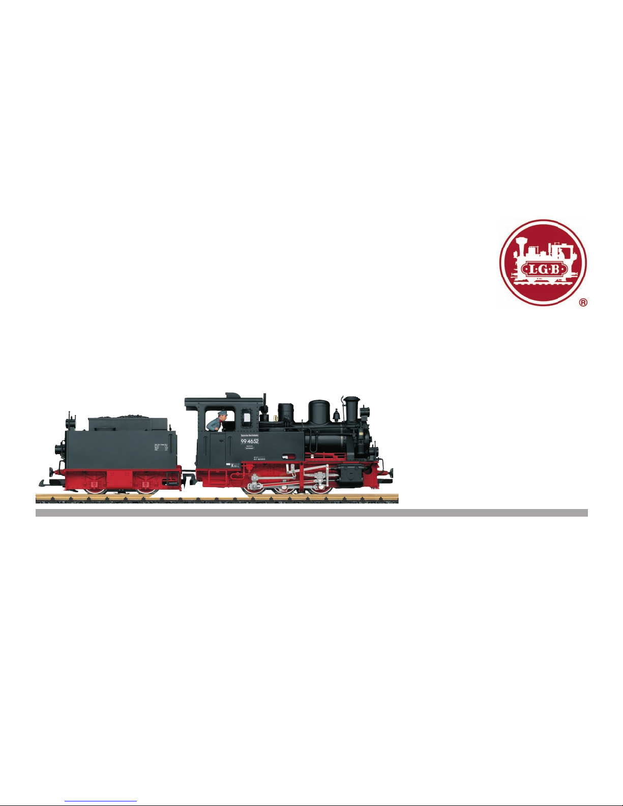
Namesetatthefactory:
99 4652
• Volumecanbechangedforthesoundeffects
Preparation
Couplethelocomotivetothetender:
• Plugtheconnectingwireforthelocomotiveintothesocketonthetenderandplug
thewirefromthetenderintothelocomotive.Donotgetthewiresmixedup!
• Hangthecouplerhookonthelocomotiveinthelooponthetender.
Mode of Operation Switch
This model has a four-position mode of operation switch in the tender under the right
waterhatch(Figure1).
Pos.0 Locomotivestoppedwithoutcurrent
Pos.1 Locomotivemotors,sound,andlightingareturnedon
Pos. 2 & 3 Same as Pos. 1
Sound
Thismodelhasavolumecontrollerinthetenderundertheleftwaterhatch(Figure2).
ThewhistleandthebellalsocanbetriggeredbytheLGBSoundMagnet(17050)in-
cludedwiththismodel.The17050snapsbetweenthetiesofmostLGBtracksections.
Themagnetinthe17050isundertheLGBlogo.Ifthecontactisinstalledwiththelogo
ontherightsideofthetrack(inthedirectionoftravel),itwilltriggerthewhistleasthe
modelpasses.Whenitissettotheotherside,thebellwillsound.
Multi-Protocol Operation
Analog Operation
This decoder can also be operated on analog layouts or areas of track that are
analog.Thedecoderrecognizesalternatingcurrent(DC)andautomaticallyadapts
to the analog track voltage. All functions that were set under mfx or DCC for analog
operationareactive(seeDigitalOperation).
Digital Operation
The decoders are multi-protocol decoders. These decoders can be used under the
followingdigitalprotocols:mfxorDCC.
The digital protocol with the most possibilities is the highest order digital protocol.
Thesequenceofdigitalprotocolsindescendingorderis:
Priority1:mfx;Priority2:DCC;Priority3:DC
Note:Digitalprotocolscaninuenceeachother.Fortrouble-freeoperation,were-
commend deactivating those digital protocols not needed by using CV 50. Deactivate
unneeded digital protocols at this CV if your controller supports this function.
Iftwoormoredigitalprotocolsarerecognizedinthetrack,thedecoderautomatically
takesonthehighestorderdigitalprotocol,example:mfx/DCC;thedecodertakeson
themfxdigitalprotocol(seeprevioustable).
Note: Please note that not all functions are possible in all digital protocols. Several
settingsforfunctions,whicharesupposedtobeactiveinanalogoperation,canbe
done under mfx and DCC.
Notes on digital operation
• Theoperatinginstructionsforyourcentralunitwillgiveyouexactproceduresfor
setting the different parameters.
• Thevaluessetatthefactoryhavebeenselectedformfx/DCCinordertoguarantee
the best possible running characteristics. Adjustments may have to be made for
other operating systems.
• Thesettingdoneatthefactorydoesnotpermitoperationwithoppositepolarity
DCpowerinthebrakingblock.Ifyouwantthischaracteristic,youmustdowithout
conventionalDCpoweroperation(CV29/Bit2=0).
mfx Protocol

11
Addresses
•Noaddressisrequired;eachdecoderisgivenaone-time,uniqueidentier(UID).
• ThedecoderautomaticallyregistersitselfonaCentralStationoraMobileStation
with its UID.
Programming
• ThecharacteristicscanbeprogrammedusingthegraphicscreenontheCentral
Station or also partially with the Mobile Station.
• AlloftheCongurationVariables(CV)canbereadandprogrammedrepeatedly.
• Theprogrammingcanbedoneeitheronthemaintrackortheprogrammingtrack.
• Thedefaultsettings(factorysettings)canbeproducedrepeatedly.
• Functionmapping:Functionscanbeassignedtoanyofthefunctionbut-
tonswiththehelpofthe60212CentralStation(withlimitations)andwiththe
60213/60214/60215CentralStation(SeehelpsectionintheCentralStation).
DCC Protocol
Addresses
• Shortaddress–longaddress–multipleunitaddress
• Addressrange:
1-127forshortaddressandmultipleunitaddress,
1 - 10239 for long address
• Everyaddresscanbeprogrammedmanually.
• ShortorlongaddressisselectedbymeansofCV29(Bit5).
•Amultipleunitaddressthatisbeinguseddeactivatesthestandardaddress.
Programming
• ThecharacteristicscanbechangedrepeatedlyusingtheCongurationVariables
(CV).
• TheCVnumbersandtheCVvaluesareentereddirectly.
• TheCVscanbereadandprogrammedrepeatedly.(Programmingisdoneonthe
programmingtrack.)
• TheCVscanbeprogrammedinanyorderdesired.(Programmingcanbedone
onthemaintrackPoM).ThePoMcanonlybedonewiththosedesignatedinthe
CV table. Programming on the main track PoM must be supported by your central
controller(Pleaseseethedescriptionforthisunit.).
• Thedefaultsettings(factorysettings)canbeproducedrepeatedly.
• 14/28or126speedlevelscanbeset.
• Allofthefunctionscanbecontrolledaccordingtothefunctionmapping(seeCV
description).
• SeetheCVdescriptionfortheDCCprotocolforadditionalinformation.
We recommend that in general programming should be done on the programming
track.

12
Maintenance
Lubrication
OiltheaxlebearingsandthesiderodbearingsnowandthenwithadropofMärklin
oil(itemno.7149).
Replacing Light Bulbs (E130023)
Lamps (front, above in the rear): Pull the lamp housing from the model. Pull the light
bulb from the socket. Insert the new light bulb. Put the model back together.
Lamps (lower rear): Remove the ring on the outside of the lamp glass. Carefully lift
the glass from the lantern. Pull the light bulb from the socket with a pair of tweezers.
Insert the new light bulb. Put the model back together.
Interior Lighting: Pull the light bulb from the socket with a pair of tweezers. Insert the
new light bulb.
Replacing Traction Tires (E126174)
- Remove the valve gear hanger between the first and second axle.
- Loosenthehexheadscrewsusedtomountthedriverodsandsiderodstothe
third axle.
- Thereareseveralscrewsontheundersideofthedrivegear:Removethesecond
and fifth screws from the front.
- Pull the drive gear out of the frame. Detach the wire.
- Useasmallatbladescrewdrivertochangethetractiontire:
- Lifttheoldtractiontirefromthegrooveinthedrivingwheel.
- Carefully push the new traction tire into the groove.
- Make sure that the traction tire is properly seated.
- Put the model back together.
Function Mapping
It is possible to assign functions controlled from the decoder to function buttons
ofyourchoice(mapping).Todothisanappropriatevaluemustbeenteredinthe
appropriate CV.
TheCVs(lines)andthefunctions(columns)arelistedinthetablesonpages42/43.
Four CVs belong to each button. For space reasons the 4 CVs were put together in
onelinestartingwithCV282(ButtonF5).
It is basically possible to assign several functions to one button or one function to
several buttons.
Note: The programming for function mapping should be done only by experienced
users.
Individual functions can be controlled by means of SUSI depending on the design of
the decoder. These functions can be handled by the decoder as sound. The volume
levels belonging to these functions cannot be changed.
Examples of Function Mapping:
AUX 2 is to be forwards and backwards on Function 3
CV272&CV372=8
CV273&CV373=0
CV274&CV374=0
CV275&CV375=0
Sound 15 is to be shifted from forwards and backwards on Function 3 to Function 8.
The existing function at Function 8 is overwritten in the process.
CV275&CV375=0
CV273&CV373=0
CV274&CV374=0
CV275&CV375=0
CV297&CV397=0
CV298&CV398=0
CV299&CV399=0
CV300&CV400=4
to Function 8
away from Function 3
forwards
backwards

13
Programming the CV with the 55015 Universal Hand Controller
ThedecoderbuiltintoyourlocomotiveisafurtherdevelopmentofthepreviousLGB
decoder-technology. A lot more functions are available on this decoder than was
previously customary. More possibilities for making settings on the decoder are how-
ever,necessarycomparedtopreviousdecodersinordertobeabletoadaptthese
functions to your personal needs. These settings can also be done with the 55015 Uni-
versal Hand Controller. Since the Universal Hand Controller was not designed for this
decoder,thecorrectprocedurewiththiscontrollerissomewhatmoreinvolved.
Webasicallyhavetodifferentiateamong3differentprogrammingmethods:
• Programmingbymeansofregisters(uptoCV5)
• ProgrammingbymeansofCVs(uptoCV255)
• Programmingbymeansofpages(uptoCV1024)
The individual programming processes are described below. There is a requirement
in each case that the programming module is plugged in and the locomotive with the
decoder is standing on the corresponding track.
Programming by means of Registers (Universal-Handy 55015)
CV1–5canbeprogrammedwhenprogrammingbymeansofregisters.
• Whentheprogrammingmoduleispluggedin,thehandcontrollerwill
show
--
.
• EnterthedesiredCVasatwo-digitnumber,example:„02“.
• Thehandcontrollerwillshow
d -
• Now,enterthedesiredvalueandconrmitbypressingonthearrow
button .
• Thehandcontrollerwillagainshow
--
.
The programming is complete and the desired value has been programmed into the
decoder.
Programming by means of CVs
ProgrammingbymeansofCVsonlyallowschangestoCVs1–5.Anothermethod
is necessary in order to program higher CVs. Programming by means of CVs allows
changestoCVs1–255.
Controllable Functions
Lighting* LV+LR
+AUX1
Soundeffect:Longlocomotivewhistle 1 Sound 1
Soundeffect:Squealingbrakesoff 2 BS
Soundeffect:Bell 3 Sound 3
Soundeffect:Stationannouncements 4 Sound 4
Soundeffect:Coalbeingshoveled 5 Sound 9
Soundeffect:Operatingsounds* 6 FS
Smoke generator * 7 Sound7+
Sound 16
Soundoff/on 8 Sound 14
ABV,off 9
Engineer‘s cab lighting 10 AUX 3
Lowspeedswitchingrange&DoubleAswitchinglight 11 LV+LR
+AUX1
Soundeffect:Shortlocomotivewhistle 12 Sound 2
Soundeffect:Injector 13 Sound 12
Soundeffect:Sanding 14 Sound 15
Soundeffect:Airpump 15 Sound 11
* active in analog operation
General Note to Avoid Electromagnetic Interference:
Apermanent,awlesswheel-railcontactisrequiredinordertoguaranteeoperation
for which a model is designed.
Do not make any changes to current-conducting parts.

14
Register Assignment Range Default
1 Address 1 – 127 3
2 Minimum speed 0 – 255 25
3 Acceleration delay 0 – 255 15
4 Braking delay 0 – 255 15
5 Maximum speed 0 – 255 255
8 Reset 8
13 Function F1 – F8 with alternative track signal 0 – 255 96
14 Function FL, F9 – F15 with alternative track signal 0 – 255 1
17 Expanded address, higher value byte 192 – 231 192
18 Expanded address, lower value byte 0 – 255 128
19 Multiple unit operation address 0 – 255 0
21 Functions F1 – F8 with multiple unit operation 0 – 255 0
22 Function FL, F9 – F15 with multiple unit operation 0 – 255 0
29
Bit 0: Direction normal/inverted
Bit 1: Number of speed levels 14/28(128)
Bit 2: Analog operation off/on
Bit 5: short / long address active
0/1
0/2
0/4
0/32
6
50
Alternative Formats
Bit 1: Analog DC
Bit 3: mfx off/on
0/2
0/8 10
53 Motor control – control reference 0 – 255 170
54 Motor control – control parameter K 0 – 255 16
55 Motor control – control parameter I 0 – 255 32
56 Motor control – control influence 0 – 255 42
57 Steam chuff 1 0
Register Assignment Range Default
58 Steam chuff 2 66
60
Multi-station announcement
Bit 0 – 3: Number of stations
Bit 4: Last announcement changes the sequence
Bit 5: Locomotive direction changes the sequence
Bit 6: Start for the sequence
0 – 15
0/16
0/32
0/64
1
63 Total volume 0 – 255 255
64 Threshhold for squealing brakes 0 – 255 55
67 – 94 Speed table for speed levels 1 – 28 0 – 255
112 Mapping lights in the front, mode 0 – 16 1
113 Mapping lights in the front, dimmer 0 – 255 255
114 Mapping lights in the front, cycle 0 – 255 20
115 – 135 Mapping phys. outputs, lights in the rear, Aux 1 – 6,
compare 112 – 114
0 – 16
0 – 255
137 Factor for switching range 1 – 128 128
138 Volume for squealing brakes 0 – 255 180
139 – 155 Volume for individual sounds 0 – 255 255
176 Minimum speed in analog DC 0 – 255 60
177 Maximum speed in analog DC 0 – 255 145
257 – 260 Function mapping Function FL forwards 0 – 255 257 = 5
262 – 265 Function mapping Function F1 forwards 0 – 255 263 = 16
267 – 270 Function mapping Function F2 forwards 0 – 255 268 = 4
272 – 275 Function mapping Function F3 forwards 0 – 255 273 = 64
277 – 280 Function mapping Function F4 forwards 0 – 255 278 = 128
282 – 285 Function mapping Function F5 forwards 0 – 255 284 = 16

15
Register Assignment Range Default
287 – 290 Function mapping Function F6 forwards 0 – 255 288 = 8
292 – 295 Function mapping Function F7 forwards 0 – 255 294 = 4
295 = 8
297 – 300 Function mapping Function F8 forwards 0 – 255 300 = 2
302 – 305 Function mapping Function F9 forwards 0 – 255 303 = 1
307 – 310 Function mapping Function F10 forwards 0 – 255 307 = 16
312 – 315 Function mapping Function F11 forwards 0 – 255 312 = 7
317 – 320 Function mapping Function F12 forwards 0 – 255 318 = 32
322 – 325 Function mapping Function F13 forwards 0 – 255 324 = 128
327 – 330 Function mapping Function F14 forwards 0 – 255 330 = 4
332 – 335 Function mapping Function F15 forwards 0 – 255 334 = 64
337 – 340 Function mapping standstill forwards 0 – 255
342 – 345 Function mapping running forwards 0 – 255
347 – 350 Function mapping Sensor 1 forwards 0 – 255
352 – 355 Function mapping Sensor 2 forwards 0 – 255
357 – 360 Function mapping Function FL backwards 0 – 255 357 = 2
362 – 365 Function mapping Function F1 backwards 0 – 255 363 = 16
367 – 370 Function mapping Function F2 backwards 0 – 255 368 = 4
372 – 375 Function mapping Function F3 backwards 0 – 255 373 = 64
377 – 380 Function mapping Function F4 backwards 0 – 255 378 = 128
382 – 385 Function mapping Function F5 backwards 0 – 255 384 = 16
387 – 390 Function mapping Function F6 backwards 0 – 255 388 = 8
392 – 395 Function mapping Function F7 backwards 0 – 255 394 = 4
395 = 8
Register Assignment Range Default
397 – 400 Function mapping Function F8 backwards 0 – 255 400 = 2
402 – 405 Function mapping Function F9 backwards 0 – 255 403 = 1
407 – 410 Function mapping Function F10 backwards 0 – 255 407 = 16
412 – 415 Function mapping Function F11 backwards 0 – 255 412 = 7
417 – 420 Function mapping Function F12 backwards 0 – 255 418 = 32
422 – 425 Function mapping Function F13 backwards 0 – 255 424 = 128
427 – 430 Function mapping Function F14 backwards 0 – 255 430 = 4
432 – 435 Function mapping Function F15 backwards 0 – 255 434 = 64
437 – 440 Function mapping standstill forwards backwards 0 – 255
442 – 445 Function mapping running forwards backwards 0 – 255
447 - 450 Function mapping Sensor 1 backwards 0 – 255
452 – 455 Function mapping Sensor 2 backwards 0 – 255

16
Remarques importantes sur la sécurité
• Lalocomotivenepeutêtreutiliséequ‘aveclesystèmed‘exploitationindiqué.
• Utiliseruniquementdesconvertisseursettransformateurscorrespondantàla
tension du secteur local.
• Lalocomotivenepeutêtrealimentéeencourantqueparuneseulesourcedecourant.
• Veuillezimpérativementrespecterlesremarquessurlasécuritédécritesdansle
mode d’emploi de votre système d’exploitation.
• Neconvientpasauxenfantsdemoinsde15ans.
• ATTENTION! Pointes et bords coupants lors du fonctionnement du produit.
Information importante
• Lanoticed‘utilisationfaitpartieintégranteduproduit;elledoitdoncêtreconser-
véeet,lecaséchéant,transmiseavecleproduit.
• Pourtouteréparationouremplacementdepièces,adressez-vousàvotre
détaillant-spécialisteLGB.
• Elimination:www.maerklin.com/en/imprint.html
Fonctionnement
• Lemodèleestprévupourêtreexploitésurdessystèmesdeuxrailsc.c.LGBavec
despupitresdecommandesLGBclassiquesencourantcontinu(DC,0-24V).
• Décodeurmultiprotocolaire(DC,DCC,mfx)intégré.
• Pourl’utilisationaveclesystèmemultitrainLGB(DCC),lemodèleestprogrammé
surl’adresse03.Enmoded’exploitationmfx,lalocomotiveestreconnueautoma-
tiquement.
• TechnologiemfxpourMobileStation/CentralStation.
Nomencodeeenusine:99 4652
• Volumedesbruitagesréglable
Préparation
Attelerlalocomotiveautender:
• Encherlecâblederaccordementdelalocomotivedanslaprisedutenderetle
câbledutenderdanslaloco.Veillerànepaspermuterlescâbles!
• Accrocherlecrochetd’attelagedelalocodansl’étrierdutender.
Commutateur de sélection du mode d’exploitation
Lemodèledisposed’uncommutateuràquatrepositionspourlasélectiondumode
d’exploitationsituédansletender,souslecouvercledesouteàeaudroit(g.1).
Pos.0 Locomotivegaréehorstension
Pos.1 Moteursdelaloco,sonetéclairagesontactivés
Pos. 2 & 3 Idem Pos. 1
Effets sonores
Lemodèledisposed’unrégulateurduvolumesonoresituédansletender,sousle
couvercledesouteàeaugauche(g.2).Lesifetpeutégalementêtredéclenchépar
l’aimantcommutateurdesonLGB(17050)fourniaveccemodèleréduit.L’accessoire
17050semetenplaceentrelestraversesdelaplupartdessectionsdevoieLGB.L’aimant
del’accessoire17050setrouvesouslelogoLGB.Silecontactestinstalléaveclelogodu
côtédroitdelavoie(danslesensdelamarche),ildéclencheralesifetaupassagedu
modèleréduit.Sil’aimantestplacédel’autrecôté,ildéclenchelebruitdelacloche.
Mode multiprotocole
Mode analogique
On peut aussi faire fonctionner le décodeur sur des installations ou des sections de
voieanalogiques.Ledécodeuridentieautomatiquementlatensiondevoieanalo-
gique(CC).Touteslesfonctionsquiontétéparamétréepourlemodeanalogiquesous
mfxousousDCCsontactives(voirmodenumérique).
Mode numérique
Lesdécodeursontdesdécodeurmultiprotocole.Ledécodeurpeutêtreutiliséavec
lesprotocolesnumériquessuivants:mfx,DCC
Leprotocolenumériqueoffrantlespossibilitéslesplusnombreusesestleprotocole
numériqueàbitdepoidsfort.Lahiérarchisationdesprotocolesnumériquesest
descendante:Priorité1:mfx;Priorité2:DCC,Priorité3:
DC
Indication : des protocoles numériques peuvent s’influencer réciproquement. Pour
uneexploitationsansperturbations,nousrecommandonsdedésactiveravecCV50
des protocoles numériques non nécessaires. Dans la mesure où votre centrale les
supporte,désactivezyaussilesprotocolesnumériquesnonnécessaires.
Lorsquedeuxouplusieursprotocolesnumériquessontidentiésauniveaudela
voie,ledécodeurreprendautomatiquementleprotocolenumériqueàbitdepoids
fort,p.ex.mfx/DCC.Leprotocolenumériquemfxestdoncreprisparledécodeur(voir
tableauantérieur).
Indication :remarquezquetouteslesfonctionsnepeuventpasêtreactionnéesdans
touslesprotocolesnumériques.SousmfxetsousDCC,ilestpossibledeprocéderà
quelquesparamétragesdefonctionsdevantêtreactivesdanslecadredel’exploita-
tion analogique.
Remarques relatives au fonctionnement en mode digital
• Encequiconcernelaprocédurederéglagedesdiversparamètres,veuillezvous
référer au mode d‘emploi de votre centrale de commande multitrain.
• Lesvaleursparamétréesd’usinesontchoisiespourmfx/DCCdemanièreà
garantir le meilleur comportement de roulement possible. Pour d’autres systèmes
d’exploitation,cesvaleursdevrontéventuellementêtreadaptées.
• L’exploitationaveccourantcontinudepolaritéinversedanslessectionsdefreina-

17
gen’estpaspossibleavecleréglaged’usine.Sicettepropriétéestdésirée,ilfaut
alorsrenonceràl’exploitationconventionnelleencourantcontinu(CV29/Bit2=0).
Protocole mfx
Adressage
• Aucuneadressen’estnécessaire,ledécodeurreçoittoutefoisuneidentication
uniqueetnonéquivoque(UID).
• AvecsonUID,ledécodeurindiqueautomatiquementàunestationcentraleouà
une station mobile qu’il est connecté.
Programmation
• Lescaractéristiquespeuventêtreprogramméesparl’intermédiairedelacouche
graphiquedelastationcentrale,voireenpartieaussiaumoyendelastationmobile.
• Touteslescongurationsvariables(CV)peuventêtreluesetprogramméesde
façonréitérée.
• Laprogrammationpeutêtreréaliséesoitsurlavoieprincipale,soitsurlavoiede
programmation.
• Lesparamétragespardéfaut(paramétragesusine)peuventêtrerétablis.
• Mappagedesfonctions:lesfonctionspeuventêtreaffectéesàdequelconques
touchesdefonctionaumoyendelastationcentrale(60212)(restreinte)etavecla
stationcentrale60213/60214/60215(voirAideauniveaudelastationcentrale).
Protocole DCC
Adressage
• Adressebrève–adresselongue–adressedetraction.
• Champd’adresse:
1–127adressebrève,adressedetraction
1–10239adresselongue
• Chaqueadresseestprogrammablemanuellement.
• UneadressecourteoulongueestsélectionnéevialaCV29(bit5).
• Uneadressedetractionutiliséedésactivel’adressestandard.
Programmation
• Lescaractéristiquespeuventêtremodiéesdefaçonréitéréeparl’intermédiaire
desvariablesdeconguration(CVs).
• Touteslescongurationsvariables(CV)peuventêtreluesetprogramméesde
façonréitérée.
• Laprogrammationpeutêtreréaliséesoitsurlavoieprincipale,soitsurlavoiede
programmation.
• LesCVspeuventêtreprogramméeslibrement(programmationdelavoieprincipale
(PoM).LaPoMn’estpossiblequepourlesCVsidentiéesdansletableaudes
CVs.Laprogrammationsurlavoieprincipale(PoM)doitêtresupportéeparvotre
centrale(voirmoded’emploidevotreappareil).
• Lesparamétragespardéfaut(paramétragesusine)peuventêtrerétablis.
• 14/28,voire128cransdemarchesontparamétrables.
• Touteslesfonctionspeuventêtrecommutéesenfonctiondumappagedesfonc-
tions(voirledescriptifdesCVs).
• Pourtouteinformationcomplémentaire,voirletableaudesCVs,protocoleDCC.
Ilestrecommandé,deréaliserlaprogrammation,fondamentalement,surlavoiede
programmation.

18
Mapping des fonctions
Lesfonctionscommandéesparledécodeurpeuventêtrelibrementaffectéesaux
différentestouchesdefonctions(mapping).Aceteffet,ilfautenregistrerunevaleur
correspondante dans la CV correspondante.
Letableaudespages42et43établitunelistedesCV(lignes)etdesfonctions
(colonnes).Achaquetouchecorrespondent4CV.Pourdesraisonsdeplace,les4CV
correspondantàchaquetoucheontétéregroupéessuruneseuleligneàpartirdela
CV282(toucheF5).
Enprincipe,plusieursfonctionspeuventêtreaffectéesàunemêmetouche,resp.une
mêmefonctionpeutêtreaffectéeàplusieurstouches.
Remarque :Laprogrammationdumappingdefonctionsestréservéeauxutilisateurs
avertis.
Enfonctiondelacongurationdudécodeur,lesdifférentesfonctionspeuventêtre
commandées via SUSI. Ces fonctions sont traitées par le décodeur en tant que
bruitage.Levolumecorrespondantnepeutalorspasêtremodié.
Exemples de mapping de fonctions:
AUX2doitêtreaffectéàFonction3enavantetenarrière
CV272&CV372=8
CV273&CV373=0
CV274&CV374=0
CV275&CV375=0
Lebruitage15doitêtretransposédelafonction3enavantetenarrièresurlafonc-
tion8.L’affectationexistantedelafonction8doitdoncêtresupprimée.
CV275&CV375=0
CV273&CV373=0
CV274&CV374=0
CV275&CV375=0
CV297&CV397=0
CV298&CV398=0
CV299&CV399=0
CV300&CV400=4
Entretien
Graissage
Graissezrégulièrementlaboîted’essieuxetleroulementdelatringlerieavecune
goutted’huileMärklin(réf.7149).
Remplacer les lampes incandescentes (E130023)
Lampes (en haut avant/arrière):Retirerleboîtierdelalampedumodèle.Retirer
l’ampoule incandescente de son socle. Enficher la nouvelle ampoule. Remonter le
modèle.
Lampes (en bas, à l’arrière) : Retirerl’anneausituéàl’extérieurduverredelalampe.
Enfaisantlevier,souleverdélicatementleverredelalanterne.Al’aided’unepincet-
te,retirerl’ampouleenchéedansladouille.Enfoncerlanouvelleampoule.Remonter
le modèle.
Eclairage intérieur:Àl’aided’unepincette,retirerl’ampouledeladouille.Encherla
nouvelle ampoule.
Remplacer le bandage d’adhérence (E126174)
- Retirer la fixation de la tringlerie entre le premier et le deuxième essieu.
- Défairelesvisàtêtehexagonalexantl’embiellagesurletroisièmeessieu.
- Souslatransmissionsetrouventplusieursvis:Défaireladeuxièmeetlacinquième
vis en partant de l’avant.
- Retirerlatransmissionducadre.Retirerlecâble.
-Al’aided’unpetittournevisplat,retirerlebandaged‘adhérence:
- Fairelevierpoursortirlebandaged’adhérenceusédelarainure(cannelure)dela
roue motrice.
- Pousserdélicatementlenouveaubandaged’adhérencedanslarainure(canne-
lure)delaroue.
- Vérifier qu’il est bien mis.
- Remonter le modèle.
Vers la fonction 8
Sortir de la fonction 3
En avant
En arrière

19
Programmation des CV avec le Universal-Handy 55015
Ledécodeurintégrédansvotrelocomotiveestuneversionamélioréedel’ancien
décodeurLGB.Lesfonctionsdisponiblessontdoncbienplusnombreusesque
jusqu’alors.
Or,l’adaptationdecesfonctionsauxbesoinsdechacunnécessiteégalement
davantagedepossibilitésdeparamétrageparrapportauxanciensdécodeurs.Le
paramétragepeutégalementêtreeffectuéàpartirdelacommandeuniverselle
(Universal-Handy)réf.55015.LeUniversal-Handyn’étanttoutefoispasconçupour
cesdécodeurs,laprocédurecorrectes’avèreunpeupluscomplexe.
Ondistingueenprincipe3méthodesdeprogrammationdifférentes:
• Programmationviaregistres(jusqu‘àCV5)
• ProgrammationviaCV(jusqu‘àCV255)
• Programmationviapages(jusqu‘àCV1024)
Ces différentes procédures de programmation sont décrites dans le paragraphe
suivant. Chaque procédure suppose que le module de programmation est branché et
que la locomotive équipée de son décodeur se trouve sur la voie correspondante.
Programmation via registres (Universal-Handy 55015)
LaprogrammationviaregistrespermetdeprogrammerlesCV1à5.
• Quandlemoduledeprogrammationestbranché,leHandyafche
--
.
• EntrezlaCVsouhaitéeavecdeuxchiffres,parex.«02».
• LeHandyafche
d -
• Entrezlavaleursouhaitéeetappuyezsurlatoucheèche .
• LeHandyafcheànouveau
--
.
Laprogrammationestterminée,lavaleursouhaitéeaétéprogramméedansle
décodeur.
Programmation via CV
LaprogrammationviaregistrespermetuniquementdemodierlesCVsà1à5.La
programmationdeCVssupérieuresnécessiteuneautreméthode.Laprogrammation
viaCVpermetdemodierlesCVs1à255.
Fonctions commutables
Eclairage * LV+LR
+AUX1
Bruitage:Sifetlocomotivelong 1 Sound 1
Bruitage:Grincementdefreinsdésactivé 2 BS
Bruitage:Cloche 3 Sound 3
Bruitage:Annonceengare 4 Sound 4
Bruitage:Pelletageducharbon 5 Sound 9
Bruitage:Bruitd’exploitation* 6 FS
Générateurdefumée
* 7 Sound7+
Sound 16
Marche/arrêtdusystèmed’effetssonores 8 Sound 14
ABV,désactivé 9
Eclairage de la cabine de conduite 10 AUX 3
Vitesse de manœuvre & Feu de manœuvre double A 11 LV+LR
+AUX1
Bruitage:Sifetlocomotivecourt 12 Sound 2
Bruitage:Injecteur 13 Sound 12
Bruitage:Sablage 14 Sound 15
Bruitage:Compresseur 15 Sound 11
* activée en mode d’exploitation analogique
Indication d‘ordre général pour éviter les interférences électromagnétiques:
Lagarantiedel‘exploitationnormalenécessiteuncontactroue-railpermanentet
irréprochable.
Neprocédezàaucunemodicationsurdesélémentsconducteursdecourant.

20
Registres Affectation Domaine Valeur
par
défaut
1 Adresse 1 – 127 3
2 Vitesse minimale 0 – 255 25
3 Temporisation de démarrage 0 – 255 15
4 Temporisation de freinage 0 – 255 15
5 Vitesse maximale 0 – 255 255
8 Réinitialisation 8
13 Fonction F1à F8 pour signal de voie alternatif 0 – 255 96
14 Fonction FL, F9 à f15 pour signal de voie alternatif 0 – 255 1
17 Adresse avancée, byte supérieur 192 – 231 192
18 Adresse avancée, byte inférieur 0 – 255 128
19 Adresse traction 0 – 255 0
21 Fonctions F1 à F8 pour traction 0 – 255 0
22 Fonction FL, F9 à F15 pour traction 0 – 255 0
29
Bit 0 : Sens de marche normal/inversé
Bit 1: Nombre de crans de marche 14/28(128)
Bit 2: Mode analogique désactivé/activé
Bit 5: Adresse courte/longue activée
0/1
0/2
0/4
0/32
6
50 Formats alternatifs
Bit 1: Analogique c.c.
Bit 3: Mfx désactivé/activé
0/2
0/8 10
53 Régulation du moteur – référence de régulation 0 – 255 170
54 Régulation du moteur - paramètre de régulation K 0 – 255 16
55 Régulation du moteur – paramètre de régulation I 0 – 255 32
56 Régulation du moteur – influence de régulation 0 – 255 42
57 Plan de vapeur 1 0
Registres Affectation Domaine Valeur
par
défaut
58 Plan de vapeur 2 66
60
Annonce en gare multiple
Bit 0 à 3: Nombre des gares
Bit 4: Annonce finale modifie l’ordre
Bit 5: Sens de marche de la loco modifie l’ordre
Bit 6: Ordre par défaut
0 – 15
0/16
0/32
0/64
1
63 Volume global 0 – 255 255
64 Seuil pour grincement de frein 0 – 255 55
67 – 94 Tableau de vitesse, crans de marche 1 à 28 0 – 255
112 Mapping éclairage avant, mode 0 – 16 1
113 Mapping éclairage avant, variateur 0 – 255 255
114 Mapping éclairage avant, période 0 – 255 20
115 – 135 Mapping sorties phys., éclairage arrière, Aux 1 à 6,
cf. 112 à 114
0 – 16
0 – 255
137 Facteur vitesse de manoeuvre 1 – 128 128
138 Volume grincement de frein 0 – 255 180
139 – 155 Volume individuel des différents bruitages 0 – 255 255
176 Vitesse minimale analogique c.c. 0 – 255 60
177 Vitesse maximale analogique c.c. 0 – 255 145
257 – 260 Mapping de fonctions fonction FL en avant 0 – 255 257 = 5
262 – 265 Mapping de fonctions fonction F1 en avant 0 – 255 263 = 16
267 – 270 Mapping de fonctions fonction F2 en avant 0 – 255 268 = 4
272 – 275 Mapping de fonctions fonction F3 en avant 0 – 255 273 = 64
277 – 280 Mapping de fonctions fonction F4 en avant 0 – 255 278 = 128
Table of contents
Languages:
Other LGB Toy manuals
Popular Toy manuals by other brands

Otto DIY
Otto DIY Otto instruction manual

Millennium
Millennium MICRO-SSX Assembly instructions

Freewing
Freewing Eurofighter Typhoon V2 user manual

Kogan
Kogan KASPCRLGLWB user guide

The Wand Company
The Wand Company Star Trek Phaser Remote Replica Instructions for use

LEGO
LEGO DC Comics Super Heroes 76012 Assembly instructions

LEGO
LEGO 41063 Instruction

KidKraft
KidKraft 65023C Assembly instructions

MTB
MTB Balm050 instruction manual

Our Generation
Our Generation OG Pizza Oven Playset BD37953 instruction manual

Mega Construx
Mega Construx Saban's Power Rangers T-Rex Zord DPK75 Assembly instructions

3M
3M Guggenheim Assembly instructions