manuals.online logo
Brands
  1. Home
  2. •
  3. Brands
  4. •
  5. Lightolier
  6. •
  7. Light Fixture
  8. •
  9. Lightolier Lytecaster 1100F Series User manual

Lightolier Lytecaster 1100F Series User manual

Other Lightolier Light Fixture manuals
Lightolier Calculite ProSpec PB4P3075 User manual

Lightolier

Lightolier Calculite ProSpec PB4P3075 User manual

Lightolier Calculite ProSpec PA3H3039 User manual

Lightolier

Lightolier Calculite ProSpec PA3H3039 User manual

Lightolier Calculite C6P38MH User manual

Lightolier

Lightolier Calculite C6P38MH User manual

Lightolier PRISMALYTE plus PRA2GRFVA26U User manual

Lightolier

Lightolier PRISMALYTE plus PRA2GRFVA26U User manual

Lightolier Lytespan 8338 User manual

Lightolier

Lightolier Lytespan 8338 User manual

Lightolier 1101FIC User manual

Lightolier

Lightolier 1101FIC User manual

Lightolier Lytespan 23F20BT User manual

Lightolier

Lightolier Lytespan 23F20BT User manual

Lightolier Lytecaster 1035 User manual

Lightolier

Lightolier Lytecaster 1035 User manual

Lightolier Luminosities 40886 User manual

Lightolier

Lightolier Luminosities 40886 User manual

Lightolier SL203A User manual

Lightolier

Lightolier SL203A User manual

Lightolier Lytecel-EL EL4MF10LX228 User manual
Lightolier

Lightolier Lytecel-EL EL4MF10LX228 User manual

Lightolier Calculite ProSpec PB2T4 User manual

Lightolier

Lightolier Calculite ProSpec PB2T4 User manual

Lightolier DSS01 User manual

Lightolier

Lightolier DSS01 User manual

Lightolier 4F35 User manual

Lightolier

Lightolier 4F35 User manual

Lightolier Decorative Visor 1 40618U User manual

Lightolier

Lightolier Decorative Visor 1 40618U User manual

Lightolier Lytecaster 2026WH User manual

Lightolier

Lightolier Lytecaster 2026WH User manual

Lightolier Brisa FB5114U User manual

Lightolier

Lightolier Brisa FB5114U User manual

Lightolier Calculite 8038 User manual

Lightolier

Lightolier Calculite 8038 User manual

Lightolier RADIANCE PENDANT FIXTURES Guide

Lightolier

Lightolier RADIANCE PENDANT FIXTURES Guide

Lightolier Prospec 26190 User manual

Lightolier

Lightolier Prospec 26190 User manual

Lightolier D13 User manual

Lightolier

Lightolier D13 User manual

Lightolier Calculite C6T6A-MHT6RF User manual

Lightolier

Lightolier Calculite C6T6A-MHT6RF User manual

Lightolier Calculite 8068 User manual

Lightolier

Lightolier Calculite 8068 User manual

Lightolier Calculite C6E17OHW User manual

Lightolier

Lightolier Calculite C6E17OHW User manual

Popular Light Fixture manuals by other brands

Veko Magnus manual

Veko

Veko Magnus manual

Cooper Lighting Halo L10538 specification

Cooper Lighting

Cooper Lighting Halo L10538 specification

Emos CLASSIC ZY1431T manual

Emos

Emos CLASSIC ZY1431T manual

Westinghouse Outdoor Lighting Fixture owner's manual

Westinghouse

Westinghouse Outdoor Lighting Fixture owner's manual

Hedler C 12 silent Operation manual

Hedler

Hedler C 12 silent Operation manual

Blizzard Lighting Puck: CSI manual 

Blizzard Lighting

Blizzard Lighting Puck: CSI manual 

Energetic Lighting ELYSL-5004 Series installation instructions

Energetic Lighting

Energetic Lighting ELYSL-5004 Series installation instructions

Lightmaxx Shaft 5R user manual

Lightmaxx

Lightmaxx Shaft 5R user manual
Triarch 31083 Assembly instructions

Triarch

Triarch 31083 Assembly instructions

Philips 32614 Series user manual

Philips

Philips 32614 Series user manual

IKEA TIVED Assembly instructions

IKEA

IKEA TIVED Assembly instructions

Chauvet Professional ROGUE R1 BEAM WASH user manual

Chauvet Professional

Chauvet Professional ROGUE R1 BEAM WASH user manual

Martin MAC 250 Krypton user manual

Martin

Martin MAC 250 Krypton user manual

Cooper Lighting Halo L3232E Specification sheet

Cooper Lighting

Cooper Lighting Halo L3232E Specification sheet

Stageline ODW-2410RGBW instruction manual

Stageline

Stageline ODW-2410RGBW instruction manual

ArtFox Beam 15R extreme manual

ArtFox

ArtFox Beam 15R extreme manual

GLG multispot 330 user manual

GLG

GLG multispot 330 user manual

Home Accents Holiday TY052-1924-1 Assembly instructions

Home Accents Holiday

Home Accents Holiday TY052-1924-1 Assembly instructions

manuals.online logo
manuals.online logoBrands
  • About & Mission
  • Contact us
  • Privacy Policy
  • Terms and Conditions

Copyright 2025 Manuals.Online. All Rights Reserved.

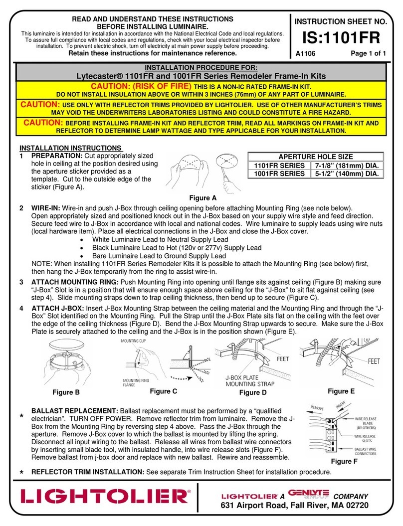
NEW CONSTRUCTION
1. FRAME-IN (FIG. A)
WOOD JOIST/METAL STUD CONSTRUCTION (FIG. E): Line up bot-
tom edge of ADJUSTABLE MOUNTING BAR with bottom of wood joist.
Fasten MOUNTING FRAME to
wood joist by nailing MOUNTING BAR
TAB or nail into joist.
SUSPENDED GRID CEILING (FIG. G):
Position notched area of ADJUSTABLE MOUNTING BARS on top of T-
BAR for proper spacing to finished ceiling. Lock MOUNTING BARS by
bending TAB underneath T-BAR BEAD (Fig. G1). For round T-BAR BEAD,
use screws to lock MOUNTING BARS (Fig. G2).
WIRE TO SUPPLY LEADS:
For cable, use built-in cable clamp in J-Box. Connect white fixture
leads to neutral (white) supply leads. Black fixture leads to hot (black)
supply leads. Bare fixture wire to supply ground. Use wirenuts (local
hardware item). Place all electrical connections in the J-Box, attach J-
Box cover.
NOTE: ADJUSTABLE MOUNTING BARS are pre-assembled on long side of
MOUNTING FRAME for rigidity and ease of installation (Fig. E).
MOUNTING BARS must be removed and installed on narrow side of
MOUNTING FRAME if installing in 16” joist spacing (Fig. F).
MOUNTING BARS can be extended to 24”. The MOUNTING FRAME
can be mounted off-center.
For suspended ceilings, make certain that bottom of MOUNTING
FRAME is no higher than 1” above finished ceiling (Fig. G).
2. CLOSE-IN (FIG. B)
Install plasterboard or other dry type ceiling. Hole in board can be cut
either on floor or after the board is secured in the ceiling. Use MOUNT-
ING FRAME opening as cutting guide template for hole – make sure
ROTO CLIPS are rotated out of hole area.
NOTE: For wet plaster ceiling, use Plaster Ring Accessory No. 1961 - order
separately.
3. SNAP-ON (FIG. C) See separate instruction sheet
4. PUSH-UP (FIG. D) for your choice of reflector trim.
®
READ AND UNDERSTAND THESE INSTRUCTIONS BEFORE INSTALLING FIXTURE.
This fixture is intended for installation in accordance with the National Electrical Code and local or Federal
code specifications. To assure full compliance with codes and regulations, check with your local electrical
inspector before installation. To prevent electrical shock, turn off electricity at fuse box before proceeding.
Retain these instructions for maintenance reference.
INSTRUCTION SHEET NO.
IS:1100F
D0605 Page 1of 2
Installation of Lytecaster®Frame-in-Kit 1100F Series
WARNING – (RISK OF FIRE) Do not install insulation within 3 inches of fixture sides or wiring
compartments, nor above fixture in such a manner as to entrap heat.
LOCKING SCREW
LINE UP BOTTOM
EDGE WITH BOTTOM
OF WOOD JOIST
MOUNTING FRAME
CENTERING SLOTS
ADJUSTABLE
MOUNTING BARS
T-BAR
1" MAX
1-1/2" MAX.
G1 G2
Fig. G
Fig. E
ADJUSTABLE MOUNTING BARS MOUNTING FRAME
(NARROW SIDE)
LINE UP BOTTOM EDGE WITH
BOTTOM OF WOOD JOIST
Fig. F
ADJUSTABLE MOUNTING BARS
Fig. A
1. Frame-In Fig. B
2. Close-in Fig. C
3. Snap-On Fig. D
4. Push-Up
LIGHTOLIER a GENLYTE company.
631 Airport Road, Fall River, MA 02720
INSTRUCTION SHEET NO.
IS:1100F
D0605 PAGE 2OF 2
READ AND UNDERSTAND THESE INSTRUCTIONS BEFORE INSTALLING FIXTURE.
This fixture is intended for installation in accordance with the National Electrical Code and local or Federal
code specifications. To assure full compliance with codes and regulations, check with your local electrical
inspector before installation. To prevent electrical shock, turn off electricity at fuse box before proceeding.
Retain these instructions for maintenance reference.
®
MOUNTING FRAME
BRIDGE
SLOT
Fig. H
ROTO CLIP
STAPLE
MOUNTING FRAME
CEILING MATERIAL
Fig. I
FRAME
J-BOX COVER
J-BOX
J-BOX SPRING
J-BOX COVER
Fig. J
BALLAST REPLACEMENT (FIG. J)
NOTE: Ballast replacement must be provided by a “qualified electrician”.
1. TURN OFF POWER.
2. Remove reflector trim from FRAME-IN KIT.
3. Remove J-BOX COVER nearest ceiling opening by lifting SPRING.
4. Disconnect all input wiring to ballast.
5. Remove BALLAST ASSEMBLY from J-BOX by pulling SPRING upward
(Fig. J).
6. Remove BALLAST ASSEMBLY through ceiling opening.
7. Release all wires from BALLAST WIRE CONNECTORS by inserting small
blade tool, with insulated handle, into WIRE RELEASE SLOTS. (Fig K).
NOTE: Replacement ballast kits generally are supplied with this special
wire release tool.
8. Remove (2) NUTS which hold BALLAST to J-BOX COVER.
9. Replace old BALLAST with new BALLAST and attach with NUTS
to J-BOX COVER.
10.Reassemble new BALLAST ASSEMBLY to J-BOX by snapping
onto J-BOX spring (Fig. J).
11.Rewire fixture. See WIRING DIAGRAM on BALLAST LABEL.
EXISTING CONSTRUCTION
Fig. A
1. Cut-Opening Fig. B
2. Wire-in Fig. C
3. Put Through Fig. D
4. Anchor Fig. F
6. Push-up
Fig. E
5. Snap-on
LIGHTOLIER a GENLYTE company.
631 Airport Road, Fall River, MA 02720
REMOVE
INSERT
BALLAST WIRE
CONNECTORS
WIRE RELEASE
BLADE
(BY OTHERS)
WIRE RELEASE
SLOTS
1. CUT OPENING (FIG. A AND FIG H)
a. Remove ADJUSTABLE MOUNTING BARS.
b. Use MOUNTING FRAME opening as template.
c. Break off BRIDGE on MOUNTING FRAME as shown in
Fig. H by breaking WEBS on SLOTS with cutting plier.
2. WIRE-IN (FIG. B)
For cable, use built in Cable Clamp in J-BOX. Connect white fixture
lead to neutral (white) supply lead. Black fixture leads to hot (black)
supply lead. Bare copper and/or green insulated wire(s) must all be
connected to supply ground. Use wire nuts (local hardware items).
Place all electrical connections in the
J-BOX. Attach J-BOX COVER onto J-BOX.
3. PUT THROUGH (FIG. C AND FIG. J)
Detach BALLAST ASSEMBLY from J-BOX and pass MOUNTING
FRAME into ceiling as shown in Fig. C. Reattach BALLAST ASSEMBLY.
4. ANCHOR (FIG. D AND FIG. I)
Using STAPLE (order separately Cat. #1985S), slide long end under-
neath raised embossing and short leg into ceiling (Fig. I).
5. SNAP-ON (FIG. E) See separate instruction sheet
6. PUSH-UP (FIG. F) for your choice of reflector trim.