manuals.online logo
Brands
  1. Home
  2. •
  3. Brands
  4. •
  5. Lilin
  6. •
  7. IP Camera
  8. •
  9. Lilin D/N HD AF IR IP CAMERA User manual

Lilin D/N HD AF IR IP CAMERA User manual

DC12V
GND
—
N.O.
COM.
DIN
GND
AIN
GND
AOUT
—485
+485
Installation Guide
Part Description & Dimensions
D/N HD AF IR IP CAMERA
66-8022CSE-1B
372
12
16 5
4
3
2
7
1110
333
182
116
8
9
112
ø95
84
84
13
14
15
1617
Top Case
Bottom Case
Lens
Sun Shield
Bottom Box
Top Box
Side Hole
Bottom Hole
Hole Plug
Adjustment Screw A
Adjustment Screw B
Adjustment Screw C
Factory default button
Restores the server back to factory default settings.
Micro SD card slot
Auto Focus button
Live Video Output Connector
LED Indicators
Green (Power): Indicates system status.
Green (Link): Illuminates when the camera is
connected to a network
Orange (ACT): Flashes when data communication
is in process.
1
2
3
4
5
6
7
8
9
10
11
12
13
14
15
16
17
The IP camera will automatically adjusts the camera lens to obtain focus after press
the AF (Auto Focus) button continuously for 2 seconds. User can adjust the image
view by using zoom in/out button via web access, and refocus using the Auto-Focus
link on the main Web page.
Installation
1. Remove the camera from the box. Separate the bottom box from the top box using
a torx wrench (FIG.1), and remove the safety cable on the bottom box (FIG.2).
2. Secure the bottom box to anywhere you want by tightening the included truss-head
screws (M4.0x25) to the mounting holes marked “a” on the bottom box (FIG.3&4).
FIG.1 FIG.2
FIG.3 FIG.4
a a
a a
FIG.5 FIG.6
4. Attach the safety cable to the mounting hole on the bottom box (FIG.7), and
connect the network cable and power cable to the camera’s RJ-45 connector
and power input, respectively (FIG.8).
FIG.7 FIG.8
+12V IN
GND
–
N.O.
COM.
DIN
GND
AIN
GND
AOUT
–485
+485
5. Use a torx wrench to lock the top box to the bottom box by tightening the screws
(FIG.9&10).
FIG.9 FIG.10
3. Firstly, insert the network cable and power cable through a pipe with ½" PT
(FIG.5), and then secure the pipe to the side hole or bottom hole (FIG.6. please
make sure the connection between the pipe and the side hole is watertight, and
the side hole is facing downwards).
6. Adjust the three adjustment screws to turn the camera to the desired position.
Then tighten the screws (FIG.11-16).
FIG.11 FIG.12
FIG.13 FIG.14
FIG.15 FIG.16
Change the Outlet Position for the Network Cable and Power Cable
1. Loosen the hole plug on the bottom box and secure it to the side hole (FIG.17).
Unit: mm
2.Insert the network cable and power cable through bottom hole on the bottom box
(FIG.18), and then connect the network cable and power cable to the camera’s
RJ-45 connector and power input, respectively (FIG.8). For watertight installation,
please refer to Installation-3.
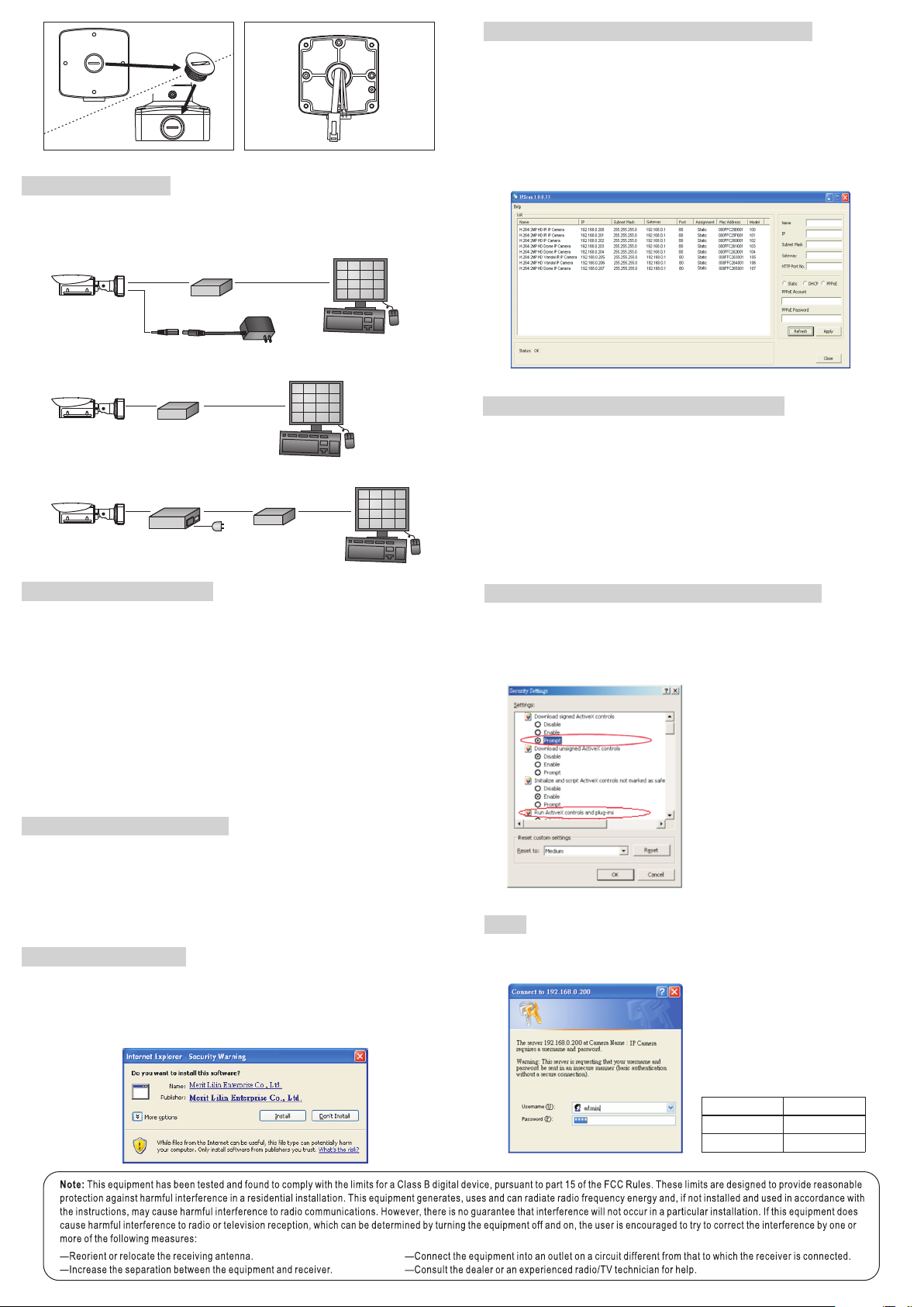
For connecting D/N HD IP Camera series to the network, please follow one of the
system architectures:
(1). Use DC12V power adaptor and network switch connected to a network.
System Architectures
PC
LAN LAN / Internet
Non-PoE Switch
DC12V Adaptor
HD IP CAMERA
FIG.18
PoE Switch
PC
LAN LAN / Internet
(2). Use with PoE of the network switch connected to the network.
HD IP CAMERA
(3). Use PoE power injector and the network switch connected to the network.
PoE Power Injector
PC
LAN LAN / Internet
AC
Non-PoE Switch
LAN
HD IP CAMERA
Before accessing the IP camera, make sure that the camera's RJ-45 network,
audio, and power cables are properly connected. To set the IP address, consult
your network administrator for an available IP address. The default IP address for
each IP camera is 192.168.0.200. Users can use the default IP address for
verifying the camera's network connection.
Before Accessing IP Cameras
Universal ActiveX software components are required for web interface display of
JPEG or Full HD video. When you login to the IP camera by Internet Explorer, the
security warning dialog box will prompt the installation of the Universal ActiveX.
Click Install to download it.
Software Requirements
To change the settings of the IP address, subnet mask, gateway, or HTTP port,
you can follow the steps below:
1. Run the IPScan software.
2. Click Refresh. All available devices should be listed in the device list.
3. Select your device from the list provided.
4. Change the IP address, subnet mask, gateway, or HTTP port for the IP camera.
5. Click Apply to submit the settings.
6. Click Refresh to verify the settings.
Configuring IP Addresses with IPScan Software
To restore the hardware to factory default settings, please follow these steps:
1.Press and hold “RESET Key” for 10 seconds and release.
2.Wait for about 40 seconds, and the network LED light should turn off, and go
back on again.
3.The camera is now restored to factory default settings, and will reboot
automatically.
4.Search for the IP device using the IPScan software.
5.Start the IP device via an Internet browser.
6.Enter the default username “admin” and password “pass” to operate.
For your convenience, the IP address will revert to the default setting
of 192.168.0.200.
NOTE:
Emergency Factory Default
To change an IP address via web interface, type the default IP address
(192.168.0.200) in the Internet browser and follow the steps below:
1. Login to the Full HD IP camera by the default username “admin” and default
password “pass”.
2. Click Basic Mode configuration hyperlink.
3. Click Network->General hyperlink.
4. Change the IP address, subnet mask, gateway, or HTTP port for the IP camera.
5. Click Submit to verify the settings.
Configuring IP Addresses via Web Interface
Make sure your Internet browser allows the signed ActiveX plug-in to work on
your computer. Set “Download Signed ActiveX plug-in controls” to “Prompt”
and “Run ActiveX control and plug-in” to “Enable”. You can set this option via
Internet Explorer-> Tools-> Options-> Security Settings.
Internet Browser Settings & Application Required
Once complete, you can access the IP
camera's live video by entering the
default IP address via your Internet
browser. As the security warning dialog
box appears, click OK to download the
ActiveX directly from the IP camera.
Login
To logon the FULL HD IP camera, please type username and password in
logon HTML page and click on Submit button to enter the system.
The default usernames and
passwords are as follows:
Username admin
Password pass
Administrator
FIG.17

Other Lilin IP Camera manuals

Lilin IPR712S User manual

Lilin

Lilin IPR712S User manual

Lilin H.264 User manual

Lilin

Lilin H.264 User manual

Lilin iMEGAPRO IPR722ES User manual

Lilin

Lilin iMEGAPRO IPR722ES User manual

Lilin AHD701A3.6 User manual

Lilin

Lilin AHD701A3.6 User manual

Lilin IPR414/418ESX3 User manual

Lilin

Lilin IPR414/418ESX3 User manual

Lilin iMEGAPRO IPD2220ES User manual

Lilin

Lilin iMEGAPRO IPD2220ES User manual

Lilin AHD7324AX10 User manual

Lilin

Lilin AHD7324AX10 User manual

Lilin PIH-0364X WN IP User manual

Lilin

Lilin PIH-0364X WN IP User manual

Lilin IRS1308 User manual

Lilin

Lilin IRS1308 User manual

Lilin IPC0122P3 User manual

Lilin

Lilin IPC0122P3 User manual

Lilin FD2452E User manual

Lilin

Lilin FD2452E User manual

Lilin IPR732ES User manual

Lilin

Lilin IPR732ES User manual

Lilin L Series Guide

Lilin

Lilin L Series Guide

Lilin IPG012ES User manual

Lilin

Lilin IPG012ES User manual

Lilin PIH-0364X WN IP User manual

Lilin

Lilin PIH-0364X WN IP User manual

Lilin iMEGALITE series User manual

Lilin

Lilin iMEGALITE series User manual

Lilin UFG1122 Guide

Lilin

Lilin UFG1122 Guide

Lilin AHD DOME User manual

Lilin

Lilin AHD DOME User manual

Lilin IPR454XW User manual

Lilin

Lilin IPR454XW User manual

Lilin IPR614ES4.3 User manual

Lilin

Lilin IPR614ES4.3 User manual

Lilin AHD612AX4.2 User manual

Lilin

Lilin AHD612AX4.2 User manual

Lilin ipg1022esx User manual

Lilin

Lilin ipg1022esx User manual

Lilin UHG1182E User manual

Lilin

Lilin UHG1182E User manual

Lilin 6122 Manual

Lilin

Lilin 6122 Manual

Popular IP Camera manuals by other brands

LEGRAND VADDIO ConferenceSHOT 10 installation guide

LEGRAND

LEGRAND VADDIO ConferenceSHOT 10 installation guide

Honeywell 2450Cm Series Quick installation guide

Honeywell

Honeywell 2450Cm Series Quick installation guide

Prosilica GB660 user manual

Prosilica

Prosilica GB660 user manual

Smartec STC-IPM3542A/1 user manual

Smartec

Smartec STC-IPM3542A/1 user manual

Rear view safety RVS-83112-WiFi product manual

Rear view safety

Rear view safety RVS-83112-WiFi product manual

Marmitek IP EYE ANYWHERE 10 Quick installation guide

Marmitek

Marmitek IP EYE ANYWHERE 10 Quick installation guide

Moxa Technologies VPort 56-2MP Quick installation guide

Moxa Technologies

Moxa Technologies VPort 56-2MP Quick installation guide

D-Link DCS-1000 installation guide

D-Link

D-Link DCS-1000 installation guide

Optiview HDD3MIA user manual

Optiview

Optiview HDD3MIA user manual

D-Link SECURICAM Network DCS-5300G Quick installation guide

D-Link

D-Link SECURICAM Network DCS-5300G Quick installation guide

Moxa Technologies VPort P06-2L25M Quick installation guide

Moxa Technologies

Moxa Technologies VPort P06-2L25M Quick installation guide

Foscam FI8903W Quick installation guide

Foscam

Foscam FI8903W Quick installation guide

Oncam Evolution 05 Installation & user manual

Oncam

Oncam Evolution 05 Installation & user manual

Velleman CAMCOLBUL22N user manual

Velleman

Velleman CAMCOLBUL22N user manual

Digitus DN-16080 Quick installation guide

Digitus

Digitus DN-16080 Quick installation guide

JVC VN-H557U instructions

JVC

JVC VN-H557U instructions

Bosch NDN-498 Brochure & specs

Bosch

Bosch NDN-498 Brochure & specs

Wireless interactive HH9000 Series product manual

Wireless interactive

Wireless interactive HH9000 Series product manual

manuals.online logo
manuals.online logoBrands
  • About & Mission
  • Contact us
  • Privacy Policy
  • Terms and Conditions

Copyright 2025 Manuals.Online. All Rights Reserved.