Lincoln M 16 User manual

2.6A-20004-B96
LINCOLN GmbH Postfach 1263 D-69183 Walldorf Tel +49 (6227) 33-0 Fax +49 (6227) 33-259
Page 1 from 15
Subject to change without notice
Owner Manual
Technical Description
10041327
Printed Circuit Board 236-13870-1
Models : M 16 - M 23
for Metering Device Control (microprocessor control)
Industrial Applications

LINCOLN GmbH Postfach 1263 D-69183 Walldorf Tel +49 (6227) 33-0 Fax +49 (6227) 33-259
Page 2 from 15
Owner Manual
Technical Description
2.6A-20004-B96
Subject to change without notice
Voltage [V]
12/24
12/24
12/24
12/24
24 VDC
24 VDC, 115 VAC,
230 VAC
Control unit
integrated
F *,**
integrated
F*,** V 00-V03
integrated
M 00-M 03***
without control
unit or with
external control
unit*
integrated
F *,**ADR
V 00-V 03*,** ADR
integrated
H*
integrated
H * ADR
external
PSG 01
external
PSG 02
ApplicationsSetting ranges
P : 6 hours, fixed
A : 2 to 30 minutes
P 1 : 3.75 to 56.25 mi-
nutes
P 2: 1 hour to 15 hours
A 1 : 7.5 seconds to
112.5 seconds
A 2 : 2 to 30 minutes
P : 4 to 60 minutes
P : 1 to 15 hours
Ü : 5 or 30 minutes
B : 6 hours, fixed
A: 2 to 30 minutes
B : 6 hours, fixed
A : 2 to 30 minutes
P : 0.5, 1, 2...to 12 hrs
A : 2, 4, 8, 16, 32 min
P : 1 min to 160 hrs
A : 1 min to 160 min
Ü : 1 min to 160 min
Pump
203
203
203
203
203
203
A - Operating time ranges B - Time of availability P - Pause time range Ü - Monitoring time
* 1A1 - Version - Pump without connection for the illuminated pushbutton
**2A1 - Version - Pump with connection for the illuminated pushbutton
***2A4 - Version - Pump with microprocessor control
Note: The applications of the progressive systems are various. There is therefore a corresponding control unit available for
each individual application.
Part no.
236-13856-1
236-13862-1
236-13870-1
236-13859-1
236-13862-1
236-13857-1
236-13857-1
236-13834-1
664-36875-1
236-13860-2
Survey

2.6A-20004-B96
LINCOLN GmbH Postfach 1263 D-69183 Walldorf Tel +49 (6227) 33-0 Fax +49 (6227) 33-259
Page 3 from 15
Subject to change without notice
Owner Manual
Technical Description
Page
Survey.............................................................................. 2
Printed circuit board M 16 - M 23 ............................... 4
Applications ..................................................................... 4
Advantages ...................................................................... 4
Power supply ................................................................... 5
Mode of operation ........................................................... 6
Pause time ................................................................ 7
Operating time ........................................................... 8
Monitoring time ......................................................... 8
Functional check ....................................................... 8
Funktion of the Push ...................................................... 9
To remedy to a fault ....................................................... .9
Further information can be found in the following manuals:
Technical Description Pump Model 203
Technical Description Progressive Metering Devices for
Grease and Oil, model SSV
Technical Description for Electronic Control Units of the
model 203 pump
Printed Circuit Board 236-13856-1, Model F
Printed Circuit Board 236-13862-1, Model V 00-V 03
Printed Circuit Board 236-13857-1, Model H
Printed Circuit Board 236-13870-1, Model M 00 - M 15
Timer 236-13860-2, Model PSG 02
Installation Instructions
Parts Catalog
Table of Contents
Page
Time setting................................................................... 10
Test run /To trigger an additional lubrication ..............11
Repair .............................................................................11
The faults and their causes ....................................... 1 2
Fault indication.............................................................. 12
Troubleshooting ........................................................... 13
Technical data .............................................................. 13
Connection diagram .................................................... 14
Combinations of the jumper positions ...................... 15

LINCOLN GmbH Postfach 1263 D-69183 Walldorf Tel +49 (6227) 33-0 Fax +49 (6227) 33-259
Page 4 from 15
Owner Manual
Technical Description
2.6A-20004-B96
Subject to change without notice
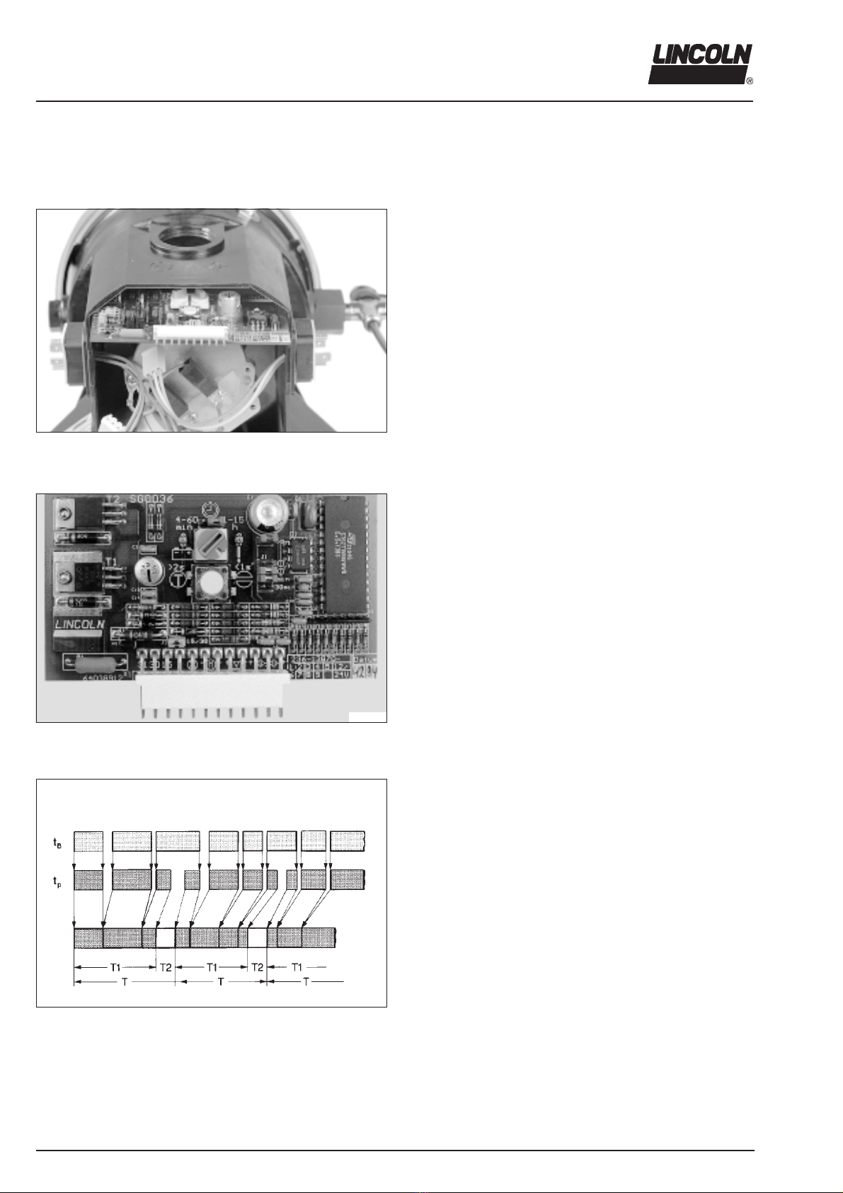
Printed Circuit Board , M 16 - M 23*
Applications
1193b95
Fig. 1 - Supply voltage and machine contact
Possibilities of use
Lubrication cycles
- as a function of the machine operating hours and
-in addition, as a function of add-on units, auxiliairy units, etc.
which temporarily run during the machine operating hours and
must be lubricated only within their running time.
The power supply (+ and - ) is applied (jumper 15/30, Fig. 3, has
been removed). When the machine contact (external contact) is
switched on, the centralized lubrication system is ready for ope-
ration.
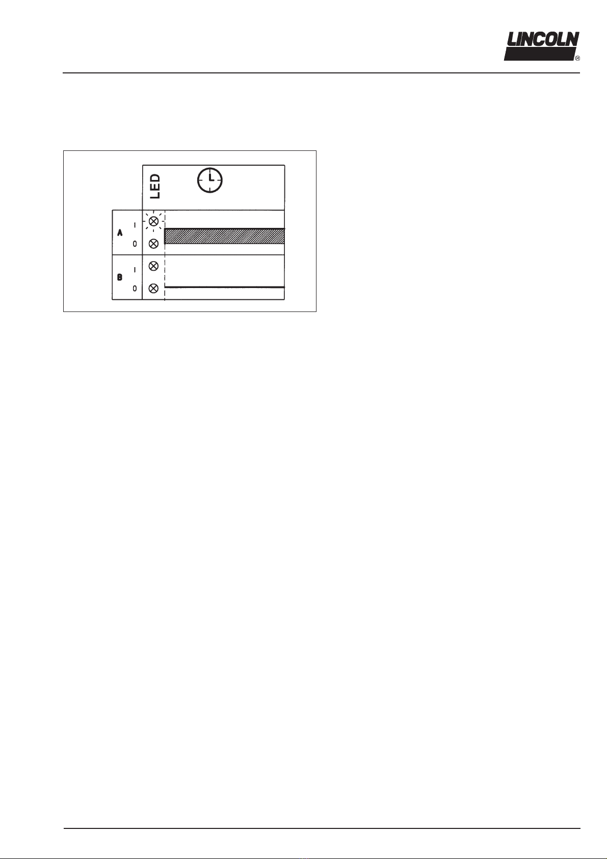
Indication of the time of availability: external relay 1 (Fig.1) has
picked up, LED (Fig.11) is lit.
Advantages
The central lubrication system is monitored, i.e. the readiness for service and faults are indicated (industrial applications
: permanent signal, see LED fig.11).
Note: Applications for commercial vehicles and industrial applications with flashing fault signal : refer to Technical Descrip-
tion of printed circuit board 236-13870-1, models M 00 - M 15
The following functions and operations are monitored and indicated as a fault in the case of a malfuncion.
Pump:
Function of the drive motor
Supply voltage failure - no lubrication
Pump element does not suppply - no lubrication
Reservoir empty (if low-level control not available) - no lubrication
Note: The fault is only indicated when the reservoir is complete-
ly empty and as soon as the pump element stops dispensing
the lubricant.
Reservoir empty (when low-level control available) - The lubricati-
on cycle occurs until the end of the operating time.
Note:The fault is indicated when the reservoir is empty, but if the
pump element is still surrounded with lubricant.
*M 16 - M 23 is the designation of the respective version of the printed circuit board (see Combinations of the jumper
positions, page 15). It is part of the pump type designation code mentioned on the nameplate of each pump.
System:
Lubrication point or metering device blocked
Main line leaking (from pump to the monitored metering device)
Air bubbles in the grease
Lubrication circuit 1 and/or - if any- lubrication circuit 2 mal-
functioning
1 - external relay
2 - machine contact
3 - Push for additional lubrication

2.6A-20004-B96
LINCOLN GmbH Postfach 1263 D-69183 Walldorf Tel +49 (6227) 33-0 Fax +49 (6227) 33-259
Page 5 from 15
Subject to change without notice
Owner Manual
Technical Description
The signal output via an external relay is given as follows:
Permanent signal (D)
Jumper B/D removed
External relay
Is picked up
LED (Fig. 11) is lit perma-
nently
Has dropped out, LED is not
lit, the central lubrica-
tion pump does not start
System
Readiness for service O.K.
(threre is no fault)
Fault
Fig. 2 - Printed circuit board without B/D jumper
Power Supply
The central lubrication pump must be connected to the supply
voltage (+ and - ).
The machine contact (external contact) is used for the activati-
on as a function of auxiliary units or drives, etc.. See Fig. 1.
00002614
00002613
Fig. 3 - Printed circuit board without jumper 15/30

LINCOLN GmbH Postfach 1263 D-69183 Walldorf Tel +49 (6227) 33-0 Fax +49 (6227) 33-259
Page 6 from 15
Owner Manual
Technical Description
2.6A-20004-B96
Subject to change without notice
The printed circuit board
- is integrated in the pump housing.
00002616
Fig. 4 - Printed circuit board installed in the housing
1059a95
A lubrication cycle consists of one pause time and one opera-
ting time. Once the pause time has elapsed, the operating time
starts to run. This lubrication cycle is repeated permanently af-
ter the machine has been put into operation. Refer to Fig.6.
During the operating time the pump element delivers the lubri-
cant to the lubrication points via progressive metering devices.
Fig. 5 - Printed circuit board 236-13870-1
20002441
- automatically controls the sequence of the pause and operating
times of the 203 central lubrication pump as a function of the
machine working hours tB (Fig. 6) and as a function of the ma-
chine contact (external contact).
The sequence of the pause and operating times is activated
when the machine contact is switched on.
Fig.6 - Time sequence diagram
tB - Working hour T - Lubrication cycle
tP - Various pause time T1 -Stored pause times
T2 -Operating times
Mode of Operation

2.6A-20004-B96
LINCOLN GmbH Postfach 1263 D-69183 Walldorf Tel +49 (6227) 33-0 Fax +49 (6227) 33-259
Page 7 from 15
Subject to change without notice
Owner Manual
Technical Description
Two seconds after the supply voltage has been applied the mo-
nitoring output (connection 4 of the 5-wire connector) is activa-
ted.
A relay connected externally (see Fig. 7) picks up and signals
the readiness for service of the 203 lubrication pump.
The LED (Fig. 11) is lit.
In the case of a fault (supply voltage failure, system mal-
functioning) the relay drops out, thus providing a fail-safe mo-
nitoring of the central lubrication pump.
The connected signal lamp is not lit.
Switching on and off the machine contact (auxiliary units, auxi-
liary drives, etc.) has no influence on the function of the monito-
ring output.
The drive motor continues to be monitored.
Output for fault signal/readiness for service
The output for the activation of the external relay (NPN transistor)
is short-circuit proof and overload-proof. The maximum current
switched is 3 A.
1193b95
Pause time
The pause time
- determines the frequency of the lubrication cycles within a wor-
king cycle;
- is started and stopped via the machine contact;
- is adjustable.
When the supply voltage is switched off, the pause times which
have already elapsed as well as the momentary operating con-
ditions (faults) are stored by an electronic memory (EEPROM).
After the supply voltage is switched on again, the printed circuit
board operates from the point where it had been interrupted.
If the setting is modified within the pause time, the printed cir-
cuit board takes over the new value only at the end of the opera-
ting time.
The pause time setting may be different for each application. It
must be adjusted in accordance with the respective lubrication
cycles. Also refer to To set the pause time.
1161b95
Fig. 8 - Sequence of a lubrication cycle
A - Monitoring of the motor
B - Sequence of the operating time
C - Sequence of the monitoring time
D - Readiness for service and fault indication
I - Operating time
P - Pause time
Fig. 7 - Connection diagram
1 - External relay
2 - Machine contact
3 - Pushbutton for additional lubrication

LINCOLN GmbH Postfach 1263 D-69183 Walldorf Tel +49 (6227) 33-0 Fax +49 (6227) 33-259
Page 8 from 15
Owner Manual
Technical Description
2.6A-20004-B96
Subject to change without notice
Operating time
Apiston detector (initiator) which has been installed on a me-
tering device instead of a piston closure plug monitors and
brings the pump operating time to a close after all the pistons
of this metering device have dispensed their lubricant quanti-
ty.
The operating time depends on the systems lubricant requi-
rement and the location of the piston detector (installed either
on the main metering device or on the secondary metering
device).
Note: If two lubrication cycles are monitored, the operating
time ends after the two piston detectors have transmitted their
signal to the printed circuit board.
The operating time alsways completely elapses, even if the
machine contact is switched off.
00002634
Fig. 9 - Piston detector installed on the metering device
10012434
Fig. 11- LED display for the monitoring time or fault indication
Functional check
Each time the machine contact (external contact) is switched
on, a functional check of the drive motor takes place automati-
cally.
During the functional check the motor is switched on for 0.1
second (the stirring paddle slightly rotates).
If there is a fault, the LED is not lit and the pump stops ope-
rating. See Fault indication.
20002459
Fig. 10- Monitoring ranges
1 - Jumper for monitoring time
5 min 5 minutes
30 min 30 minutes
2 - Jumper for 1 circuits 1 O
or 2 circuits 2 O
Monitoring time
A fixed monitoring time of max. 5 or 30 minutes (depending
on the jumper position) runs in parallel to the operating time.
Note: Normally, the monitoring time ends at the same time as
the operating time.
If there is no switching off signal from the piston detector to
the printed circuit board within 5 or 30 minutes, a fault signal
will occur.
The LED (Fig. 11) is extinguished and the pump stops ope-
rating.
If the operating time exceeds 5 minutes, the monitoring time
can be changed from 5 to 30 minutes by replugging the jum-
per.
If there are two monitored lubrication cycles, the jumper
must be plugged to (2 O).

2.6A-20004-B96
LINCOLN GmbH Postfach 1263 D-69183 Walldorf Tel +49 (6227) 33-0 Fax +49 (6227) 33-259
Page 9 from 15
Subject to change without notice
Owner Manual
Technical Description
Pushbutton
The following can be performed with the pushbutton (item 4,
Fig. 16):
- triggering an additional lubrication cycle - Press pushbutton for
over 2 seconds (> 2 s)
- in the case of a fault, switch on pump again by pressing push-
button (> 2 seconds)
LED display
The LED display indicates the operating state of the centralized
lubrication system.
The operating states may be:
- LED is lit permanently ............................................ System o.k.
- LED is not lit ...................................................... There is a fault
Fig. 12 - Indicated operating states
A - Indication of function
B - Fault indication
1162b95
Functions of the Pushbutton and LED Display
To Remedy to a Fault
Important: If there has been any fault, the pump will not start
automatically after the elimination of that fault. It must be swit-
ched on, i.e. an additional lubrication cycle must be triggered.
See item To trigger an additional lubrication cycle.
* In the case of a fault, check whether the central lubrication
pump and the connected system are malfunctioning.
* Eliminate the cause of the fault. Refer to The faults and their
causes.
* Switch the pump on again by triggering an additional lubrica-
tion cycle. For this, press the pushbutton (4, Fig. 16) >2 se-
conds.
Once the fault is eliminated, the LED will be lit again at the
end of the lubrication cycle.

LINCOLN GmbH Postfach 1263 D-69183 Walldorf Tel +49 (6227) 33-0 Fax +49 (6227) 33-259
Page 10 from 15
Owner Manual
Technical Description
2.6A-20004-B96
Subject to change without notice
* To set the pause time, remove the cover on the pump hou-
sing.
Note: To reset or remove a jumper, remove the printed circuit
board.
Important: After having set the pause time, screw the cover on
the pumphousing again.
00002617
Fig. 13 - The cover to access the printed circuir board has been removed
Switch position 1 2 3456789ABCDEF
Minutes 4 8 12 16 20 24 28 32 36 40 44 48 52 56 60
Hours 1 2345678 9101112131415
Fig. 14 - Rotary switch - Pause time
20002454
To set the pause time
The pause time can be adjusted to 15 different settings by means
of the blue rotary switch.
Time ranges: Minutes or hours
Time Setting

2.6A-20004-B96
LINCOLN GmbH Postfach 1263 D-69183 Walldorf Tel +49 (6227) 33-0 Fax +49 (6227) 33-259
Page 11 from 15
Subject to change without notice
Owner Manual
Technical Description
If the printed circuit board must be replaced, a model M 00 will
always be delivered. See chart page 15.
Before installing another printed circuit board, take care that
the jumper is set to the same position as on the old printed
circuit board.
To check the function of the pump it is possible to perform an
operational test.
* Switch on the power supply
* Switch on the machine contact
To check whether power is applied to the printed circuit board,
observe whether the left-hand LED 1, Fig. 16, is lit.
Press the pushbutton (> 2 seconds) for triggering an additional
lubrication (pushbutton on the printed circuit board or pushbut-
ton on the switch cabinet) until the pump starts.
A shorter pause time elapsed, followed by a normal lubrication
cycle.
The right-hand LED shows the following functions:
- Operation (LED is lit)
- Faults (LED extinguished)
Additional lubrication cycles can be triggered at any time
10012426
Fig. 16 - LED of the printed circuit board
1 - LED, left-hand 3 - LED, right-hand,
Power supply Indication of operation
2 - Rotary switch 4 - Pushbutton for
pause time additional lubrication cycle
Operational Test /To Trigger an Additional Lubrication Cycle
20002448
Fig. 15 - Preselection of the time ranges
Repair
The defective printed circuit boards should be suitably packed
and returned to the factory.
Factory setting
Note: The 0 position corresponds to the shortest time.
The time ranges (hours or minutes) can be changed by replug-
ging the jumper on the printed circuit board (Fig. 15).
Pause time
Rotary switch on .............................................................. 6 hours
or ................................................................................. 24 minutes
Refer to the chart page 15 for the jumper factory setting. The
combination number can be learnt from the pump type designa-
tion code mentioned on the nameplate of each pump.

LINCOLN GmbH Postfach 1263 D-69183 Walldorf Tel +49 (6227) 33-0 Fax +49 (6227) 33-259
Page 12 from 15
Owner Manual
Technical Description
2.6A-20004-B96
Subject to change without notice
The Faults and their Causes
If any the following faults occurs, the LED is extinguished, the
external relay drops out and the pump stops operating.
Faults
Drive motor defective
- The external relay drops out, the LED is extinguished after 2
seconds
Malfunctions
such as
- blocked lubrication point (s)
- blocked metering devices (s)
- interruption in the main line leading to the metering device
equipped with a piston detector
- air in system
- reservoir empty
-are not indicated as individual faults.
In the case of a malfunction the piston detector (initiator) can
no longer record the piston movements and, therefore, it
cannot switch off the pump.
Due to the monitoring time which runs in parallel to the opera-
ting time, the printed circuit board switches off the pump at the
end of the monitoring time
The external relay drops out, the LED is extinguished.
The pump no longer starts automatically. See To Remedy to
a Fault.
Reservoir empty in the case the pump is equipped with a low-
level control.
The LED is extinguished. The operating time comes to a clo-
se.
The pump no longer starts automatically. See To Remedy to
a Fault.
Fault Indication
1162b95
Fig. 17 - Readiness for service and fault indication
A - Readiness for service
B - Fault indication

2.6A-20004-B96
LINCOLN GmbH Postfach 1263 D-69183 Walldorf Tel +49 (6227) 33-0 Fax +49 (6227) 33-259
Page 13 from 15
Subject to change without notice
Owner Manual
Technical Description
Note: The pump operation can be checked from the outside by
observing whether the stirring paddle is rotating (e.g. by trigge-
ring an additional lubrication), whether the LED on the printed
circuit board are lit or whether the external relay has picked up.
Cause:
Voltage supply interrupted
Voltage supply to the printed-circuit interrupted
Printed circuit board defective
Remedy:
Check the voltage supply to the pump. If necessary, correct
the cause of the fault.
Check the line leading from the pump plug to the printed cir-
cuit board.
If the voltage is applied, the left-hand LED is lit.
Replace the printed circuit board.
Fault: The pump motor does not run
Cause:
Piston detector (initiator) defective.
Cable connection of the piston detector to the pump interrup-
ted
Printed circuit board defective
Remedy:
Disconnect the main line leading to the monitored metering
device.
Unscrew the piston detector and check it. For this, insert a
metallic pin into the borehole of the detector. Let it there over
2 seconds and then remove it. If the pump is not switched off
afterwards, check the cable conections to the pump. If neces-
sary, replace the piston detector with the connector.
Check the cable connections to the pump. If necessary, repla-
ce the piston detector with the connector.
Replace the printed circuit board
Fault: The pump motor supplies permanently (5 minutes or 30 minutes )- Duration of the monitoring time
The printed circuit boards model M comply with the EMC guide-
line 89 / 336 / EWG
Emitted interference acc. to .................... EN 55011 / 03.91 and
......................................................... EN 50081-1 / 01.92
Noise immunity acc. to .............................. prEN 50082-2 / 1993
Time Setting
Pause time, acc.to jumper position:
...................................................4, 8, 12,...to 60 minutes
......................................................... 1, 2, 3...to 15 hours
The operating time is switched off via the piston detector.
Factory setting
Pause time ........................................................... 6 hours
or .................................................................... 24 minutes
Monitoring time ................................................ 5 minutes
or .................................................................... 30 minutes
Rated voltage ............................................................ 12/24V DC
Operating voltage
12V/ 24V .......................................................... 9V to 30V
Residual rippple in relation
with the operating voltage .................... ± 5% acc. to DIN 41755
Motor output ............................. transistor 7A/short-circuit proof
Reverse voltage protection:
The operating voltage inputs are protected against
polarity reversal
Temperature range: .................................. -25°C to 70°C
Output fault/readiness for operation
transistor 3A/short-circuit proof
Protection
Printed circuit board installed in housing ..................... IP 6K 9K
In order to protect the printed circuit board against condensati-
on, it is covered with a protective varnish.
Technical Data
Troubleshooting

LINCOLN GmbH Postfach 1263 D-69183 Walldorf Tel +49 (6227) 33-0 Fax +49 (6227) 33-259
Page 14 from 15
Owner Manual
Technical Description
2.6A-20004-B96
Subject to change without notice
20002460
Fig. 19 - Terminals of the printed circuit board
Fig. 18 - Connection diagram QUICKLUB 203 with monitoring of the metering devices (Industry)
Connectors AMP, type Superseal
A - Printed circuit board
B - Pump housing
C - Cable connector 1
D - Line socket 1
with connection cable, 5-wire
E - Cable, brown
F - Cable, yellow
G - Cable, white
H - Cable, red
I - Cable, black
J - Pushbutton for additional lubrication
K - Machine contact
L - Relay
N - Cable connector 2
O - Line socket 2 with
1 or 2 connection cables
2-wire
P - Cable, blue
Q - Cable, brown
R - Piston detector (initiator)
Monitored circuit 1
1194a95
30 -
Battery voltage
-
Low-level control
31 -
Earth
15 -
Machine contact
Z-
Additional lubrication
M
- Motor -
Signal lamp
1
-
Lubrication circuit 1 2
-
Lubrication circuit 2
Connection Diagram

2.6A-20004-B96
LINCOLN GmbH Postfach 1263 D-69183 Walldorf Tel +49 (6227) 33-0 Fax +49 (6227) 33-259
Page 15 from 15
Subject to change without notice
Owner Manual
Technical Description
Combinations of the jumper positions - Survey
4 - 601 - 15 30521
X
X
X
X
X
X
X
X
X
X
X
X
X
X
X
X
X
X
X
X
X
X
X
X
X
X
X
X
X
X
X
X
X
X
X
X
X
X
X
X
X
X
X
X
X
X
X
X
X
X
X
X
X
X
X
X
X
X
X
X
X
X
X
X
X
X
X
X
X
X
X
X
X
X
X
X
X
X
X
X
X
X
X
X
X
X
X
X
X
X
X
X
X
X
X
X
X
X
X
X
X
X
X
X
X
X
X
X
X
X
X
X
X
X
X
X
X
X
X
X
Possibilities of
preselection
Setting
Jumper position
Kombination Nr.
M 00
M 01
M 02
M 03
M 04
M 05
M 06
M 07
M 08
M 09
M 10
M 11
M 12
M 13
M 14
M 15
M 16
M 17
M 18
M 19
M 20
M 21
M 22
M 23
1188a95
terminal
15;30
only
terminal
15
perma-
nent
intermit-
tent
Connection of the
supply voltage
Signal indication
in the case of
faults
Signal output
Pause time
ranges
h min
Monitoring time
ranges
(min)
Number of the
monitored lubri-
cation circuits
This manual suits for next models
1
Table of contents
Other Lincoln Industrial Equipment manuals

Lincoln
Lincoln SKF VP Series User manual

Lincoln
Lincoln 84700 Owner's manual

Lincoln
Lincoln SKF Minilube User manual

Lincoln
Lincoln SKF SMBM-X User manual

Lincoln
Lincoln 85250 Owner's manual

Lincoln
Lincoln SKF VectoLub VE1B unit User manual

Lincoln
Lincoln Quicklub SSV User manual

Lincoln
Lincoln Quicklub SSV User manual

Lincoln
Lincoln SKF DigitalSuper UFD10 Series User manual

Lincoln
Lincoln Impinger 1100 Series User manual