Lincoln SKF Minilube User manual

Assembly Instructions
SKF Minilube
Date:
16.6.2022
Document no.:
MINILUBE
Version: 2C
Read this manual before
installing or commissioning
the product and keep it at
hand for later reference!

2
Original EC Declaration of Incorporation in accordance with Directive 2006/42/EC,
Appendix II Part 1 B
The manufacturer hereby declares at its sole responsibility that the partly completed machinery conforms to the essential health and safety
requirements of the Machinery Directive 2006/42/EC, Annex I, marked in the Annex to the EC Declaration of Incorporation as applicable and
fulfilled at the time of placing on the market.
The special technical documents were prepared following Annex VII part B. Upon justifiable request, these special technical documents can be
forwarded electronically to the respective national authorities. The authorized company for the compilation of the technical documentation is the
manufacturer.
Designation:
Electrically driven pump to supply lubricant during intermittent operation within a centralized lubrication system
Type
MINILUBE-170-24; MINILUBE-170-12; MINILUBE-170-ST102-12V, MINILUBE-170-ST102-24V, MINILUBE-170LS-
ST102-12V & MINILUBE-170LS-ST102-24V
Furthermore, the following directives and standards were applied in the respective applicable areas:
2011/65/EU: ROHS II including the addition (EU) 2015/863
2014/30/EU: Electromagnetic Compatibility (Industry)
EN ISO 12100:2010
EN 61000-6-2:2005/AC:2005
EN 61000-6-4:2007/A1:2011
EN IEC 63000:2018
The partly completed machinery must not be put into service until it has been established that the machinery into which it is to be incorporated is
in compliance with the provisions of the Machinery Directive 2006/42/EC and all other applicable Directives.
Muurame, 16.12.2020
Juha Kärkkäinen
Design Office Manager
SKF Lubrication Management
Manufacturer: Oy SKF Ab Finland Teollisuustie 6 40951 Muurame FINLAND
Original UK Declaration of incorporation according to the Supply of Machinery (Safety)
Regulations 2008 No. 1597 Annex II
The manufacturer hereby declares under sole responsibility that the partly completed machinery complies with the essential health and safety
requirements of UK legislation Supply of Machinery (Safety) Regulations 2008 No. 1597Annex I, marked in the Annex to the EC Declaration of
Incorporation as applicable and fulfilled at the time of placing on the market.
The special technical documents were prepared following Annex VII part B. Upon justifiable request, these special technical documents can be
forwarded electronically to the respective national authorities. The authorized company for the compilation of the technical documentation is
SKF (U.K.) Limited, 2 Canada Close, Banbury, Oxfordshire, OX16 2RT, GBR.
Designation:
Electrically driven pump to supply lubricant during intermittent operation within a centralized lubrication system
Type
MINILUBE-170-24; MINILUBE-170-12; MINILUBE-170-ST102-12V, MINILUBE-170-ST102-24V, MINILUBE-170LS-
ST102-12V & MINILUBE-170LS-ST102-24V
Furthermore, the following regulations and standards were applied in the respective applicable areas:
"Ordinance on the restriction of use of certain hazardous substances in Electrical and Electronic Equipment 2012 No. 3032
"Electromagnetic compatibility Ordinance 2016 No. 1091
EN ISO 12100:2010
EN 61000-6-2:2005/AC:2005
EN 61000-6-4:2007/A1:2011
EN IEC 63000:2018
The partly completed machinery must not be put into service until it has been established that the machinery into which it is to be incorporated is
in compliance with the provisions of UK legislation Supply of Machinery (Safety) Regulations 2008 No. 1597 and all other applicable Directives.
Muurame, 5.10.2021
Juha Kärkkäinen
Design Office Manager
SKF Lubrication Management
Manufacturer: Oy SKF Ab Finland Teollisuustie 6 40951 Muurame FINLAND

3
Appendix to Declaration of Incorporation in accordance with 2006/42/EC, Annex II, No. 1 B
Description of the essential health and safety requirements according to 2006/42/EC, Annex I, which have been applied and
fulfilled. Any essential health and safety requirements not listed here are not relevant to this product
Table 1
Appendix to Declaration of Incorporation
Valid for: MINILUBE lubrication pumps
No.:
Essential health and safety requirement
Applicable:
Fulfilled:
1.1.1
Definitions
Yes
Yes
1.1.2
Principles of safety integration
Yes
Yes
1.1.3
Materials and products
Yes
Partially1)
1.1.5
Design of machinery to facilitate its handling
Yes
Yes
1.2
Control systems
Yes
Yes
1.2.1
Safety and reliability of control systems
Yes
Yes
1.2.2
Control devices
Yes
Yes
1.3
Protection against mechanical hazards
Yes
Yes
1.3.4
Risks due to surfaces, edges or angles
Yes
Yes
1.6
Maintenance
1.6.1
Machinery maintenance
Yes
Yes
1.6.4
Operator interventions
Yes
Yes
1.7
Information
Yes
Yes
1.7.1
Information and warnings on the machinery
Yes
Yes
1.7.2
Warning of residual risks
Yes
Yes
1.7.3
Marking of machinery
Yes
Yes
1.7.4
Instructions
Yes
Yes
1) Not completely fulfilled: Hazards due to the lubricant used must be assessed by the operator on the basis of the Safety
Data Sheet (SDS) and, if necessary, protective measures must be taken.

4
Masthead
Manufacturer
Oy SKF Ab
Teollisuustie 6 P.O Box 80
40951 Muurame, Finland
www.skf.com/lubrication
Authorized local distributors
- Great Britain -
SKF (U.K.) Limited,
2 Canada Close, Banbury, Oxfordshire,
OX16 2RT, GBR.
- North America -
SKF Lubrication Business Unit
Lincoln Industrial
5148 North Hanley Road, St. Louis,
MO. 63134 USA
- South America -
SKF Argentina Pte. Roca 4145,
CP 2001 Rosario, Santa Fe
Warranty
The instructions contain no statements regarding the warranty or liability for defects. That information can be found in our
General Terms of Payment and Delivery.
Training
We conduct detailed training in order to enable maximum safety and efficiency. We recommend taking advantage of this
training. For further information, contact your authorized SKF dealer or the manufacturer.

5
Table of contents
Masthead........................................................................................................................................................................................ 4
Table of contents ............................................................................................................................................................................ 5
Safety alerts, visual presentation, and layout ................................................................................................................................. 7
1. Safety instructions ...................................................................................................................................................................... 8
General safety instructions ....................................................................................................................................................8
General electrical safety instructions ..................................................................................................................................... 8
General behaviour when handling the product ...................................................................................................................... 8
Intended use.......................................................................................................................................................................... 8
Persons authorized to use the product .................................................................................................................................. 9
Foreseeable misuse .............................................................................................................................................................. 9
Referenced documents ......................................................................................................................................................... 9
Prohibition of certain activities ...............................................................................................................................................9
Painting plastic components and seals.................................................................................................................................. 9
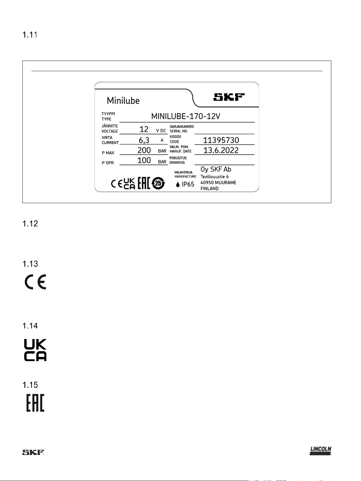
Safety markings on the product ...........................................................................................................................................9
Notes on the type plate...................................................................................................................................................... 10
Note on Low Voltage Directive ............................................................................................ Error! Bookmark not defined.
Note on Pressure Equipment Directive.............................................................................................................................. 10
Notes on CE marking ........................................................................................................................................................ 10
Notes related to the UKCA marking................................................................................................................................... 10
Notes on EAC mark........................................................................................................................................................... 10
Note on China RoHS mark ................................................................................................................................................ 11
Emergency shutdown ........................................................................................................................................................ 11
Assembly, maintenance, fault, repair................................................................................................................................. 11
First start-up, daily start-up................................................................................................................................................ 11
Residual risks .................................................................................................................................................................... 12
2. Lubricants ................................................................................................................................................................................. 13
General information ............................................................................................................................................................. 13
Material compatibility ........................................................................................................................................................... 13
Temperature properties ....................................................................................................................................................... 13
Aging of lubricants ............................................................................................................................................................... 13
Avoidance of faults and hazards.......................................................................................................................................... 13
Solid lubricants .................................................................................................................................................................... 13
3. Overview, design & operation................................................................................................................................................... 14
Main components ................................................................................................................................................................ 14
System diagram, SKF Minilube with internal ST104 control ................................................................................................ 15
System diagram, SKF Minilube with external ST102 control ............................................................................................... 16
4. MINILUBE WITH INTERNAL ST104 CONTROL...................................................................................................................... 17
LEDs.................................................................................................................................................................................... 17
Jumpers............................................................................................................................................................................... 18
Lubrication cycle settings, rotary switch T ........................................................................................................................... 19
Lubrication Cycle Schedule 1, Jumper A Open ......................................................................................................................... 19
Lubrication Cycle Schedule 2, Jumper A Closed....................................................................................................................... 19
Test button S ....................................................................................................................................................................... 20
Power failure........................................................................................................................................................................ 20
Electrical connections 3pump models with internal ST104 control ..................................................................................... 20
4.6.1 Supply voltage connection......................................................................................................................................... 20
4.6.2 Alarm output .............................................................................................................................................................. 21
4.6.3 Interlock input ............................................................................................................................................................ 21
4.6.4 Wiring diagram .......................................................................................................................................................... 21
5. Technical data .......................................................................................................................................................................... 22
Technical specification ........................................................................................................................................................ 22
Designation and order codes............................................................................................................................................... 22
6. Delivery, returns, storage.......................................................................................................................................................... 23
Delivery ............................................................................................................................................................................... 23
Return shipment .................................................................................................................................................................. 23
Storage................................................................................................................................................................................ 23
Storage temperature range ................................................................................................................................................. 23
Storage conditions for products filled with lubricant............................................................................................................. 23
6.5.1 Storage period up to 6 months .................................................................................................................................. 23

6
6.5.2 Storage period between 6 and 18 months .................................................................................................................24
6.5.3 Storage period more than 18 months.........................................................................................................................24
7. Installation and dimensions.......................................................................................................................................................24
General information .............................................................................................................................................................24
Mounting ..............................................................................................................................................................................25
Dimensions ..........................................................................................................................................................................26
8. First start-up..............................................................................................................................................................................27
Inspections prior to initial start-up ........................................................................................................................................27
Inspections during initial start-up..........................................................................................................................................27
Operation .............................................................................................................................................................................28
Filling and draining the pumping unit lubricant reservoir ......................................................................................................28
8.4.1 Using the filling device (SKF code 11600330 and NLGI2 11600340) ........................................................................28
8.4.2 Draining the reservoir.................................................................................................................................................30
Bleeding the pumping unit....................................................................................................................................................31
9. Maintenance and repair ............................................................................................................................................................32
Maintenance ........................................................................................................................................................................32
Periodic inspections .............................................................................................................................................................32
Doser operation inspection ..................................................................................................................................................32
9.3.1 B dosers.....................................................................................................................................................................32
10. Cleaning..................................................................................................................................................................................33
Basics ................................................................................................................................................................................33
Interior cleaning .................................................................................................................................................................33
Exterior cleaning ................................................................................................................................................................33
Cleaning the filter of the filling connection..........................................................................................................................34
11. Faults, causes, and remedies .................................................................................................................................................36
System troubleshooting ST104 control centre ...................................................................................................................36
11.1.1 Control unit does not work .......................................................................................................................................36
11.1.2 All the lubrication points get too little or too much lubricant. ....................................................................................37
11.1.3 Insufficient or no lubricant at the lubrication point. ...................................................................................................37
11.1.4 Overgreasing at the lubrication point .......................................................................................................................37
12. Repairs....................................................................................................................................................................................37
Changing the pumping element .........................................................................................................................................38
Changing of line valve..........................................................................................................Error! Bookmark not defined.
13. Shutdown, disposal .................................................................................................................................................................43
Temporary shutdown .........................................................................................................................................................43
Permanent shutdown, disassembly ...................................................................................................................................43
Disposal .............................................................................................................................................................................43
14. SPARE PARTS.......................................................................................................................................................................43
Minilube with internal ST104 control, spare parts ..............................................................................................................44
Minilube-170-ST102 pumping unit, spare parts .................................................................................................................45
15. SKF MINILUBE WITH ST102 CONTROL CENTRE ...............................................................................................................46
16. Appendix .................................................................................................................................................................................47
China RoHS Table .............................................................................................................................................................47

7
Safety alerts, visual presentation, and layout
While reading these instructions, you will encounter various symbols, illustrations, and text layouts intended to help you navigate
and understand the instructions. Their meaning is explained below.
Safety alerts:
Activities that present specific hazards (to life and limb or possible damage to property) are indicated by safety alerts. Always be
sure to follow the instructions given in the safety alerts.
<
DANGER
These safety alerts indicate an imminent danger. Ignoring them will result in death or serious injury
<
WARNING
These safety alerts indicate potentially imminent danger. Ignoring them could result in death or
serious injury
<
CAUTION
These safety alerts indicate potentially imminent danger. Ignoring them could result in minor injury
<
NOTICE
These safety alerts indicate a potentially harmful situation. Ignoring them could result in damage to
property or malfunctions
Illustrations:
The illustrations used depict a specific product. For other products, they may have the function of a diagram only. This does not
alter the basic workings and operation of the product.
Text layout:
First-order bulleted lists: Items on a bulleted list start with a solid black dot and an indent.
Second-order bulleted lists: If there is a further listing of subitems, the second-order bulleted list is used.
1 Legend: A legend explains the numbered contents of an illustration, presented as a numbered list. Items in a legend start with
a number (with no dot) and an indent.
Second-order legend: In some cases, the numbered contents of an image represent more than just one object. A second-
order legend is then used.
1.Instruction steps: These indicate a chronological sequence of instruction steps. The numbers of the steps are in bold and
Second-order instruction steps: In some cases, it is necessary to divide up a step into a few sub steps. A sequence of
second-order instruction steps is then used.

8
1. Safety instructions
General safety instructions
Putting the products into operation or operating them without having read the instructions is prohibited. The operator must
ensure that the instructions are read and understood by all persons tasked with working on the product or who supervise or
instruct such persons. Retain the instructions for further use.
The product may only be used in awareness of the potential dangers, in proper technical condition, and according to the
information in this manual.
Any faults that could affect safety must be remedied according to responsibility. The supervisor must be notified immediately
in case of malfunctions outside one's individual scope of responsibility.
Unauthorized modifications and changes can have an unpredictable effect on safety and operation. Unauthorized
modifications and changes are therefore prohibited. Only original SKF spare parts and SKF accessories may be used.
Any unclear points regarding proper condition or correct assembly/operation must be clarified. Operation is prohibited until
issues have been clarified.
The components used must be suitable for the intended use and the applicable operating conditions, e.g. max. operating
pressure and ambient temperature range, and must not be subjected to torsion, shear, or bending.
General electrical safety instructions
Electrical devices must be kept in proper condition. This must be ensured by periodic inspections in accordance with the
relevant applicable standards and technical rules. The type, frequency, and scope of the inspections must be determined in
accordance with the risk assessment to be carried out by the operator. Work on electrical components may be performed only
by qualified electricians. Connect the electrical power only in accordance with the valid terminal diagram and in observance of
the relevant regulations and the local electrical supply conditions.
Work on electrical components may be performed only in a voltage-free state and using tools suitable for electrical work. Do
not touch cables or electrical components with wet or moist hands.
Fuses must not be bridged. Always replace defective fuses with fuses of the same type.
Ensure proper connection of the protective conductor for products with protection class I. Observe the specified enclosure
rating.
The operator must implement appropriate measures to protect vulnerable electrical devices from the effects of lightning during
use. The electrical device is not furnished with a grounding system for the dissipation of the respective electric charge and
does not have the voltage strength necessary to withstand the effects of lightning.
General behaviour when handling the product
Familiarize yourself with the functions and operation of the product. The specified assembly and operating steps and their
sequences must be observed.
Keep unauthorized persons away.
Wear personal protective equipment always.
Precautionary operational measures and instructions for the respective work must be observed.
In addition to these Instructions, general statutory regulations for accident prevention and environmental protection must be
observed.
Precautionary operational measures and instructions for the respective work must be observed. Uncertainty seriously
endangers safety.
Safety-related protective and safety equipment must not be removed, modified or affected otherwise in its function and is to be
checked at regular intervals for completeness and function.
If protective and safety equipment has to be dismantled, it must be reassembled immediately after finishing the work, and then
checked for correct function.
Remedy occurring faults in the frame of responsibilities. Immediately inform your superior in the case of faults beyond your
competence.
Never use parts of the centralized lubrication system or of the machine as standing or climbing aids.
Intended use
Supply of lubricants.
The product is intended solely for installation in another machine.
Use is only permitted within the scope of commercial or economic activity by professional users, in compliance with the
specifications, technical data, and limits specified in this manual.

9
Persons authorized to use the product
Operator
A person who is qualified by training, knowledge and experience to carry out the functions and activities related to normal
operation. This includes avoiding possible hazards that may arise during operation.
Specialist in mechanics
Person with appropriate professional education, knowledge and experience to detect and avoid the hazards that may arise
during transport, installation, start-up, operation, maintenance, repair and disassembly.
Specialist in electrics
Person with appropriate professional education, knowledge and experience to detect and avoid the hazards that may arise from
electricity.
Foreseeable misuse
Any usage of the product other than as specified in this manual is strictly prohibited. Particularly prohibited are:
Use of non-specified consumables, contaminated lubricants, or lubricants with air inclusions.
Use of C3 versions in areas with aggressive, corrosive substances (e.g., high salt load).
Use of plastic parts in areas with high exposure to ozone, UV light, or ionizing radiation.
Use to supply, convey, or store hazardous substances and mixtures as defined in the CLP Regulation (EC 1272/2008) or
GHS with acute oral, dermal, or inhalation toxicity or substances and mixtures that are marked with hazard pictograms
GHS01-GHS06 and GHS08.
Use to supply, convey, or store Group 1 fluids classified as hazards as defined in the Pressure Equipment Directive
(2014/68/EU) Article 13 (1) a).
Use to supply, convey, or store gases, liquefied gases, dissolved gases, vapors, or fluids whose vapor pressure exceeds
normal atmospheric pressure (1013 mbar) by more than 0.5 bar at their maximum permissible operating temperature.
Use in an explosion protection zone.
Use without proper securing against excessively high pressures, in the case of pressurized products.
Use outside of the technical data and limits specified in this manual.
Referenced documents
In addition to this manual, the following documents must be observed by the respective target group:
Company instructions and approval rules
If applicable:
Safety data sheet of the lubricant used
Project planning documents
Supplementary information regarding special designs of the pump. This you will find in the special system documentation.
Instructions for other components for setting up the centralized lubrication system.
Prohibition of certain activities
Replacement of or modifications to the pistons of the pump elements
Repairs or modifications to the drive
Painting plastic components and seals
The painting of any plastic components and seals of the products described is prohibited. Completely mask or remove plastic
components before painting the main machine.
Safety markings on the product
NOTE
Further to the findings of the workplace risk evaluation the operating company has to attach additional markings (e. g.
warnings, signs giving orders, prohibition signs or labelling as specified by CLP / GHS), where appropriate.

10
Notes on the type plate
The type plate provides important data such as the type designation, order number, and sometimes regulatory characteristics.
To avoid loss of this data in case the type plate becomes illegible, it should be entered in the manual.
Fig. 1
Type identification plate
Note on Pressure Equipment Directive
Due to its performance characteristics, the product does not reach the limit values defined in Article 4, Paragraph 1,
Subparagraph (a) (ii) and is excluded from the scope of Pressure Equipment Directive 2014/68/EU in accordance with Article 1,
Paragraph 2 Subparagraph (f).
Notes on CE marking
CE marking is effected following the
requirements of the applied directives
requiring a CE marking:
2014/30/EC Electromagnetic Compatibility
2011/65/EU Directive on the restriction of the use of certain hazardous substances in electrical and electronic equipment
(RoHS II)
Notes related to the UKCA marking
The UKCA conformity marking con-
the applicable legal provisions of
Great Britain.
Notes on EAC mark
The EAC conformity marking con-
the applicable legal provisions of the
Eurasian customs union.

11
Note on China RoHS mark
The China RoHS marking confirms that there
is no danger to persons or the environment
from the regulated substances contained
within the intended period of use (number in
the circle) of the product.
Emergency shutdown
This is done by a course of action to be defined by the operator.
Assembly, maintenance, fault, repair
Prior to the start of this work, all relevant persons must be notified of it. At a minimum, the following safety measures must be
taken before any work is done:
Unauthorized persons must be kept away
Mark and secure the work area
Cover adjacent live parts
Dry any wet, slippery surfaces or cover them appropriately
Cover hot or cold surfaces appropriately
Where applicable:
Depressurize
Isolate, lock and tag out
Check to ensure live voltage is no longer present
Ground and short-circuit
The product should be protected as much as possible from humidity, dust, and vibration, and should be installed so that it is
easily accessible. Ensure an adequate distance from sources of heat or cold. Any visual monitoring devices present, such as
pressure gauges, min./max. markings, or oil level gauges must be clearly visible. Observe the mounting position requirements.
Drill required holes only on non-critical, non-load-bearing parts of the operator's infrastructure. Use existing holes where
possible. Avoid chafe points. Immobilize any moving or detached parts during the work. Adhere to the specified torques.
If guards or safety devices need to be removed, they must be reinstalled immediately following conclusion of work and then
checked for proper function.
Check new parts for compliance with the intended use before using them.
Avoid mixing up or incorrectly assembling disassembled parts. Label parts. Clean any dirty parts.
First start-up, daily start-up
Ensure that:
All safety devices are fully present and functional
All connections are properly connected
All parts are correctly installed
All warning labels on the product are fully present, visible, and undamaged

12
Residual risks
Table 2
Residual risks
Residual risk
Possible in life cycle
Prevention/ remedy
Personal injury/ material damage
due to falling of raised parts
A
B
C
G
H
K
Keep unauthorized persons away. No people may
remain under suspended loads. Lift parts with
adequate lifting devices.
Personal injury/ material damage
due to tilting or falling of the product
because of non-observance of the
stated tightening torques
B
C
G
Observe the specified tightening torques. Fix the
product to components with adequate load-bearing
capacities only. If no tightening torques are stated,
apply tightening torques according to the screw
size characteristics for 8.8 screws.
Personal injury/ damage to material
due to spilled or leaked lubricant
B
C
D
F
G
H
K
Be careful when connecting or disconnecting
lubricant feed lines. Always use suitable hydraulic
screw connections and lubrication lines for the
stated pressures. Do not mount lubrication lines to
moving parts or friction points. If this cannot be
avoided, use spring coils respectively protective
conduits.
Fire hazard or damage to the pump
due to an operation with defective
electrical components, e.g.
Connection cables and plugs.
B
C
D
E
F
G
H
Check the electrical components with regard to
damages before the first usage and then at regular
intervals. Do not mount cable to moving parts or
friction points. If this cannot be avoided, use spring
coils respectively protective conduits.
Damage to the pump due to non-
observance of the admissible
relative duty cycle.
C
D
Operate the pump within the admissible relative
duty cycle only.
Damage to the pump due to an
installation at the place of use
without the mounting brackets and
washers provided for this purpose.
B
C
D
G
Mount pump only with the mounting brackets and
washers provided for this purpose.
Life phases: A = transport, B = installation, C = initial start-up, D = operation, E = cleaning, F = maintenance, G = fault, repair, H
= shutdown, K = disposal

13
2. Lubricants
General information
Lubricants are selected specifically for the relevant application. The manufacturer or operator of the machine should ideally
make the selection in consultation with the supplier of the lubricant. If you have no or little experience in selecting lubricants for
lubrication systems, please contact us. We would be happy to assist you in selecting suitable lubricants and components to
build a lubrication system optimized for your application. Consider the following points when selecting/using lubricants. This will
spare you potential downtime and damage to the machine or lubrication system.
Material compatibility
The lubricants must generally be compatible with the following materials:
Plastics: ABS, CR, FPM, NBR, NR, PA, PET, PMMA, POM, PP, PS, PTFE, PU, PUR
Metals: steel, gray cast iron, brass, copper, aluminum
Temperature properties
The lubricant used must be suitable for the specific ambient temperature of the product. The viscosity approved for proper
functioning must neither be exceeded at low temperatures nor fall too low at high temperatures. For the approved viscosity, see
Aging of lubricants
Based on experience with the lubricant used, checks should be conducted at regular intervals defined by the operator, to
determine whether the lubricant needs to be replaced due to aging processes (oil separation). In case of doubt regarding the
continued suitability of the lubricant, it must be replaced before the system is started up again. If you do not yet have any
experience with the lubricant used, we recommend conducting a check after just one week.
Avoidance of faults and hazards
To avoid faults and hazards, please observe the following:
When handling lubricants, observe the relevant safety data sheet (SDS) and any hazard labeling on the packaging.
Due to the large number of additives, some lubricants that meet the pumpability requirements specified in the manual are not
suitable for use in centralized lubrication systems.
Whenever possible, always use SKF lubrication greases. They are ideal for use in lubrication systems.
Do not mix lubricants. This can have unpredictable effects on the properties and usability of the lubricant.
Use lubricants containing solid lubricants only after technical consultation with SKF.
Celsius above the maximum surface temperature of the components.
Solid lubricants
Solid lubricants may only be used after prior consultation with SKF. When solid lubricants are used in lubrication systems, the
following rules generally apply:
Graphite:
Maximum graphite content 8%
Maximum grain size 25 µm (preferably in lamellar form)
MoS2:
Maximum MoS2 content 5%
Maximum grain size 15 µm
Copper:
Lubricants containing copper are known to lead to coatings forming on pistons, bore holes, and mating surfaces. This can
result in blockages in the centralized lubrication system.
Calcium carbonate:
Lubricants containing calcium carbonate are known to lead to very heavy wear on pistons, bore holes, and mating surfaces.
Calcium hydroxide:
Lubricants containing calcium hydroxide are known to harden considerably over time, which can lead to failure of the
centralized lubrication system.
PTFE, zinc, and aluminum:
For these solid lubricants, it is not yet possible to define any limit values for use in lubrication systems on the basis of existing
knowledge and practical experience.

14
3. Overview, design & operation
The pumping unit is designed for pumping lubricant into central lubrication system.
SKF Minilube is a centralised single-line lubrication system in which lubricant is pumped through piping to dosers. Dosers feed a
prescribed amount of lubricant to lubrication points.
set
starting interval and monitors system pressurization and the amount of grease in the reservoir. If the pressure does not reach
the present value during the maximum pressurization time, the control unit will report a malfunction.
Main components
Pumping unit comprises of a body and a lubricant reservoir.
The body comprises of a pumping element, an electric motor, a line valve, a pressure relief valve and a heating element.
Pumping unit is controlled by a circuit board. The pumping unit is equipped with pressure switch for each line. The pumping unit
is controlled with an ST104 circuit board integrated into the pump or an external ST102 control centre, depending on the pump
type.
The pump reservoir is equipped with a follower piston. Filling connector of the lubricant reservoir is equipped with a cleanable
filter.
The pumping unit is equipped with a supporting block, and it must be installed in the vertical position.

15
System diagram, SKF Minilube with internal ST104 control
Fig. 2
1. Circuit board ST104
2. Power supply according to 12/24 V pump model
3. Pump unit Minilube-170 12 V or 24 V
4. Header tube or hose
5. Lubrication tube or hose
6. Mounting rail
7. B doser

16
System diagram, SKF Minilube with external ST102 control
Fig. 3
1. Control centre ST102
2. Power supply according to 12/24 V pump model
3. Pump unit Minilube-170-ST102 12 V or 24 V
4. Header tube or hose
5. Lubrication tube or hose
6. Mounting rail
7. B doser
8. Diaphragm switch

17
4. MINILUBE WITH INTERNAL ST104 CONTROL
LEDs
Red and green LEDs, visible through the pump's bottom cover, indicate the operation and the alarms of the Minilube pump.
Fig. 4
6
Green LED
Meaning
Light flashes every three seconds
Lubrication interval
Light flashing 3 times / second
Pressurisation in progress
Constant light
Interlocking on; lubrication momentarily stopped, timing
interrupted.
Red LED
Meaning
Flashing light
Lubrication alarm
Constant light
Timer malfunction
Red and green LEDs
Meaning
Both on
Timer in test mode or out of order
Both off
Timer power off or timer out of order

18
Fig. 5
6
ST104 circuit board
Jumpers
Jumpers are identified on the timer card as A, B, C, D, and E.
Jumper
Jumper open:
Jumper closed:
A
Lubrication cycle schedule 1 in use
Lubrication cycle schedule 2 in use
B
Pressurization in pressure maintenance
mode
Pump stops after acknowledgement from
pressure switch
C
Not in use
Not in use
D
Power to alarm output on in alarm mode.
External indicator light control.
Power to alarm output on outside alarm mode.
Internal alarm relay control.
E
Not in use
Not in use

19
Lubrication cycle settings, rotary switch T
Lubrication cycles are set using rotating switch T. The pressurization time is set automatically based on the selected lubrication
cycle. The position of jumper A determines which of the following schedules is used:
Table 3
Lubrication Cycle Schedule 1, Jumper A Open
T
Lubrication cycle
Max. pressurisation time
0
15 min
8 min
1
20 min
8 min
2
25 min
8 min
3
30 min
8 min
4
40 min
8 min
5
50 min
8 min
6
60 min
8 min
7
80 min
8 min
8
100 min
8 min
9
120 min
8 min
Table 4
Lubrication Cycle Schedule 2, Jumper A Closed
T
Lubrication cycle
Max. pressurisation time
0
3 h
10 min
1
4 h
10 min
2
5 h
10 min
3
6 h
10 min
4
8 h
10 min
5
10 h
10 min
6
12 h
10 min
7
18 h
10 min
8
24 h
10 min
9
48 h
10 min

20
Test button S
When the timer is in alarm mode, pushbutton S on the timer card can be used to acknowledge alarms and immediately
pressurize the pump.
NOTE
An alarm will also be automatically acknowledged when the timer is switched on.
When the timer is timing the lubrication cycle, pushbutton S can be used for immediate pressurization. Lubrication cycle timing
will start over.
When pressurization is in progress, it can be interrupted by pushing button S.
Power failure
Lubrication cycle timing will resume from the point preceding a power failure.
If the timer is in alarm mode or pressurization is underway, a power failure will be followed by pressurization.
Electrical connections pump models with internal ST104 control
ut. The supply voltage
-pole connection cable. Interlocking connectors are located in the wiring
set inside the pump.
4.6.1 Supply voltage connection
Connection cable wiring
Black
Input +
Grey
Input -
Operating voltage 12 or 24 V (depending on the pump model)
Table of contents
Other Lincoln Industrial Equipment manuals

Lincoln
Lincoln SKF VTEC User manual

Lincoln
Lincoln Quicklub SSV L User manual

Lincoln
Lincoln SKF VectoLub VE1B unit User manual

Lincoln
Lincoln SKF VP Series User manual

Lincoln
Lincoln Impinger 1100 Series User manual

Lincoln
Lincoln D Series Owner's manual

Lincoln
Lincoln 85250 Owner's manual

Lincoln
Lincoln Quicklub SSV User manual

Lincoln
Lincoln M 16 User manual

Lincoln
Lincoln 3662 User manual