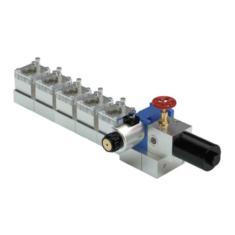
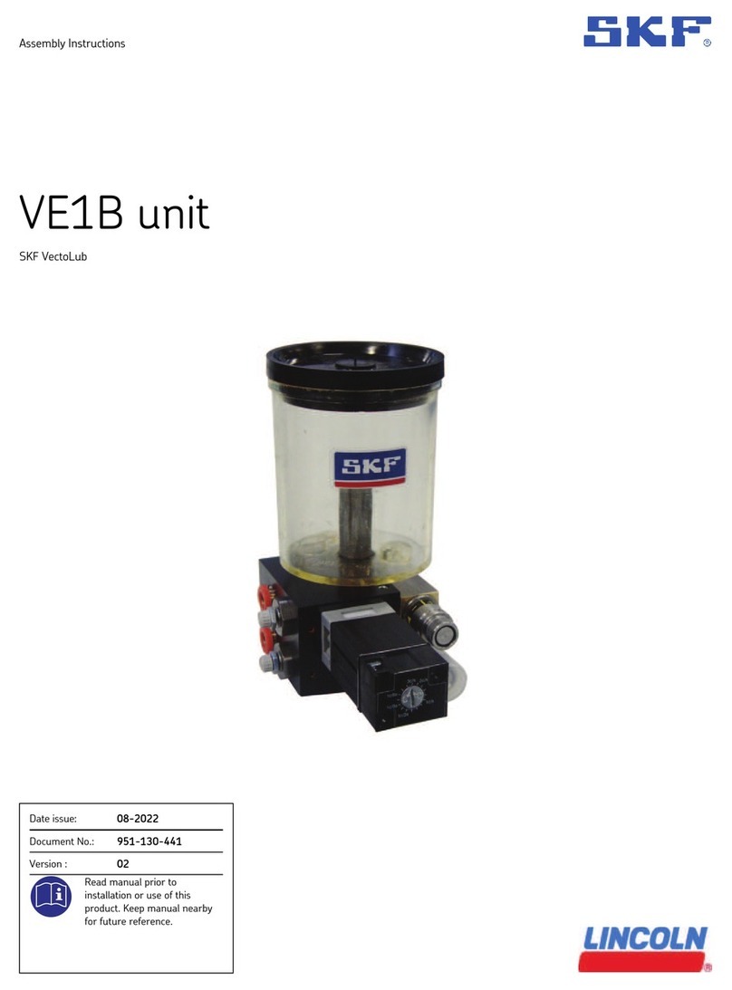
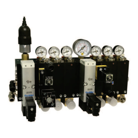
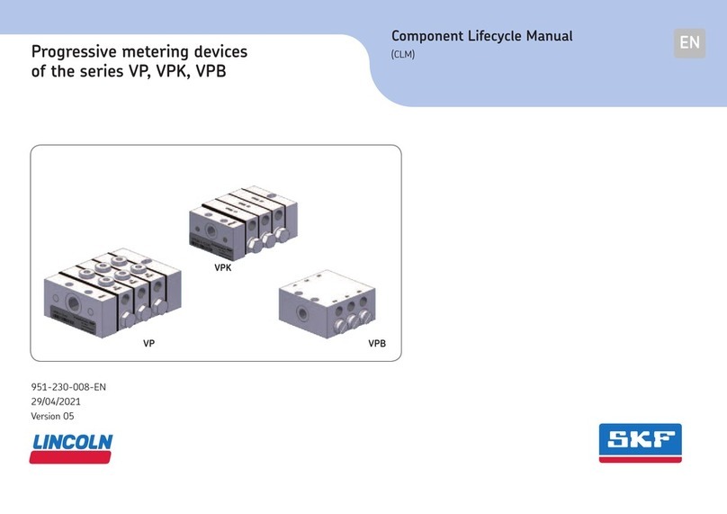
Lincoln Quicklub SSV L User manual

Subject to modifications
User Manual
OperationInstructions
2.2EN-20004-C11
LINCOLNGmbH•Postfach1263 •D-69183 Walldorf •Tel+49 (6227)33-0 •Fax +49(6227) 33-259
Quicklub - Progressive Metering Devices
for Grease and Oil
Model SSV L
B-SSVL-000a10

Page 2 of 20
Subject to modifications
User Manual
OperationInstructions
2.2EN-20004-C11
LINCOLNGmbH •Postfach 1263• D-69183Walldorf •Tel+49 (6227)33-0 •Fax +49(6227) 33-259
This User Manual was compiled on behalf of
- the manufacturer - by
Lincoln GmbH EdiDoc GmbH
Heinrich-Hertz-Str. 2-8 Erzberger Str. 8
D-69190 Walldorf D-68753 Waghäusel
All rights reserved.
Any duplication of this User Manual, in its entirety or in part,
by whatever means is prohibited without the prior consent in
writing of Lincoln GmbH.
Subject to modifications without prior notification.
© 2011 by
Phone: +49 (6227) 33-0
Fax: +49 (6227) 33-259
E-Mail: Lincoln@lincolnindustrial.de

Page 3 of 20
Subject to modifications
User Manual
OperationInstructions
2.2EN-20004-C11
LINCOLNGmbH •Postfach 1263• D-69183Walldorf •Tel+49 (6227)33-0 •Fax +49(6227) 33-259
Table of Contents
Page
Introduction
Explanation of Symbols Used ............................................ 4
User’s Responsibility ......................................................... 4
Environmental Protection .................................................. 4
Service .............................................................................. 4
Safety Instructions
Appropriate Use ................................................................ 5
Suitable Lubricants ...................................................... 5
General Safety Instructions ............................................... 5
Accident Prevention Regulations ....................................... 5
Operation, Maintenance, Repair ........................................ 5
Installation ......................................................................... 5
Installation
Connection Fittings, Screw-Type ....................................... 6
Inlet tube fittings ........................................................... 6
Outlet tube fittings ........................................................ 6
Hose fittings ................................................................. 6
High-pressure Hoses ................................................... 6
Control piston – Closure plugs ..................................... 6
Description
Progressive Metering Device Model SSVL ........................ 7
General ........................................................................ 7
Features of a Progressive Metering Device ................. 7
Rating .......................................................................... 7
Page
Operation
Applications ........................................................................ 8
Lubricant Distribution within the Metering Device ............ 10
Phase 1 + 2 ................................................................ 10
Phase 3 - 5 ................................................................. 11
Monitoring of the Operation ............................................. 12
System-dependent monitoring .................................... 12
Visual monitoring ........................................................ 12
Electrical monitoring ................................................... 13
Pressure relief valve ................................................... 13
Determining the Lubricant Output
byCombining Outlets ....................................................... 14
Outputs ....................................................................... 14
Outlet fittings .............................................................. 14
Troubleshooting ............................................................. 15
Technical Data
Rating .............................................................................. 17
Dimensions ...................................................................... 17
Tightening torques ........................................................... 17
Lines ................................................................................ 17
Spare Parts and Kits ...................................................... 18
EC Declaration of incorporation ................................... 19
Lincoln worldwide .......................................................... 20
Further Information can be found in the following manuals:
Technical Description Quicklub - Pump 203
Technical Description for “Electronic Control Units” of pump 203:
Printed-Circuit Board 236-13857-1 - Model H 1)
Printed-Circuit Board 236-13862-1 - Model V10 - V13 1)
Printed-Circuit Board 236-13870-3 - Model M 08 - M 23 1)
Installation Instructions
Parts Catalogue
List of Lubricants
Planning and Layout of Quicklub Progressive Systems
1) The model designation of the printed-circuit board is part of the pump model designation indicated on the pump nameplate,
e. g. : P 203 - 2XN - 1K6 - 24 - 1A1.10 - V10

Page 4 of 20
Subject to modifications
User Manual
OperationInstructions
2.2EN-20004-C11
LINCOLNGmbH •Postfach 1263• D-69183Walldorf •Tel+49 (6227)33-0 •Fax +49(6227) 33-259
Introduction
Explanation of Symbols Used
The following description standards are used in this manual:
Safety Instructions
Structure of safety instructions:
Pictogram
Signal word
Danger text
- Danger note
- How to avoid danger
The following pictograms are used in this manual and are
combined with the corresponding signal words:
1013 A94
4273a00
6001a 02
- ATTENTION
- CAUTION
- WARNING
- ATTENTION
- CAUTION
- WARNING
- NOTE
- IMPORTANT
The signal words give the seriousness of danger if the follow-
ing text is not observed:
ATTENTION refers to faults or damages on
machines.
CAUTION refers to bad damages and possi-
ble injuries.
WARNING refers to possible dangerous inju-
ries.
NOTE indicates improved operation of the
device.
IMPORTANT indicates special operating fea-
tures of the device.
Example:
10 13A94
ATTENTION!
When making use of other than the tested
spare parts, serious damage may affect
your device.
Therefore, for the operation of your device
always use original parts made by Lincoln
GmbH.
Furthermore, you will find the following text symbols in this
manual:
Listing of applicable statements
- Subpoint of applicable statements
1. Determination of the number or sequence of contents
ÂProcedural instruction
User's Responsibility
To ensure the safe operation of the unit, the user is responsi-
ble for the following:
1. The pump / system shall be operated only for the in-
tended use (see next chapter "Safety Instructions") and
its design shall neither be modified nor transformed.
2. The pump / system shall be operated only if it is in a
proper functioning condition and if it is operated in accor-
dance with the maintenance requirements.
3. The operating personnel must be familiar with this User
Manual and the safety instructions mentioned within and
observe these carefully.
The correct installation and connection of tubes and hoses, if
not specified by Lincoln GmbH, is the user's responsibility.
Lincoln GmbH will gladly assist you with any questions per-
taining to the installation.
Environmental Protection
Waste (e.g. used oil, detergents, lubricants) must be dis-
posed of in accordance with relevant environmental regula-
tions.
Service
The personnel responsible for the handling of the pump /
system must be suitably qualified. If required, Lincoln GmbH
offers you full service in the form of advice, on-site installation
assistance, training, etc. We will be pleased to inform you
about our possibilities to support you purposefully.
In the event of inquiries pertaining to maintenance, repairs
and spare parts, we require model specific data to enable us
to clearly identify the components of your pump / system.
Therefore, always indicate the part, model and series number
of your pump / system.

Page 5 of 20
Subject to modifications
User Manual
OperationInstructions
2.2EN-20004-C11
LINCOLNGmbH •Postfach 1263• D-69183Walldorf •Tel+49 (6227)33-0 •Fax +49(6227) 33-259
Safety Instructions
Appropriate Use
Use the SSV L lubricant metering devices only for dispensing
lubricants in centralized lubrication systems.
Suitable Lubricants
The progressive metering devices model SSV can be used
for dispensing
- mineral oils of at least 40 mm2/s (cST) or
- greases up to the penetration class NLGI 2
- see User Manual 2.0-40001
6001 a02
IMPORTANT
It must nevertheless be ensured that the
oilsor greasesuseddonotalter their con-
sistency significantly in thecourse of time o
r
underthe influence of temperature or
pressure.
General SafetyInstructions
The progressive centralized lubrication system connected
to the Quicklub pump model 203 must always be secured
with a pressure relief valve.
Lincoln SSV L lubricant metering devices are state of the
art.
Incorrect use may result in bearing damage caused by
poor or over-lubrication.
Each outlet that will be used must be equipped with a
screw fitting GE8LR1/4“, GE10LR1/4“ or
GE12LR1/4“ (GERV).
Due to the functional order of its pistons, progressive
metering devices SSVL6 to 14 will seize if the outlets po-
sitioned directly at the metering device housing are closed.
Modifications or changes to an installed system are not
admissible. Any modification must be subject to prior
consultation with the manufacturer of the lubrication sys-
tem.
Use only original Lincoln spare parts (see Parts Catalogue)
or the parts approved by Lincoln.
Regulations for Prevention of Accidents
To prevent accidents, observe all city, state and federal
safety regulation of the country in which the product will be
used.
Avoid the operation with
- unapproved parts.
- insufficient or contaminated lubricants.
1013A94
CAUTION!
Danger of injury in the case of serious
corrosion of metering device surfaces:
An increasing corrosion of the surfaces will
cause the balls pressed in to lose their hold.
Under pressure, they may suddenly burst
out and cause injuries.
For applications in corrosive environments,
use metering devices in stainless steel
version only.
Operation, Repair and Maintenance
Repairs should only be performed by authorized personnel
who are familiar with the repair instructions.
Installation
Install the metering devices at a suitable location in ac-
cordance with the lubrication diagram.
It is recommended that the metering devices be installed in
such a way that the outlets are not close to the chassis or
the attaching plate. This will facilitate troubleshooting in the
case the system is blocked.
The main metering devices with indicator pin must be
installed in such a way thattheindicator pinis easily visible.
Use only the main and feed lines specified by Lincoln and
adhere to the specified system pressures.
Table of contents
Other Lincoln Industrial Equipment manuals

Lincoln
Lincoln SKF DigitalSuper UFD10 Series User manual

Lincoln
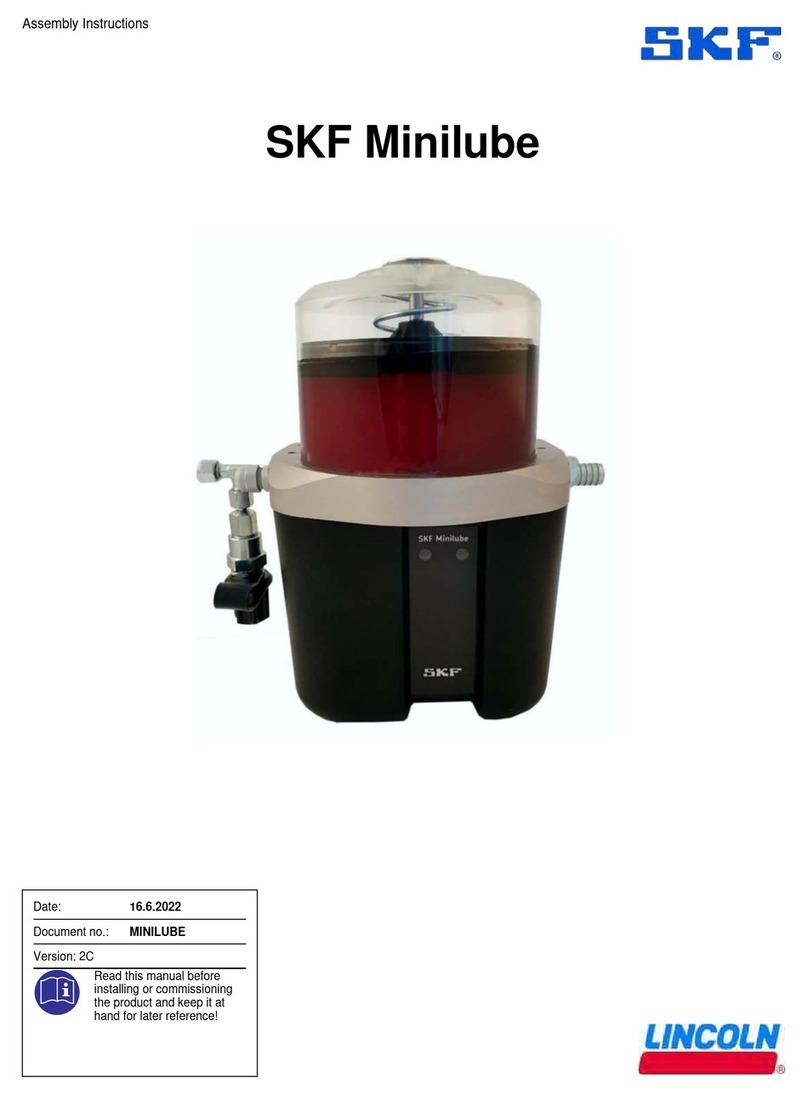
Lincoln SKF Minilube User manual

Lincoln
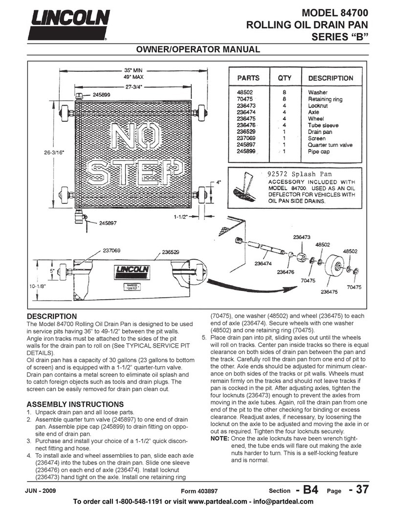
Lincoln 84700 Owner's manual

Lincoln
Lincoln M 16 User manual

Lincoln
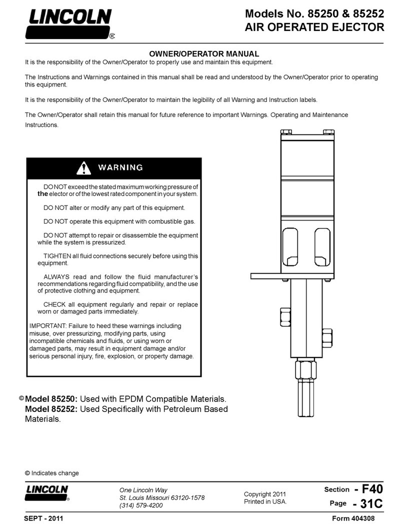
Lincoln 85250 Owner's manual

Lincoln
Lincoln Impinger Aperion 2424E User manual

Lincoln
Lincoln Impinger 1100 Series User manual

Lincoln
Lincoln A Series User manual

Lincoln
Lincoln SKF VectoLub VE1B unit User manual

Lincoln
Lincoln SKF VP Series User manual