manuals.online logo
Brands
  1. Home
  2. •
  3. Brands
  4. •
  5. Lincoln
  6. •
  7. Water Pump
  8. •
  9. Lincoln B Series User manual

Lincoln B Series User manual

Page
Section - Q5 - 2A
Form 402361
March 2002
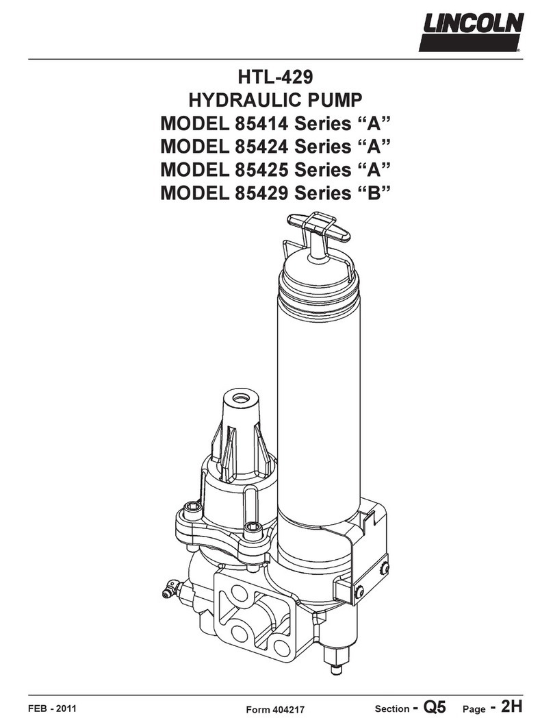
HYDRAULIC HAMMER PUMP
MODEL 85429
Series B
Page Number - 2
HYDRAULIC HAMMER PUMP
MODEL 85429
Series B
Form 402361
Table of Contents
Page
Safety .....................................................................................................2
General Description..................................................................................2
Appropriate Use.................................................................................2
Product Specifications.....................................................................2
Pump Operation.........................................................................................3
Excavators and ackhoes.........................................................................3
Skid Steers....................................................................................................3
Lubricant Recommendations.................................................................3
Pump Output Adjustment...........................................................................3
Pump Filling..................................................................................................3
Maintenance and Repair..........................................................................3
Installing Grease Cartridge.......................................................................4
Manual ( ulk) Filling....................................................................................4
Air Purging....................................................................................................4
Installing the Pump......................................................................................4
Filling Pump with Lubricant, Removing Empty Cartridge....................5
Return Spring Adjustment Procedure.....................................................5
Disassembly Procedure...........................................................................5
Pump Dimensions.....................................................................................6
Pump Cut-Aways....................................................................................7&8
Pump Exploded View..................................................................................9
Repair Parts List........................................................................................10
Trouble Shooting......................................................................................11
Safety
Read and carefully observe these operating instructions
before unpacking and operating the pump. The pump must
be operated, maintained and repaired exclusively by
persons familiar with the operating instructions. Local
safety regulations regarding installation, operation and
maintenance must be followed.
Operate this pump only after safety instructions and this
service manual are fully understood.
Indicates a potentially hazardous situation which, if not
avoided, could result in death or serious injury.
Indicates a potentially hazardous situation which, if not
avoided, may result in minor or moderate injury.
Safety Instructions
This equipment generates very high grease pressure.
Extreme caution should be used when operating this
equipment as material leaks from loose or ruptured
components can inject fluid through the skin and into the
body causing serious bodily injury. Adequate protection
is recommended to prevent splashing of material onto the
skin or into the eyes.
Description
General Description
This unit is a hydraulically operated, single acting, spring
return, positive displacement pump designed to deliver
grease under pressure. The pump is primarily designed to
lubricate bushings of the tool bit in Hydraulic Hammers.
The pump can be used to lubricate bushings and bearings
on grippers and crushers. The pump is designed to be
directly installed on the hammer, gripper or crusher and
connected to the hydraulic power supply of the carrier.
Grease outlet of the pump should be connected by hose to
the point of lubrication.
The pump could be attached to an SSV divider block for
multiple point lubrication.
The pump uses grease from standard 14.5 oz. grease
cartridges, eliminating the need for bulk filling equipment.
The pump may be filled from a bulk lubricant container if
desired.
Appropriate Use
This pump is exclusively designed to dispense grease in
Hydraulic Hammer and gripper/crusher applications.
It should be operated only with hydraulic power.
The maximum ratings given should not be exceeded.
Any other use not in accordance with the instructions will
result in loss of claims for warranty and liability.
Product Specification
Pump Ratio, Max. 2.16:1
Output per Stroke, 0.006 in3 (0.1 cm3)*
Hydraulic Inlet
Pressure (max.) 3,000 PSIG (208 bar)
Grease Reservoir Vol. 14.5 oz.
Max Inlet ack Pressure 725 PSIG (49.3 bar)
Output Pressure (max.) 6500 PSIG (450 bar)
Operating Temperature -10° F to +180° F
(-23°C to +80°C)
Hydraulic Port SAE #4 (7/16-20 UNF) O-Ring
Pump Outlet SAE #4 (7/16-20 UNF) O-Ring
Weight (empty) 16.3 lbs. (7.4 kg)
Weight (full) 17.3 lbs. (7.8 kg)
* NOTE: Pump output can be increased up to 0.031 in³
(0.5 cm³) by replacing the metering plug (23).
See Pump Output Adjustment.
If any fluid appears to penetrate the skin, get emergency
medical immediately. Do not treat as a simple cut.
Tell attending physician exactly what fluid was injected.
Page Number - 3
Form 402361
HYDRAULIC HAMMER PUMP
MODEL 85429
Series B
Pump Operation
The pump operates simultaneously with the hammer. Each
time the hammer is activated, the pump will deliver one shot
of the lubricant to the bushing of the hammer. The pump is
a single action pump and delivers the lubricant only on the
forward stroke of the piston 6, Illus. #2. The springs 8, 9,
and 10 will return the piston 6 to initial position, recharging
the pump. The springs of the pump can develop the force to
overcome 725 PSIG (49 bar) back pressure. This limiting
factor of the pump should be taken into consideration during
pump installation on the different types of the hammer
carriers.
The installation of the pump requires connection of the
pressure hydraulic line from the carrier to the pump inlet
and grease supply line from the pump outlet to the hammer
lubrication point.
The carriers have different hydraulic systems to operate the
machines and attachments. Depending on the type of the
carrier, hydraulic lines can vent the pressure very quickly or
have residual back pressure above 725 PSIG (49 bar)
retained in the lines for a long time.
Excavators and Backhoes
Main pressure of the hydraulic power supply of the excava-
tors and the backhoes drops below 725 PSIG (49 bar) very
rapidly when hammer is stopped. This will allow the spring
to return the piston to recharge the pump.
Connect the Pump to the Pressure Line. The pump will cycle
and deliver the lubricant as soon as the hammer starts to
operate. During the repositioning of the hammer to a new
location, the springs will return the piston to recharge the
pump for a new cycle. The lubrication of the hammer is done
during the hammer operation.
Carrier Type Connection Line
s
Excavator, Backhoe Pressure line
Skid Steers Return Line
Regardless of the pump connection to the pressure or
return line, if pressure fluctuation during the hammer
operation falls below 725 PSIG (49 bar) the pump can
deliver a small amount of lubricant due to the piston partial
movement. This additional lubricant output has to be taken
into consideration during selection of the Output Plug (23),
Illus. #4. to adjust the lubricant output.
Skid Steers
Skid steers with hydrostatic transmissions have a
back pressure in the return line, since hydraulic fluid
returned to the tank through the transmission itself. The
hydrostatic transmission is used to drive the skid steer
using hydraulic power generated by diesel motor. The back
pressure in the return line can vary from 350 to 1,200 PSIG
(24 to 82 bar) depending on the skid steer manufacturer,
but quickly drops to 50 PSIG (3.5 bar) or below during
hammer operation.
Connect the pump to the return line. The pump will deliver
the lubricant using the back pressure when hammer stops
to operate and will recharge during the hammer operation
when the pressure drops. So, the lubrication is done
during hammer repositioning to new location and pump will
recharge during hammer operation, this is opposite of the
lubrication cycle of the excavators and backhoes.
The connection of the pump to the carrier will depend only
on the type of the carrier and will not be dependent on the
type or manufacturer of the hammer:
ubricant Recommendations
Hammer manufacturers recommend lubricating while the
hammer is standing upright, resting on the tool to ensure
that the grease will penetrate downward between the tool
and the bushing. This recommendation is important when
lubrication is made using the manual grease gun and a
large amount of lubricant pumped into the hammer. The
upright position of the hammer with tool in a resting position
will ensure that the space between the piston and the tool
not be filled with the lubricant. Automatic lubrication with the
single stroke pump injects a very small amount of lubricant
during hammer operation and there is no need for the
hammer tool to be in a resting position.
How much lubrication is enough? The pump output should
be adjusted to make the length of the tool shank that is
traveling in and out of the bushing visibly wet with lubricant.
Do not over lubricant to the point that grease is clumping
and runs down on the tool.
Pump Output Adjustment
The pump is shipped with the minimum output metering
plug 23, Illus. #4. The plug output is 0.006 in³ (0.1 cm³).
The output of the pump can be increased by replacing the
metering plug with one of the optional plugs below:
Page Number - 4
HYDRAULIC HAMMER PUMP
MODEL 85429
Series B
Form 402361
INSTA ING THE PUMP
The pump should be installed directly on the hammer or the
carrier adapter for the hammer or attachment. It is prefera-
ble to mount the pump so that the cartridge housing (28) is
in the upright position (as shown on the front page), but
horizontal positioning is acceptable. Allow sufficient space
for cartridge changing and service. (See Fig. #2 for dimen-
sions). The red low-level indicator (18) should be readily
visible. mount the pump in a position that it will be protect-
ed from damage by any debris which may be encountered
when the hammer or attachment is in operation.
IMPORTANT: The feed line to the lube point must also be
protected from damage by armoring the line or other
suitable method of protection.
1. Lincoln recommends using Grade 8 fasteners, or
equivalent, for mounting the pump to the hammer or
adapter. It is important that two flat washer are used
between the bolt head or nut and the pump body of each
fastener. 1/2 grade 8 bolts, nuts and flat washer are
recommended. Apply 120 ft.-lbs. torque to the fasteners.
Fabricate a mounting bracket if necessary.
2. Using appropriate high-pressure hose, connect the
pump hydraulic inlet to the source of hydraulic power.
This may be either the supply or return lines to the
hammer. See above.
3. Fill the pump with lubricant. (See FILLING PUMP WITH
LU RICANT AND AIR PURGING INSTRUCTIONS.)
4. Attach the lubricant feed line to the lube outlet on the
pump.
5. Prime the lubricant feed line with lubricant.
6. Connect the lubricant feed line to the lube point. This
should be a direct connection, avoiding any grease fitting
couplers of possible.
7. Protect the lubricant feed line from damage by covering
with steel channel or angle iron if necessary.
IMPORTANT: The Low Level Indicator Rod (14) will extend
from the bottom of the pump when the grease cartridge
housing is empty. See (Fig. # 3, View D) Replace empty
cartridge or fill cartridge housing promptly with fresh lubri-
cant.
Adjusting the Spring Clip
For the Spring Clip (32) to properly retain the grease car-
tridge housing (28), it must be properly adjusted for either
bulk or cartridge filling. If the pump is to be used with
grease cartridges, the spring clip (32) must be adjusted to
fit tightly in the groove when a grease cartridge installed is
in the grease cartridge housing (28). If the pump is to be
bulk filled or filled with a pump, the spring clip should be
adjusted to fit into the groove tightly with no grease cartridge
installed in the cartridge housing (28). See Illus. #3, View A.
Refer to appropriate section for details on adjustment.
1. 271924 - 0.031 in³ (0.5 cm³)
2. 271925 - 0.018 in³ (0.3 cm³)
3. 271926 - 0.012 in³ (0.2 cm³)
4. 271927 - 0.006 in³ (0.1 cm³)
Always use Lincoln Industrial parts for service and repair.
Maintenance and Repair
Relieve pressure from the pump and supply lines before
servicing or repairing the pump, to reduce the risk of an
injury from injection, splashing fluid or moving parts.
Filling Pump with Grease
Removing Empty Cartridge
1. Disengage the retaining clip from
the follower handle as shown in
the illustration, below.
2. Pull the spring clip of the reservoir
retainer by grasping the finger tab
on the clip and disengage the clip
fingers from the housing groove.
Loosen the Grease Cartridge
Housing a couple of turns to break
the seal.
3. Pull back the follower handle until the follower rod is fully
extended and latch the follower rod groove into the slot in
the tube cap.
4. Unscrew the grease cartridge housing (28) from the pump
head (11).
5. Carefully release the follower handle to eject the empty
cartridge from the container tube.
Installing Grease Cartridge
1. Visually check follower seal lip direction before loading a
new cartridge. The follower seal lip must be directed
toward the follower handle for cartridge loading. See
illustration below. To change the direction of the follower
seal, unscrew the tube cap from the container tube and
pull on handle to remove the follower seal from the tube.
Flip the follower seal over and re-assemble.
2. Pull back on the follower handle and latch the follower
rod groove into the slot on the tube cap.
3. Remove the plastic cap from the grease cartridge and
insert the cartridge into the container tube.
4. Remove the pull-tab from the grease cartridge. Pull the
finger tab on the spring retainer (31) back to clear the
grease cartridge housing (28) as the housing is placed
into the opening in the pump head (11). Screw grease
cartridge-housing (28) into the pump head (11) and
tighten.
5. Release follower rod from slot. Purge air from pump.
See air-purging instructions.
6. Latch the retaining clip over the top of the follower handle
to prevent the follower rod from protruding from the
grease cartridge housing.
Page Number - 5
Form 402361
HYDRAULIC HAMMER PUMP
MODEL 85429
Series B
7. If installing a grease cartridge for the first time, see
Installing the Reservoir Retainer, above for proper
adjustment.
5. Operate filler pump to fill container tube while watching
follower rod. The container is full when notch on follower
rod becomes visible.
6. Disengage follower rod from follower and push follower
rod into container tube. Air purging is not required unless
the Grease Cartridge Housing (28) was removed from the
Pump Head (11).
Removing Empty Cartridge
1. Loosen the Grease Cartridge Housing (28) a couple of
turns from the pump head (11) to allow air to enter the
cartridge housing.
2. Pull back on the Follower Handle (30) until the follower
rod is fully extended, and latch the follower rod groove
into the slot on the tube cap.
3. Unscrew the Grease Cartridge Housing (28) from the
Pump Head (11).
4. Carefully release the follower handle to eject the empty
cartridge from the container tube.
Disassembly Procedure (See Exploded View
and Fig. #3)
Tools Required:
- 11/16 wrench
- 3/4 wrench
- 5/16 Allen wrench
1. Loosen the Grease Cartridge Housing (28) a turn or two
and pull the Follower Handle (30) until the notch on the
follower rod can be latched into the slot in the tube cap.
2. Remove the Grease Cartridge Housing (28).
3. Remove the Grease Cartridge is present.
4. Remove the packing (27) from the pump head (11).
5. Disconnect the hydraulic supply line from the cylinder
block (2).
6. Loosen each of the four cap screws (1) equally until all
tension is removed from the springs (8, 9 & 10) inside
the cylinder block (2).
7. Remove the screws (1) followed by the cylinder block (2).
8. Remove the piston (4) from the cylinder block (2).
9. Remove the packing (3) from the piston (4).
10. Lift the spring retainer (5) until it can be pulled from of
the plunger (6).
11. Remove all the springs (8, 9 & 10) and washer (7) from
the pump body (11).
12. Remove the packing (3) from the pump body (11).
13. Remove the metering plug (23) and O-Ring (20) from
the pump body (11).
14. Remove the outlet check adapter (19), O-Ring (20),
spring (21) and check ball (22) from the pump body (11).
15. Remove the vent valve (12) or filler fitting (29) from the
pump body (11).
16. Remove the low-level indicator as a unit, (see illus. #3,
veiw D) by removing the bushing from the pump body
(11).
17. Disassemble the low level indicator by removing the
indicator cap (18) and lower retaining ring (13) from the
indicator rod (14).
Manual (Bulk) Filling
1. Pull the spring clip of the reservoir retainer by grasping
the finger tab on the clip and disengage the clip fingers
from the housing groove while unscrewing the Grease
Cartridge Housing (28) from the Pump Head (11).
2. The follower seal lip must be directed towards the pump
head when cartridges are not used. To change direction
of the follower, unscrew tube cap from container tube and
pull on handle to remove follower from tube. Flip follow-
er seal over and re-assemble.
3. Pack the follower end of the container tube with grease to
eliminate air pockets.
4. Dip the packed end of the container tube about one inch
into bulk container.
5. Slowly pull follower handle back while gradually pushing
the container tube deeper into the grease,
6. When the follower rod is fully extended, latch the groove
in the follower rod with the slot in the reservoir cap.
7. Wipe excess grease from the outside of the container
tube.
8. Pull the finger tab on the spring retainer (31) back to
clear the grease cartridge housing (28) as the housing is
placed into the opening in the pump head (11). Screw
grease cartridge-housing (28) into the pump head (11)
and tighten.
9. Adjust the spring retainer as required, see Installing the
Reservoir Retainer.
10.Latch the retaining clip over the top of the follower handle
to prevent the follower rod from protruding from the
grease cartridge housing.
Air Purging
1. Engage the follower rod with the follower by lightly pulling
up and rotating the follower handle.
2. Push down on follower handle while pressing button on
Vent Valve (12) to force any air pockets out of Pump Head
(11).
3. Wipe excess grease from Vent Valve (12).
Bulk Filling with Filler Pump
1. Remove Vent Fitting (12) and replace with Grease Fitting
5003 (29), included in package.
2. The follower seal lip must be directed toward the pump
head when cartridges are not used.
3. Engage the follower rod with the follower by lightly pulling
up and rotating the follower handle.
4. Push filler pump socket onto filler nipple.
Follower
Handle Tube
Cap Container
Tube
Follower
Rod Follower Seal
Lip (Cartridge
Position)
Fig. # 1
Page Number - 6
HYDRAULIC HAMMER PUMP
MODEL 85429
Series B
Form 402361
18. Carefully slide the indicator rod (14) from the bushing
(17). The spring (16), washer (15) may now be
removed from the indicator rod (14).
19. Remove O-ring (25) from the bushing (17).
20. Remove the spring clip (32) and plate (33) from the
pump body (11) by removing two screws (35) and lock
washer (34).
21. Disassemble the grease cartridge housing (28) by
unscrewing the cap counterclockwise from the tube.
Slide the rod, spring and packing assembly out of the
reservoir tube.
22. Remove the retaining clip (31) from the cap.
23. Compress the spring and remove the follower handle
(30) from the rod.
24. Carefully release the spring tention and remove the
spring and cap from the follower rod.
25. The follower assembly (26) can be removed from the
follower rod by sliding up the rod towards the handle
end of the rod.
26. All components should be cleaned. Worn or damaged
parts should be replaced. All packings and seals
should be replaced.
27. Reassemble in the reverse order of assembly. Use
views in illus. #3 for aid in installing packings correctly
and in reassembly of the pump. Lincoln recommends
using thread locking coumpound (such as Loctite #242
or equivalent) for all threaded connections during
reassembly.
28. When installing the spring clip (32), adjust as required
for cartridge or bulk filling. See Installing Grease
Cartridge or Manual Bulk) Filling as required for
adjustment procedures.
29. When installing the cylinder head (2) the cap screws (1)
should betightened to a torque of 13-14 ft.-lbs.
30. If pump is to be reassembled without filling the grease
reservoir, install the grease cartridge housing (28) with
the follower rod groove latched into the slot in the tube
cap. This will prevent the low level indicator rod (14)
from binding with the follower assembly (26).
Page Number - 7
Form 402361
HYDRAULIC HAMMER PUMP
MODEL 85429
Series B
Fig. #2
Page Number - 8
HYDRAULIC HAMMER PUMP
MODEL 85429
Series B
Form 402361
Fig. #3
View A
View B
View C
View D
Page Number - 9
Form 402361
HYDRAULIC HAMMER PUMP
MODEL 85429
Series B
Fig. #4
1
2
3
4
5
6
10
9
8
7
3
27
11
29
12
15
14
25
17
18
13
23
20
22
19
21
28
30
26
31
36
20
15
16
32
33
34
35
Page Number - 10
HYDRAULIC HAMMER PUMP
MODEL 85429
Series B
Form 402361
Notes:
1. Included in 271936 Seal Kit
Item No. Qty. Description Repair Part No
.
1 4 SocketHead Screw (3/8-16 x1-1/4") 271923
2 1 Cylinder Block 271935
3 2 U-Cup (polyurethane) (See Note #1)
4 1 Piston 271921
5 1 Spring Retainer 271931
6 1 Plunger 271922
7 1 Washer 48397
8 1 Spring 249966
9 1 Spring 249965
10 1 Spring 249964
11 1 Pump Head 271933
12 1 VentValve 243307
13 1 Retaining Ring 68405
14 1 Indicator Rod 249976
15 2 Washer 48358
16 1 Spring 249967
17 1 Bushing 271929
18 1 Indicator Cap 249969
19 1 OutletHousing 249957
20 1 O-Ring (Nitrile) (See Note #1)
21 1 Spring 55005
22 1 Check Ball 66030
23 1 Metering Plug (0.1 cc) 271927
24 1 O-Ring (nitrile) (See Note #1)
25 1 O-Ring (Nitrile) (See Note #1)
26 1 Follower Assembly 93485
27 1 Packing (neoprene) 249968
28 1 Grease Cartridge Housing (incl. #26 &30) 249952
29 1 Fill Fitting (Optional) 5003©
30 1 Follower Handle 261514
31 1 Retaining Clip 272216
32 1 Spring Clip 272257
33 1 Plate 272258
34 2 Lockwasher #10 66213
35 2 #10-32 x1/2" Button Head Cap Screw 272259
1 Seal Kit 271936
REPAIR PARTS LIST
© Indicates change
Page Number - 11
Form 402361
HYDRAULIC HAMMER PUMP
MODEL 85429
Series B
Condition Possible Cause Corrective Action
Pump does notoperate. No hydraulic pressure to pump. Turn on or connecthydraulic supply.
Piston or plunger is stuck. Disassemble pump,inspectfor
damaged or worn parts. Replace
ifnecessary.
Hydraulic Pressure is too high Check hydraulic pressures & select
or low for Return Springs springs from pressure chart.
installed.
Broken Return Spring(s) Replace all Return Springs.
Pump does not Grease cartridge is empty. Replace emptygrease cartridge.
dispens grease. Follower is stuck. Check Cartridge Housing for damage
.
Worn Plunger or Pump Body. Replace worn parts.
Lubricant or hydraulic Worn seal on plunger or Disassemble pump, replace worn
fluid in spring chamber. piston. seals.
TROUBLESHOOTING
Page Number - 12
HYDRAULIC HAMMER PUMP
MODEL 85429
Series B
Form 402361
Americas:
One Lincoln Way
St. Louis, MO 63120-1578
USA
Phone +1.314.679.4200
Fax +1.800.424.5359
Europe/Africa:
Heinrich-Hertz-Str 2-8
D-69183 Walldorf
Germany
Phone +49.6227.33.0
Fax +49.6227.33.259
Asia/Pacific:
25 Intl usiness Park
#01-65 German Centre
Singapore 609916
Phone +65.562.7960
Fax +65.562.9967
© Copyright 2001
Printed in USA
Web site:
www.lincolnindustrial.com

Other manuals for B Series

11

This manual suits for next models

1

Other Lincoln Water Pump manuals

Lincoln SKF FlowMaster II A Series Instruction Manual

Lincoln

Lincoln SKF FlowMaster II A Series Instruction Manual

Lincoln ZPU 08 User manual

Lincoln

Lincoln ZPU 08 User manual

Lincoln FlowMaster C Series User manual

Lincoln

Lincoln FlowMaster C Series User manual

Lincoln SKF J Series User manual

Lincoln

Lincoln SKF J Series User manual

Lincoln SKF CLP Touch User manual

Lincoln

Lincoln SKF CLP Touch User manual

Lincoln 1296 User manual

Lincoln

Lincoln 1296 User manual

Lincoln SKF FlowMaster II A Series Instruction Manual

Lincoln

Lincoln SKF FlowMaster II A Series Instruction Manual

Lincoln A Series User manual

Lincoln

Lincoln A Series User manual

Lincoln PILE DRIVER III User manual

Lincoln

Lincoln PILE DRIVER III User manual

Lincoln D Series User manual

Lincoln

Lincoln D Series User manual

Lincoln A Series User manual

Lincoln

Lincoln A Series User manual

Lincoln SKF A Series Instruction Manual

Lincoln

Lincoln SKF A Series Instruction Manual

Lincoln SKF ContiMaster User manual

Lincoln

Lincoln SKF ContiMaster User manual

Lincoln B Series Parts list manual

Lincoln

Lincoln B Series Parts list manual

Lincoln HTL 101 User manual

Lincoln

Lincoln HTL 101 User manual

Lincoln J Series Owner's manual

Lincoln

Lincoln J Series Owner's manual

Lincoln CENTRO-MATIC 84944 User manual

Lincoln

Lincoln CENTRO-MATIC 84944 User manual

Lincoln 1550 Product manual

Lincoln

Lincoln 1550 Product manual

Lincoln Quicklub 223 User manual

Lincoln

Lincoln Quicklub 223 User manual

Lincoln PMA - 2 User manual

Lincoln

Lincoln PMA - 2 User manual

Lincoln SKF TLGB 20 User manual

Lincoln

Lincoln SKF TLGB 20 User manual

Lincoln C Series User manual

Lincoln

Lincoln C Series User manual

Lincoln 85622 Parts list manual

Lincoln

Lincoln 85622 Parts list manual

Lincoln P 203 User manual

Lincoln

Lincoln P 203 User manual

Popular Water Pump manuals by other brands

moyno 20352 Service manual

moyno

moyno 20352 Service manual

SKF SKF 729124 Instructions for use

SKF

SKF SKF 729124 Instructions for use

XTline XT121200 user manual

XTline

XTline XT121200 user manual

BGS technic 3064 instruction manual

BGS technic

BGS technic 3064 instruction manual

AeroBed 103H-AU instruction manual

AeroBed

AeroBed 103H-AU instruction manual

Becker U 5.201 operating instructions

Becker

Becker U 5.201 operating instructions

STA-RITE DURA-JET JSACL owner's manual

STA-RITE

STA-RITE DURA-JET JSACL owner's manual

Aqua DET 4 quick start guide

Aqua

Aqua DET 4 quick start guide

Verderflex Dura MK IV 05 operating manual

Verderflex

Verderflex Dura MK IV 05 operating manual

Flux F 550 Series operating instructions

Flux

Flux F 550 Series operating instructions

Berkeley Pumper owner's manual

Berkeley

Berkeley Pumper owner's manual

ITT GOULDS PUMPS JCU Installation, operation and maintenance manual

ITT

ITT GOULDS PUMPS JCU Installation, operation and maintenance manual

Enerwatt EWP-SUB-103GPH user manual

Enerwatt

Enerwatt EWP-SUB-103GPH user manual

Stairs ST SERIES Installation and operating instructions

Stairs

Stairs ST SERIES Installation and operating instructions

Flowserve FM Centrifugal Pump PCN=71576526 User instructions

Flowserve

Flowserve FM Centrifugal Pump PCN=71576526 User instructions

Aqua TEXMO AHS 02/03 INSTALLATION/SPACE PARTS MANUAL

Aqua

Aqua TEXMO AHS 02/03 INSTALLATION/SPACE PARTS MANUAL

Resol FlowSol B HE WMZ Manual for the specialised craftsman

Resol

Resol FlowSol B HE WMZ Manual for the specialised craftsman

GREAT PLAINS PA-120DEF owner's manual

GREAT PLAINS

GREAT PLAINS PA-120DEF owner's manual

manuals.online logo
manuals.online logoBrands
  • About & Mission
  • Contact us
  • Privacy Policy
  • Terms and Conditions

Copyright 2025 Manuals.Online. All Rights Reserved.