Link 60K AIR LINK User manual

Link Suspensions of Canada
601 18th Ave
Nisku, AB T9E 7T7 Canada
www.linkmfg.com
QUESTIONS?
CALL CUSTOMER
SERVICE
1-888-472-9326
60K AIR LINK Susp.
11/27/2019
INSTALLATION
INSTRUCTIONS
60K AIR LINK®
TANDEM DRIVE SUSPENSION

AIR LINK 60k Suspension –Installation Manual Rev.00 (11/20/2019)
Proprietary and Confidential 2
Link Suspensions of Canada
601 –18th Avenue
Nisku, Alberta
Ph: 888-472-9326
Fax: 780-955-2386
Email: [email protected]
Link Manufacturing Ltd.
223 –15th Street NE
Sioux Center, Iowa
51250
Ph: 800-222-6283
Fax: 712-722-4876
Email: [email protected]

AIR LINK 60k Suspension –Installation Manual Rev.00 (11/20/2019)
Proprietary and Confidential 3
Table of Contents:
SECTION 1: COMPONENT TERMINOLOGY ................................................................................... 5
SECTION 2: INTRODUCTION......................................................................................................... 6
Description.................................................................................................................................. 6
Safety Notice............................................................................................................................... 6
SECTION 3: ASSEMBLY ................................................................................................................. 7
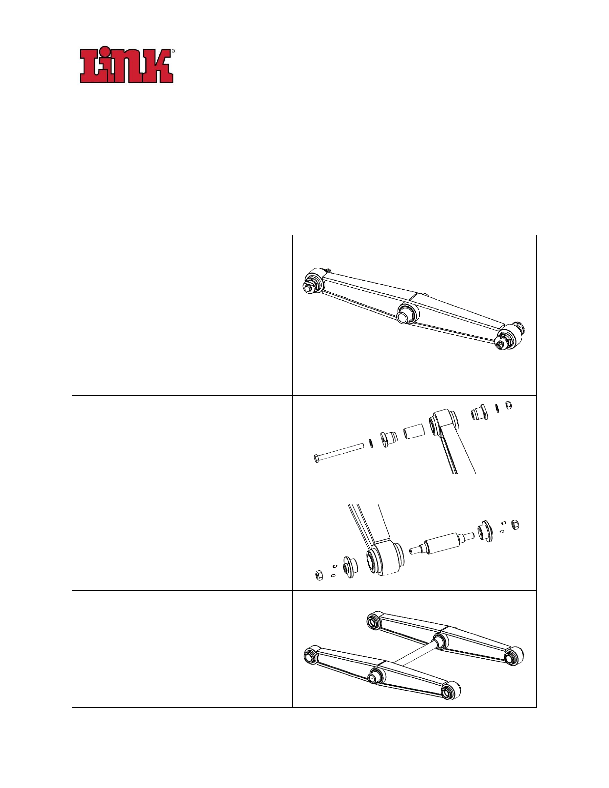
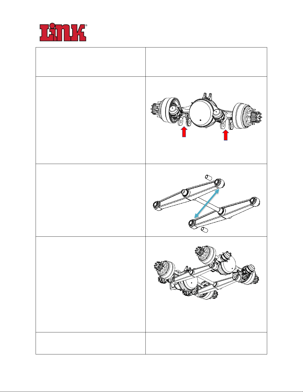
Assemble the Axle to the Walking Beams (2-1/2ӯ Adapter Bushing)...................................... 7
Required Components ............................................................................................................ 7
Required Tools ........................................................................................................................ 8
Procedure................................................................................................................................ 8
Assemble the Axle to the Walking Beams (3ӯ Adapter Bushing)........................................... 12
Required Components .......................................................................................................... 12
Required Tools ...................................................................................................................... 12
Procedure.............................................................................................................................. 13
Install Frame Mounted Components........................................................................................ 17
Required Components .......................................................................................................... 17
Required Tools ...................................................................................................................... 17
Procedure.............................................................................................................................. 18
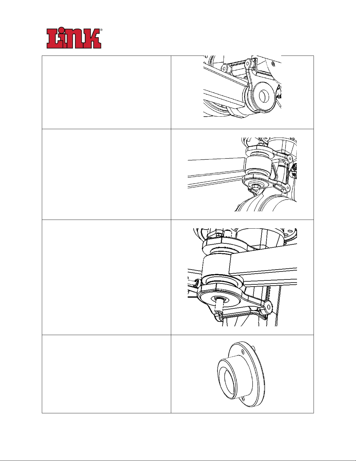
Install the Trailing Arm.............................................................................................................. 20
Required Components .......................................................................................................... 20
Required Tools ...................................................................................................................... 20
Procedure.............................................................................................................................. 20
Install Air Spring........................................................................................................................ 23
Required Components .......................................................................................................... 23
Required Tools ...................................................................................................................... 23
Procedure.............................................................................................................................. 24
Install the Shock........................................................................................................................ 27
Required Components .......................................................................................................... 27
Required Tools ...................................................................................................................... 27
Procedure.............................................................................................................................. 28
Install Restraint Strap................................................................................................................ 30

AIR LINK 60k Suspension –Installation Manual Rev.00 (11/20/2019)
Proprietary and Confidential 4
Introduction .......................................................................................................................... 30
Required Components.......................................................................................................... 30
Required Tools ...................................................................................................................... 30
Procedure.............................................................................................................................. 31
Install the Height Control Valve Linkage Rod ........................................................................... 32
Introduction .......................................................................................................................... 32
Required Components (Height Control Valve) ..................................................................... 32
Required Tools ...................................................................................................................... 32
Procedure (Height Control Valve Installation)...................................................................... 33
Required Components (Pin Connection) .............................................................................. 33
Procedure (Pin Connection).................................................................................................. 34
Required Components (Bolt Connection)............................................................................. 36
Procedure (Bolt Connection) ................................................................................................ 36
Install the Walking Beam/Axle Assembly to the Trailing Arms ................................................ 39
Required Tools ...................................................................................................................... 39
Install Control Rod Components............................................................................................... 41
Plumbing the Air System........................................................................................................... 43
SECTION 4: SUSPENSION FINAL SETUP...................................................................................... 44
APPENDIX A: TORQUE SUMMARY TABLE ..................................................................................... 45
APPENDIX B:.................................................................................................................................. 46
APPENDIX C:.................................................................................................................................. 47

AIR LINK 60k Suspension –Installation Manual Rev.00 (11/20/2019)
Proprietary and Confidential 5
SECTION 1: COMPONENT TERMINOLOGY

AIR LINK 60k Suspension –Installation Manual Rev.00 (11/20/2019)
Proprietary and Confidential 6
SECTION 2: INTRODUCTION
Description
This document is intended to provide general guidelines for the installation of the Air Link TM
system in a new chassis at the OEM level.
In this case, the design has been worked into the chassis based on requirements outlined by the
OEM (capacity, ride height, spread, etc.).
This manual is to cover the general assembly of a 60,000 lbs capacity Air Link TM suspension
with adapter end bushings. Each kit is specific to the requirements of each customer and
therefore not all sections may specifically apply to each customer specific application. In such
cases, refer to the OEM information for proper installation details.
Some part numbers have been supplied for generic parts however, the suspension layout
drawing should be used in conjunction with this manual to provide specific details of the
suspension component part numbers and configuration.
The proper assembly and setup of the Air Link TM suspension has been proven to provide
customers with years of trouble free, service, which is our goal for all our users.
Safety Notice
These processes are provided with the understanding that the work will be performed by
qualified personnel, using appropriate industry safety standards. In all cases, safety and
common sense must be at the forefront when working with heavy equipment. Carefully read
and understand the work instructions prior to commencing work, and all appropriate safety
precautions are the responsibility of the technicians performing this work.
In this document, notes, cautions and warnings are placed at critical steps that should be read
carefully.
•Notes will provide any tips and tricks to make the work as efficient as possible.
•Cautions are to warn of key features that need to be safeguarded or measurements that
need to be maintained.
•Warnings are outlined where the danger of personal injury is most likely.

AIR LINK 60k Suspension –Installation Manual Rev.00 (11/20/2019)
Proprietary and Confidential 7
SECTION 3: ASSEMBLY
Assemble the Axle to the Walking Beams (2-1/2ӯ Adapter Bushing)
Required Components
Description
Quantity
Image
Assembled rear axle
(Customer Supplied)
2
Sleeve Bushing (2-1/2” ID)
(Link P/N: 206-00-006)
4
Bolt, Hex, Gr.8, 1”Ø-14UNF x 11”
(Link P/N: 201-00-612)
2
Washer, Flat, SAE, 1ӯ
(Link P/N: 201-01-075)
4
Nut, Hex, Cone Lock, 1ӯ
(Link P/N: 201-02-315)
2
Inner Sleeve
(Link P/N: 206-00-012)
2
End Cap
(Link P/N: 206-00-013)
4
Adapter Shaft, Alignment
(Link P/N: 322-80-135)
2
Adapter End Cap, Alignment
(Link P/N: 322-80-140)
4
Nut, Hex, Stover, 1ӯ-14NUF
(Link P/N: 201-02-275)
4
Set Screw, UNC 3/8"Ø X 3/4"
(Link P/N: 201-00-606)
8
Walking beam [1][2]
(Link Supplied)
2
[1] The walking beam is not available without bushings.
[2] Walking beam supplied assembled with bushings in kit. Breakdown above provided for replacement detail.

AIR LINK 60k Suspension –Installation Manual Rev.00 (11/20/2019)
Proprietary and Confidential 8
Required Tools
▪Hammer (Mallet)
▪Wrench (1 1/2”)
▪Socket (1 1/2”)
▪Torque wrench 500 ft-lb minimum
▪Digital Level
▪Pliers
▪Alignment punch
Procedure
1. Each walking beam has a center
bushing, a straight adapter
bushing in one end and an
eccentric adapter bushing in the
other end.
Note: Typical set-up expected.
Eccentric adapter bushing will be
at diagonally opposite corners of
the suspension.
2. Disassemble the straight adapter
bushing bolt, washers, nut, end
caps and inner sleeve from one
end and keep them at hand for
assembly.
3. Disassemble the eccentric
adapter bushing nuts, end caps
w/ set screws and shaft from the
other end and keep them at hand
for assembly.
4. Insert the trunnion tube into the
center bushing of each walking
beam.
Note: Trunnion tube must be
installed before the walking
beams are installed to the axles.

AIR LINK 60k Suspension –Installation Manual Rev.00 (11/20/2019)
Proprietary and Confidential 9
Note: Trunnion tube is intended
to be loose in the center bushing.
(Freely rotate and some end to
end play).
5. Position both drive axles to allow
access to the axle hangers to
install the walking beams.
Note: The orientation of the axles
is dependent on each OEM
assembly process.
Caution: Some walking beams are
orientation dependant. Be sure to
position beams correctly.
6. Position the inner sleeve from
each adapter bushing into the
outer bushing sleeve in the
walking beam.
Note: The position of each
straight adapter bushing must be
at the diagonal ends of each
walking beam.
7. Align the axle hangers with the
walking beam assembly.
Note: One axle can be done at a
time if the process requires it.
Warning: Axles and suspension
components are heavy. Avoid
pinch points during assembly.
8. Align each bushing inner sleeve to
the axle hanger bore holes.

AIR LINK 60k Suspension –Installation Manual Rev.00 (11/20/2019)
Proprietary and Confidential 10
9. Install the end caps, adapter
bushing bolts, washers and nuts.
10. Next slide the eccentric adapter
shaft through the bushing and
the axle connector bore.
Caution: Removing the tires,
drum and disconnecting the
shoes may be needed to install
the bushing shaft and get access
to the bushing nut on the outside.
Follow axle manufacturer’s
recommended procedures for
completing this step.
11. Back off set screws off enough so
that the point does not protrude
past the inside of the cap.

AIR LINK 60k Suspension –Installation Manual Rev.00 (11/20/2019)
Proprietary and Confidential 11
12. Install the eccentric adapter
bushing nuts, end caps w/ set
screws onto each side of each
shaft.
13. Set the pinion angle of each axle
then torque the bushing nuts of
each bushing.
Note: Keep the orientation of the
end caps straight up and down as
shown. This is the neutral
position for the eccentric
bushing.
Caution: Ensure offset of the end
cap is oriented in the up position
as shown.
Torque specification: 490 ft-lb. [665 Nm]
14. Check completed assembly to
make sure all components have
been installed. Check that each
axle has an adapter bushing and
an eccentric adapter bushing
connected to it.
Note: Tighten the hardware to
secure the connection with no
play. Final torque done at
alignment stage. See Appendix B.

AIR LINK 60k Suspension –Installation Manual Rev.00 (11/20/2019)
Proprietary and Confidential 12
Assemble the Axle to the Walking Beams (3ӯ Adapter Bushing)
Required Components
Description
Quantity
Image
Assembled rear axle
(Customer Supplied)
2
Sleeve Bushing (3” ID)
(Link P/N: 206-00-007)
4
Bushing Adapter Kit Nut Type
(Link P/N: 206-00-008)
2
Cotter Pin 3/16ӯ
(Link P/N: 201-01-075)
4
Adapter Shaft, Alignment 3ӯ
(Link P/N: 346-50-010)
2
Adapter End Cap, Alignment 3ӯ
(Link P/N: 346-50-011)
4
Nut, Hex, Stover, 1ӯ-14NUF
(Link P/N: 201-02-275)
4
Set Screw, UNC 3/8"Ø X 3/4"
(Link P/N: 201-00-606)
8
Walking beam [1][2]
(Link Supplied)
2
[1] The walking beam is not available without bushings.
[2] Walking beam supplied assembled with bushings in kit. Breakdown above provided for replacement detail.
Required Tools
▪Hammer (Mallet)
▪Wrench (1 1/2”)
▪Socket (1 1/2”)
▪Torque wrench 500 ft-lb minimum
▪Digital Level
▪Pliers
▪Alignment punch

AIR LINK 60k Suspension –Installation Manual Rev.00 (11/20/2019)
Proprietary and Confidential 13
Procedure
1. Each walking beam has a center
bushing, a straight adapter
bushing in one end and an
eccentric adapter bushing in the
other end.
Note: Typical set-up expected.
Eccentric adapter bushing will be
at diagonally opposite corners of
the suspension.
2. Disassemble the straight adapter
sleeve, slotted nuts and cotter
pins from both ends and keep
them at hand for assembly.
3. Disassemble the eccentric
adapter bushing nuts, end caps
w/ set screws and shaft from the
other end and keep them at hand
for assembly.
4. Insert the trunnion tube into the
center bushing of each walking
beam.
Note: Trunnion tube must be
installed before the walking
beams are installed to the axles.
Note: Trunnion tube is intended
to be loose in the center bushing.
(Freely rotate and some end to
end play).

AIR LINK 60k Suspension –Installation Manual Rev.00 (11/20/2019)
Proprietary and Confidential 14
5. Position both drive axles to allow
access to the axle hangers to
install the walking beams.
Note: The orientation of the axles
is dependent on each OEM
assembly process.
Caution: Some walking beams are
orientation dependant. Be sure to
position beams correctly.
6. Align the axle hangers with the
walking beam assembly.
Note: One axle can be done at a
time if the process requires it.
Warning: Axles and suspension
components are heavy. Avoid
pinch points during assembly.
7. Slide each straight adapter sleeve
through the axle hanger bore
holes.
8. Install the slotted nuts and cotter
pins.
Torque specification: 1200-1250 ft-lb.
[1627-1695 Nm]

AIR LINK 60k Suspension –Installation Manual Rev.00 (11/20/2019)
Proprietary and Confidential 15
9. Next slide the adapter alignment
shaft through the bushing and
the axle hanger bore.
Caution: Removing the tires,
drum and disconnecting the
shoes may be needed to install
the bushing shaft and get access
to the bushing nut on the outside.
Follow axle manufacturer’s
recommended procedures for
completing this step.
10. Back off set screws off enough so
that the point does not protrude
past the inside of the cap.
11. Install the eccentric adapter
bushing nuts, end caps w/ set
screws onto each side of each
shaft.
12. Set the pinion angle of each axle
then torque the bushing nuts of
each bushing.
Note: Keep the orientation of the
end caps straight up and down as
shown. This is the neutral
position for the eccentric
bushing.

AIR LINK 60k Suspension –Installation Manual Rev.00 (11/20/2019)
Proprietary and Confidential 16
Caution: Ensure offset of the end
cap is oriented in the up position
as shown.
Torque specification: 490 ft-lb. [665 Nm]
13. Check completed assembly to
make sure all components have
been installed. Check that each
axle has an adapter bushing and
an eccentric adapter bushing
connected to it.
Note: Tighten the hardware to
secure the connection with no
play. Final torque done at
alignment stage.

AIR LINK 60k Suspension –Installation Manual Rev.00 (11/20/2019)
Proprietary and Confidential 17
Install Frame Mounted Components
Required Components
Description
Quantity
Trailing Arm Hanger –Left [1]
Trailing Arm Hanger –Right [1]
2
Air Spring Hanger [2]
Forward Air Spring
2
Air Spring Hanger [2]
Rear Air Spring
2
Shock Bracket –Upper
2
Spacer –Trailing Arm Hanger
2
[1] Trailing Arm Hangers will be directional (left/right) if a Height Control Valve mounting
bracket is present. Otherwise they are universal. For reference, consult the suspension layout
drawing to confirm orientation on the frame.
[2] Air Spring Hangers, for the capacity, are typically two sizes. Refer to layout drawing to
ensure correct orientation.
Required Tools
▪Socket
▪Wrench
▪Ratchet wrench or Air impact tool.

AIR LINK 60k Suspension –Installation Manual Rev.00 (11/20/2019)
Proprietary and Confidential 18
Procedure
In this application where the Air Link TM has been designed into the chassis. It is expected that
the frame is pierced appropriately to allow for the direct connection of the Air Link TM
components.
Note: The suspension is designed to use axle stops at each wheel end to control jounce
travel of the walking beam. Link does not typically supply these parts, but they are very
important for a functional suspension.
1. Mount the trailing arm hanger to
the frame.
Note: Use 6 –3/4”Ø bolts –Gr.8 (or
equivalent) to secure the hanger to
the web of the frame rail (Hardware
not supplied).
Caution: Press hanger tight to the
bottom flange of the frame rail to
ensure it is fully seated before the
bolts are tightened.
2. Position the spacer(s) between the
hanger and the cross-member to
create a proper clamping joint
without pulling the plates. Attach
the hanger using 4 - 5/8ӯ bolts
Gr.8 (or equivalent) vertically
through the spacer to the cross
member.
Note: Use the correct spacer(s) to fill
the gap without wedging it open.

AIR LINK 60k Suspension –Installation Manual Rev.00 (11/20/2019)
Proprietary and Confidential 19
3. Mount the air spring hangers to the
frame rail using 2 - 5/8ӯ bolts Gr.8
(or equivalent).
Note: Ensure air spring hangers are
pressed tight to bottom flange of
the frame rail before tightening.
4. Install the upper shock bracket to
the frame rail using 2 - 3/4ӯ bolts
Gr.8 (or equivalent)
Note: The design of the bracket
may vary; refer to suspension kit
drawing for clarifying details.

AIR LINK 60k Suspension –Installation Manual Rev.00 (11/20/2019)
Proprietary and Confidential 20
Install the Trailing Arm
Required Components
Description
Quantity
Image
Trailing Arm –Left
Trailing Arm - Right
2
Required Tools
▪Torque wrench 250 ft-lb minimum
▪Socket (1 1/8")
▪Wrench (1 1/8”)
▪Tape measure
▪Loctite 242 (Blue)
Procedure
1. Dis-assemble the upper block
set on each trailing arm.
2. Use solvent to flush the
threaded holes and bolts to
remove any remaining anti-
seize compound from the
manufacturing process.
Table of contents
Other Link Automobile Accessories manuals

Link
Link LK-JOU08R User manual

Link
Link LK-TOY11CL User manual

Link
Link LK-F150C09L User manual

Link
Link LK-TRV18CR User manual

Link
Link G5 VOODOO PRO User manual

Link
Link LK-CHR17CL User manual

Link
Link LK-TRV18PL User manual

Link
Link DD2000-XLC Manual

Link
Link HD150 User manual

Link
Link LK-F250C11R User manual