Doc: I417DGB12_14 correction.doc18/12/2014 p. 3 /
19
is done (see Parameter settin
chapter).
Betriebsarten MAN und AUT
Die Symbole AUT und MAN zeigen die automatische bzw. manuelle
Betriebsart an.
Zum Einstellen der manuellen Betriebsart die Taste MAN 1 Sekunde
lang drücken.
Zum Einstellen der automatischen Betriebsart die Taste o AUT 1
Sekunde lang drücken.
Die Betriebsart bleibt auch bei Ausfall der Versorgungsspannung
gespeichert.
Betriebsmodus MAN
Wenn das Gerät in der manuellen Betriebsart funktioniert, kann eine
Stufe ausgewählt und von Hand eingefügt oder entfernt werden.
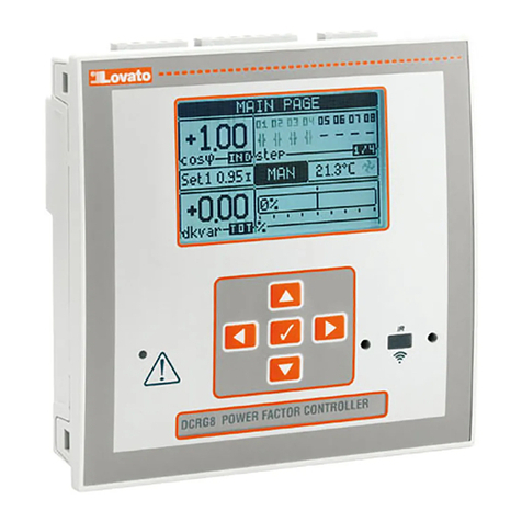
Auf dem alphanumerischen Display wird die manuelle Betriebsart außer
mit dem entsprechenden Symbol auch mit der Anzeige MAN kenntlich
gemacht. Durch Drücken auf MODE kann wie gewohnt durch die
anderen Messungen geblättert werden.
Solange das alphanumerische Display auf MAN eingestellt ist, können
die Stufen manuell aktiviert/deaktiviert werden. Zur Auswahl einer Stufe
die Tasten ▲oder ▼verwenden. Die ausgewählte Stufe ist am
schnellen Blinken zu erkennen.
Auf MODE drücken, um die ausgewählte Stufe ein- oder auszuschalten.
Wenn die Wiedereinschaltzeit der ausgewählten Stufe noch nicht
abgelaufen ist, blinkt das Symbol MAN, um anzuzeigen, dass der
Vorgang angenommen wurde und so bald wie möglich ausgeführt wird.
Die manuelle Konfiguration der Stufen wird auch bei Ausfall der
Netzspannung beibehalten. Sobald das Gerät wieder mit Spannung
versorgt wird, wird der ursprüngliche Zustand der Stufen wieder
hergestellt.
Stufe auswählen Stufenstatus ändern
MAN and AUT Modes
The icons AUT and MAN indicate the operating mode automatic or
manual.
For manual mode, press the MAN button for 1 sec in a row.
For automatic mode, press the AUT button for 1 sec in a row.
The operating mode remains stored even after removing and
reapplying the power supply voltage.
MAN Mode
When the unit is in manual mode, you can select one of the steps and
manually connected or disconnect it.
In addition to the specific icon, the alphanumeric display shows MAN
in order to highlight the manual mode condition. Press MODE to view
the other measurements as usual.
While the display shows MAN, it is possible to select the step to be
switched on or off. To select a step, use the ▲or ▼buttons. The
selected step will flash quickly.
Press MODE to activate or deactivate the selected step.
If the selected step has not yet exhausted the reconnection time, the
MAN icon will flash to indicate that the transaction has been accepted
and will be conducted as soon as possible.
Manual configuration of the steps is maintained even when the power
supply voltage is removed. When the power returns, the original state
of the steps is restored.
Select step Change step status
Betriebsmodus AUT
Im Automatikbetrieb berechnet das Gerät selbst die optimale
Konfiguration der Stufen zum Erreichen des vorgegebenen cos .
Das Auswahlkriterium berücksichtigt zahlreiche Variablen wie: die
Leistung der einzelnen Stufen, die Schalthäufigkeit, die
Gesamtnutzungsdauer, die Wiedereinschaltzeit, usw.
Das Gerät zeigt das bevorstehende Ein- bzw. Ausschalten der Stufen
durch Blinken ihrer Kennzahl an. Das Blinken kann unter Umständen
länger anhalten, wenn das Einschalten einer Stufe aufgrund der
Wiedereinschaltzeit (Entladezeit des Kondensators) nicht möglich ist.
Damit das Gerät eine automatische Korrektur durchführt, muss eine
durchschnittliche Blindleistungsanforderung (Delta-kVAr) vorliegen, die
um 50% größer als die kleinste Stufe ist, und der gemessene Wert cos
muss vom Sollwert abweichen.
UT Mode
In automatic mode, the controller calculates the optimum configuration
of capacitor steps in order to reach the set cos .
The selection criteria takes into account many variables such as: the
power of each step, the number of operations, the total time of use,
the reconnection time, etc.
The controller displays the imminent connection or disconnection of
the steps with the flashing of their identification number (left). The
flashing can last in cases in which the insertion of a step is not
possible due to the reconnection time (discharge time of the
capacitor).
The device initiates automatic corrections when there is an average
reactive power request (delta-kvar) higher than 50% of the smallest
step, and the measured cosphi is different from the setpoint.
Messungen
Der DCRL8 stellt mehrere Messungen bereit. Diese werden zusammen
mit dem aktuellen cos, der immer auf dem Hauptdisplay angezeigt
wird, auf dem alphanumerischen Display angezeigt.
Mit der Taste MODE kann nacheinander durch die Messungen
geblättert werden.
Wenn 30 Sekunden lang keine Tasten betätigt werden, kehrt die
Anzeige automatisch zu der mit Parameter P.47 vorgegebenen Default-
Messung zurück.
Wenn P.47 auf ROT eingestellt ist, werden die Messungen automatisch
alle 5 Sekunden nacheinander angezeigt.
Am Ende der Liste mit den Messungen kann durch Ändern des Werts
von P.19 der cos-Sollwert eingestellt werden.
Measures
The DCRL8 provides a set of measurements displayed on the
alphanumeric display, in conjunction with the current cosphi that is
always displayed on the main display.
Press the MODE key to scroll through the measures in rotation.
After 30 seconds without pressing any buttons, the display
automatically returns to the default measurement defined by P.47.
If P.47 is set on the ROT, then the measures rotate automatically
every 5 seconds.
At the bottom of the list of measures it is possible to set the setpoint of
the cosphi, acting on the same value set with P.19.
Below is a table with the measurements displayed.
▼
MODE
▲
▼
MODE
▲
nzeige
Betriebsart
TEST
Gesamtzahl
der Stufen
Firmware-
version
Variante des
Gerätemodells
Indication of
TEST mode
Total number
of steps
Firmware
revision
Model
variant
Symbol
Betriebsart
MAN
Stufen
eingeschaltet
In MAN insgesamt
eingeschaltete
kVA
nzeige
manuelle
uswahl
MAN mode
icon
Connected
steps
Tot kvar
inserited in
MAN
Manual step
selection
enabled
