MHIT301A0202.doc 29/05/2006 P 1 / 6
MULTIMETRO DIGITALE DIGITAL MULTIMETER
DMK26 DMK26
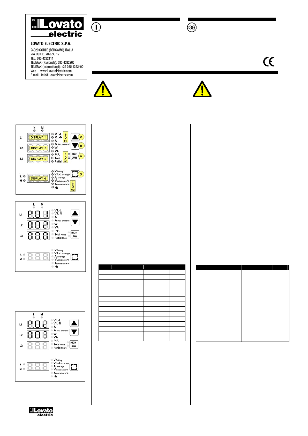
Esempio impostazione rapporto TA:
TA 1000/5A settare P01=200
Example of CT ratio programming:
With 1000/5A CT, set P01 to 200.
Esempio impostazione tempo filtro
average 3.
Example of average filter 3 setting
DESCRIZIONE
•Alimentazione da batteria 12…24VDC. Studiato in
particolare per il settore dei gruppi elettrogeni, è in
grado di sopportare per 500ms l’abbassamento di
tensione, dovuto all’avviamento del motore
•4 display a LED per una ottima leggibilità.
•Semplicità di installazione e configurazione.
•Misure in vero valore efficace (TRMS).
•47 misure con funzioni di analizzatore di potenza.
•Memorizzazione di massimi e minimi.
•Misura della tensione di batteria 9…38VDC.
IMPOSTAZIONE DEI PARAMETRI
•Premere contemporaneamente i pulsanti C e D per 5
secondi per accedere alla impostazione
•Sul DISPLAY 1 comparirà P.01 ad indicare che e’
stata selezionata l’ impostazione del parametro 01.
•Sui DISPLAY 2 e 3 verrà visualizzato il valore attuale
del parametro.
•I tasti A e B aumentano / diminuiscono il valore del
parametro attualmente selezionato.
•I tasti C e D selezionano il parametro da P.01 a P.11.
•Premere il tasto D per 2 secondi per memorizzare ed
uscire dalla impostazione.
•Normalmente per rendere operativo lo strumento e’
necessario impostare il solo parametro P.01,
lasciando gli altri parametri al valore di default.
TABELLA PARAMETRI
PAR Funzione Range Default
P.01 Rapporto TA 1.0 ÷ 2000 1.0
P.02 Filtro average 1÷ 10 3
P.03 Tipo di
collegamento
1 fase
2 fasi
3 fasi
3 fasi bil.
1ph
2ph
3ph
3bl
3ph
P.04 Frequenza Aut – 50 – 60 Aut
P.05 Preset display 1-2-3 1÷9 1
P.06 Preset display 4 1÷6 1
P.07 Ritardo Preset Off÷250 sec 60
P.08 Soglia di tensione 0ff÷100.0 Off
P.09 Soglia di corrente 0ff÷100.0 Off
P.10 Preset parziale Off÷60000 Off
P.11 Tempo integrazione
A Max demand
1 ÷ 60min 15min
Nota! Il sistema di calcolo del DMK è in grado di
gestire valori di potenza totale sino a 40MVA.
• Per impostare il valore del parametro P.01 vengono
utilizzati i DISPLAY 2 e 3 insieme in modo da
visualizzare un valore da 5 cifre + 1 decimale.
• P.02 permette di variare l’effetto stabilizzante che la
funzione average applica alle misure.
• P.03 deve rispecchiare il collegamento del
multimetro (vedere il capitolo ‘Schemi inserzione’).
Con collegamento trifase bilanciato è necessario che
venga inserito un solo TA sulla fase L1.
Ad eccezione delle tensioni, tutte le altre misure
sulle fasi L2, L3 sono uguali alla fase L1.
DESCRIPTON
•Battery power supply 12…24VDC. Designed to meet the
technical requirements of generating set applications.
Able to withstand dropouts during cranking (500ms
micro-breaking immunity)
•4 LED displays for excellent readability
•Easy to install and configure
•RMS measures (TRMS)
•47 measures and power analyser functions
•Maximum and minimum measure recording
•Battery (supply) voltage measure range 9…38VDC.
PARAMETER SETTING
•Press keys C and D together for 5 seconds to access
the setting facility.
•DISPLAY 1 will show P.01 meaning that the setting for
parameter 01 has been chosen.
•With DISPLAYS 2 and 3, the value programmed for the
selected parameter is viewed.
•Keys A and B respectively increase and decrease the
value of that selected parameter.
•With keys C and D, parameters P.01 to P.11 can be
selected.
•Press key D for 2 seconds to store the setting and exit.
•Normally, to set the device working, parameter P.01
only must be set, eventually leaving the others at the
default value.
PARAMETER TABLE
PAR Function Range Default
P.01 CT ratio 1.0 - 2000 1.0
P.02 Average filter 1 - 10 3
P.03 Type of
connection
1 phase
2 phases
3 phases
3 bal. phases
1ph
2ph
3ph
3bl
3ph
P.04 Frequency Aut – 50 – 60 Aut
P.05 Display 1-2-3 preset 1 - 9 1
P.06 Display 4 preset 1 - 6 1
P.07 Preset delay Off - 250 sec 60
P.08 Voltage threshold 0ff - 100.0 Off
P.09 Current threshold 0ff - 100.0 Off
P.10 Partial preset Off - 60000 Off
P.11 A Max demand
integration time
1 - 60min 15min
Note! The DMK calculating system can handle total power
values up to 40MVA.
•To set the value of P.01 parameter, a 5-digit +1-decimal
value is viewed using DISPLAYS 2 and 3 together.
•P.02 consents to change the stabilising effect of the
average function applied to the measures.
•P.03 must match the multimeter connection; refer to the
“wiring diagrams” section.
With balanced three–phase connection, one CT only
must be connected on L1 phase.
Except for voltage values, all the other measures on L2
or L3 phase are the same as L1 phase.
ATTENZIONE!! Questi apparecchi devono
essere installati da personale qualificato, nel
rispetto delle vigenti normative impiantistiche, allo
scopo di evitare danni a persone o cose.
I prodotti descritti in questo documento sono
suscettibili in qualsiasi momento di evoluzioni o di
modifiche.
Le descrizioni ed i dati a catalogo non possono
ertanto avere alcun valore contrattuale
WARNING! This equipment is to be installed by
trained personnel, complying to current standard,
to avoid damages or safety hazards. Products
illustrated herein are subject to alteration and
changes without prior notice.
Technical data and descriptions inthedocumentation
are accurate, to the best of our knowledge, but no
liabilities for errors, omissions or contingencies
arising therefrom are accepted.


