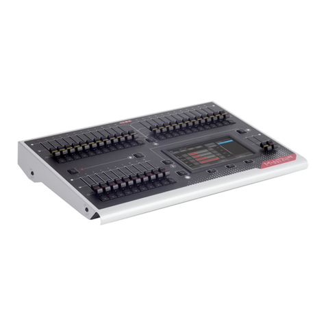
LSC Atom 12/24 User manual

LIGHTING CONTROL DESK
OPERATOR MANUAL
Software Version 1.21
January 2002
L.S.C. Lighting Systems (Aust) Pty. Ltd.
A.C.N. 090 801 675
7 University Place, Clayton,
Victoria, 3168 Australia
Tel: +61 39561 5255
Fax: +61 39561 5277
Email: [email protected]
Web site: www.lsclighting.com.au

QUICK REFERENCE
Note: When the RECORDING or PREVIEW/EDITING, all Submasters flash twice, then Submasters
containing Scenes are lit, Submasters containing Chases flash and empty Submasters are not lit..
RECORD A SCENE
To record the current output as a Scene into the current page, press: [RECORD], (SCENE)
[S/A] (Scene number) (any of the RED preset Solo/Assign keys)
GRAB THE OUTPUT IN GRAB MASTER
To record the current output into the Grab master, press: [RECORD], (SCENE)
[S/A] (Grab master)
RECORD A CHASE
To record a Chase in the current page, press: [RECORD], (CHASE)
[S/A] (Chase number) (any of the RED preset Solo/Assign keys or the Grab S/A key)
Each step of a Chase consists of a snapshot of the output which is taken as that step is “added”.
Create the look for the first step on the output, then to record it as the first step, press;
[RECORD], (ADD STEP)
Create the next look on the output.
To record this step, press;
[RECORD], (ADD STEP)
Continue to create and record steps as above.
When all steps have been recorded, complete the chase by pressing;
[RECORD], (END CHASE)
PLAYBACK A CHASE or SCENE
If not already in SCENE mode, press [MODE] until the “Scene” mode LED lights.
Fade up the Submaster containing the recorded chase or scene and also the Red preset master.
CONTROLLING A CHASE
To control a chase you must edit that chase.
Press [PREVIEW/EDIT]
[S/A] (Chase number)
•To control the RATE rotate the edit wheel.
•To BASS STEP the chase (Sound To Light), set the rate below 0 BPM. (See also “BASS LEVEL”, below).
•To change the FADE between steps, press [FUNCTION] until IN & OUT light, then rotate the edit wheel.
•To change the MODE or DIRECTION use the 3 keys below the Edit wheel as described below.
KEYS ACTION
[STOP/STEP] STOPS a running chase.
STEPS a stopped chase.
[>](Forward) STARTS a stopped chase and runs it forward.
Changes the DIRECTION of a reverse running chase (runs it forward).
SNAPS a forward running chase to the next step.
[<] (Reverse) STARTS a stopped chase and runs it backwards.
Changes the DIRECTION of a forward running chase (runs it backwards).
SNAPS a backward running chase to the next step.
Hold [>], Tap [<] Selects BOUNCE mode.
Hold [<], Tap [>] Also selects Bounce mode.
[>] Deselects Bounce mode (runs forward).
[<] Deselects Bounce mode (runs reverse).
Hold [Stop/Step], Tap [>] Selects SINGLE SHOT mode.
[>] Runs a Single Shot in the forward direction (see also below).
[<] Runs a Single Shot in the reverse direction (see also below).
Hold [Stop/Step], Tap [<] De-selects single shot mode.
•When finished, press [PREVIEW/EDIT] (to de-select it). The latest settings are automatically saved.
In normal mode (not in Preview/Edit);
•To run a chase that has been set in single shot mode, press; [S/A] (Chase number).
•To adjust the BASS STEP audio level, press [FUNCTION] tap [S/A 12] (BASS LEVEL), then rotate the edit
wheel. When the chase is satisfactorily stepping to the beat, press; [YES] to save the setting. The STEP
LED flashes and the chase steps on each beat of the music. (See also “BASS STEP”, above).

LSC Lighting Systems (Aust) Pty Ltd 1
CONTENTS
QUICK REFERENCE________________IFC
1.0 INTRODUCTION __________________2
1.1 FEATURES ________________________2
1.2 OPTIONS __________________________3
1.3 CARING FOR YOUR ATOM ___________3
1.4 LABELLING YOUR ATOM_____________3
1.5 MODELS __________________________3
1.6 KEYSTROKE TERMINOLOGY _________4
1.7 SOFTWARE________________________4
2.0 GETTING CONNECTED ____________5
2.1 MAINS INPUT ______________________5
2.2 DIGITAL OUTPUT (DMX 512/1990) _____5
2.3 VIDEO MONITOR ___________________5
2.4 SWITCHING ON ____________________5
3.0 LAYOUT_________________________6
4.0 MODES OF OPERATION __________10
4.1 OVERVIEW _______________________10
4.2 PRESET MODE ____________________10
4.3 WIDE PRESET MODE_______________11
4.4 SCENE MODE _____________________11
5.0 QUICKSTART TUTORIAL__________12
5.1 RESET ___________________________12
5.2 CONTROLLING LIGHTS _____________12
5.3 RECORDING A SCENE______________14
5.4 REPLAYING A SCENE ______________14
5.5 RECORDING A CHASE______________15
5.6 REPLAYING A CHASE ______________15
6.0 MEMORY STRUCTURE ___________16
6.1 MODE/PAGE FREEZE_______________16
7.0 FADE TIMES & CHANNEL LEVELS__17
7.1 OVERVIEW OF FADE TIMES _________17
7. 2 CHANNEL CAPACITY ______________17
8.0 SCENES________________________18
8.1 OVERVIEW _______________________18
8.2 RECORDING SCENES ______________18
8.3 REPLAYING SCENES _______________ 19
8.4 PREVIEWING &/OR EDITING A SCENE 20
8.5 COPYING A SCENE ________________21
8.6 DELETING A SCENE________________21
9.0 CHASES________________________22
9.1 OVERVIEW _______________________22
9.2 RECORDING CHASES ______________22
9.3 REPLAYING CHASES_______________ 24
9.4 PREVIEWING &/OR EDITING A CHASE 26
9.5 COPYING A CHASE ________________ 27
9.6 DELETING A CHASE________________ 27
10.0 GRAB MASTER ________________ 28
10.1 OVERVIEW ______________________ 28
10.2 GRAB MASTER AS A GRAB MASTER_ 28
10.3 GRAB MASTER AS A SCENE MASTER 28
10.4 GRAB MASTER AS A CHASE MASTER 29
11.0 SOLO ________________________ 30
11.1 OVERVIEW ______________________ 30
11.2 ADD/KILL MODE __________________ 30
11.3 SOLO FADER ____________________ 30
12.0 PATCH _______________________ 31
12.1 OVERVIEW ______________________ 31
12.2 ENABLING PATCH SELECTION _____ 31
12.3 PATCHING DIMMERS TO CHANNELS 32
13.0 UTILITIES _____________________ 33
13.1 RESET __________________________ 33
13.2 INVERT YELLOW PRESET MASTER _ 33
13.3 PRINT___________________________ 34
13.4 VIDEO OUTPUT __________________ 34
13.5 DISK____________________________ 35
13.6 DIAGNOSTICS ___________________ 36
14.0 REAR PANEL __________________ 37
14.1 FUSES __________________________ 37
14.2 VGA OUTPUT (OPTIONAL) _________ 37
14.3 EXPANSION PORT (RS 232C)_______ 37
14.4 DESK LAMP CONNECTOR _________ 37
14.5 ANALOGUE OUTPUT CONNECTORS_ 37
14.6 MODE SWITCHES ________________ 37
14.7 AUDIO INPUT ____________________ 37
15.0 APPENDIX A 'DMX 512'__________ 38
15.1 DMX512/1990 ____________________ 38
15.2 CONTROLLING ANALOGUE DIMMERS38
15.3 TYPICAL DMX512 APPLICATIONS.___ 39
16.0 APPENDIX B:ANALOGUE OUTPUTS40
17.0 APPENDIX C “TERMINOLOGY”___ 41
18.0 INDEX ________________________ 43
Atom Operator Manual Introduction
LSC Lighting Systems (Aust) Pty. Ltd. 2
1.0 INTRODUCTION
The Atom is a simple to use yet powerful lighting control desk that is suited to a wide range of applications. It
is available in the 12/24 channel model and the 24/48 channel model, both of which have similar features and
vary only in the number of channels and Submasters that they support.
Atom 12/24 Atom 24/48
1.1 Features
The Atom incorporates the following features;
•Manual faders for all channels with associated Solo keys.
•Red, Yellow and Grab Preset masters with associated Solo keys.
•Yellow Preset master may be inverted.
•“Preset”, “WIDE” preset and “Scene” modes of operation.
•In Scene mode, the red faders become Submasters that may be used for scenes or chases.
•9 pages of memory for the Submasters.
•Separate In (up) and Out (down) fade times (0 to 120 seconds).
•Scene Fade Times can be derived from the Time Faders or from Memory.
•Solo level fader, with associated Add or Kill mode key.
•Large storage capacity for Scenes and Chases.
ATOM 12/24 ATOM 24/48
Channels -Preset Mode 12 24
Channels -Wide Mode 24 48
Submasters -Scene Mode 12 24
Pages of memory 99
Scenes up to 108 up to 216
Chases up to 108 up to 216
Steps per chase 99 99
Active chases 13 25
•Extensive Recording Editing and Previewing facilities for Scenes & Chases.
•Utilises “battery backed up” memory.
•User prompts are scrolled on the display and active keys flash to make operations simple.
•Information may be displayed on a VGA monitor (optional), Video Terminal or Personal Computer.
•Memory contents may be down loaded to a serial printer or a computer
•DMX 512/1990 output signal.
•Inbuilt Softpatch.
•Power supply is user selectable, 85−130 volts or 170−260 volts.

Atom Operator Manual Introduction
LSC Lighting Systems (Aust) Pty. Ltd. 3
1.2 Options
•3.5” PC compatible floppy disk drive for show back-up and transportation.
•VGA video monitor output (monitor not included).
•12V halogen gooseneck desk lamp.
•Analog output(s) in a variety of connectors (+ve or -ve, 0 to 10 volt) to drive analog dimmers.
•Flight case.
NEW FEATURES
Version 1.1
•Chases may have timed crossfades between steps. As well as providing a useful variation for traditional
chases, it is invaluable when controlling moving lights.
•VGA video output provides OUTPUT, PREVIEW and SOFTPATCH screens plus quick reference HELP
pages.
•Shows recorded on floppy disk are interchangeable between both models of the Atom.
•Complies with relevant regulations.
Version 1.2
•Chase stepping may be synchronised to the bass beat of an audio input signal (BASS STEP).
1.3 Caring For Your Atom
The Atom is manufactured from quality components and will give many years of service if you take some
basic precautions.
•Do not allow any liquids or foreign objects to enter the Atom. If any liquids are spilt onto the Atom,the
inside should be cleaned and dried as soon as possible. Only suitably qualified personnel should remove
the covers and perform any such maintenance.
•Do not apply excessive force to any of the controls. Spare parts and service are available from your LSC
agent, but prevention is better than cure.
•When connecting any devices to the Atom, make sure that all connections are correct before switching on
the power. If any doubt exists, obtain the assistance of qualified personnel.
•If your Atom is to be used "on the road", you should use a flight case to protect the desk. Transport the
Atom with all faders in the fully down position. This gives the faders maximum protection from damage.
•The Atom contains a replaceable lithium battery.
CAUTION
Danger of explosion if battery is incorrectly replaced.
Replace only with the same or equivalent type recommended by the manufacturer.
Dispose of used batteries according to manufacturer’s instructions.
1.4 Labeling Your Atom
Areas are provided below the faders for you to write identifying labels. To prevent permanent marking of your
Atom, LSC recommends that you write place strips of “write on” tape in these areas.
1.5 Models
This manual covers both models of the Atom. They are the:
Atom 12/24 and Atom 24/48
The Atom may be operated in any of three modes and the model numbers above refer to the number of
channels that may be controlled with individual channel faders in the different modes.
See the “MODES OF OPERATION” chapter for details.
ATOM 12/24
In “Preset” and “Scene” modes, there is an individual channel fader for channels 1 to 12.
In “WIDE preset” mode, there is an individual channel fader for every channel, 1 to 24.
ATOM 24/48
In “Preset” and “Scene” modes, there is an individual channel fader for channels 1 to 24.
In “WIDE preset” mode, there is an individual channel fader for every channel, 1 to 48.

Atom Operator Manual Introduction
LSC Lighting Systems (Aust) Pty. Ltd. 4
At any point in this manual where the model affects the operational description, the text will describe the 12/24
channel model followed by the other model in brackets.
For example,
“The Yellow preset has faders for channels 1 to 12 (24)”.
In both models, the lower half of the channels are referred to as the low channels and the upper half are
referred to as the high channels
For example, in an Atom 12/24, channels 1 to 12 are the low channels and channels 13 to 24 are the high
channels.
1.6 Keystroke Terminology
Certain keystroke terminology is used throughout this manual to describe the particular operations being
undertaken. Any text enclosed in these symbols, [ ] , refers to when that particular key needs to be pressed.
For example; Press [PAGE], means to press the page key located near the top right of the Atom.
SOLO/ASSIGN keys are often abbreviated to S/A. If the key to be pressed is a SOLO/ASSIGN key (of which
there are many) then it will be identified by naming it as follows;
[SOLO/ASSIGN] (Name) or the shortened version, [S/A] (Name).
For example;
Press [S/A] (GRAB), refers to the Grab master's SOLO/ASSIGN key.
or; Press [S/A] (5), refers to the channel 5 SOLO/ASSIGN key.
Any information that appears on the 7 segment displays is printed in “quotes”.
SECONDARY FUNCTIONS
•Red preset S/A keys have secondary functions that are activated by holding down the FUNCTION key
and tapping the S/A key. These secondary functions are printed on the front panel below their S/A keys.
For example; Press and hold [FUNCTION], tap [S/A] (PRINT), refers to the SOLO/ASSIGN key in the
bottom left corner of the Atom.
•Some Yellow preset solo keys have hidden secondary functions that are activated by holding down the
FUNCTION key and tapping the S/A key. These secondary functions are not labelled but are described in
the “Diagnostics” section of the “UTILITIES” chapter.
•There are 3 RECORD keys described as:
[RECORD] (Scene) [RECORD] (Chase) [RECORD] (Copy)
These keys have secondary functions that become active when recording or editing Chases. They are
respectively;
[RECORD] (Add Step) [RECORD] (End Chase) [RECORD] (Delete Step)
•The <and >keys below the Edit wheel have secondary functions in that they are used to answer either
“Yes” or “No” respectively to questions that appear on the display when you are performing certain
actions. They are typically used to confirm the action that you have selected.
For example;
To perform a SYSTEM RESET;
Press and hold [FUNCTION], tap [S/A] (RESET), release [FUNCTION].
The display asks “System Reset ?”. Press [YES]
1.7 Software
LSC has a policy of continuous improvement of its products. As the Atom is a computerised lighting desk, its
software is subject to this policy as new features are added and existing features improved.
The software version of your Atom is momentarily displayed on the LED display when the Atom is switched
on. This manual covers software version 1.2
The operating software of the Atom and the contents of this manual are copyright.
All Trademarks referred to in this manual are the registered names of their respective owners.
Whilst every care is taken in the preparation of this manual, LSC takes no responsibility for any errors or
omissions.

Atom Operator Getting Connected
LSC Lighting Systems (Aust) Pty. Ltd. 5
2.0 GETTING CONNECTED
2.1 Mains Input
An IEC mains input socket is located on the rear panel and a mains lead is provided. The Atom will operate
from a variety of mains voltages. Before switching on, ensure that the voltage setting is correct for your local
mains supply. The voltage setting is indicated in a window on the fuse holder located in the base of the mains
input socket.
•The 120 position enables the Atom to operate on a voltage range from 85 to 130 Volts AC, 50 or 60 cycles
per second (Hz)
•The 240 position enables the Atom to operate on a voltage range from 170 to 260 Volts AC, 50 or 60
cycles per second (Hz)
If the setting is incorrect, remove the power lead then squeeze the tabs on the side of the fuse holder and
slide it out. Rotate the voltage select insert to reveal the correct voltage setting in the window. Replace the
holder.
Plug the mains lead into the MAINS INPUT socket and connect it to a source of mains power.
2.2 Digital Output (DMX 512/1990) Connector
Connect a data cable from the DMX512 output of the Atom to the DMX512 input of your equipment (dimmers)
and set the required channel address on your equipment.
Note: DMX512/1990 together with some typical setups and address settings are described in
“Appendix A” at the end of this manual.
Hint: The Atom provides control for 24 (48) channels, however by utilising the Atom’s softpatch
functions, you can control any dimmer output number from 1 up to 99. Refer to the “Patch” chapter
for details.
2.3 Video Monitor
If your Atom is fitted with the VIDEO option, connect a VGA (or better) computer monitor to the 15 pin
“VIDEO” connector on the rear of the Atom.
2.4 Switching On
At this point, with the mains power and DMX connected, the Atom is ready to be operated. Simply switch on
the “POWER” switch located beside the mains input connector. The inbuilt neon in the switch will glow and the
Atom will commence its startup procedures. After briefly displaying the opening message, the Atom will
commence operating in exactly the same state that it was in when it was last switched off. All the scenes,
chases, patches etc will be as they were.
Hint; If you are starting a new lighting session, LSC recommends that you perform a “TOTAL RESET”
of the Atom. This will erase all previously recorded memories and will prevent you being confused by
previous recordings and settings. See the “QUICKSTART TUTORIAL” or “UTILITIES” chapters for
details.
You are now ready to start controlling your lights as described in the “QUICKSTART TUTORIAL” chapter, but
before you do, the next chapter gives you a guided tour of the front panel controls of the Atom and this is
followed by a brief description of the three modes of operation.

Atom Operator Manual Layout
LSC Lighting Systems (Aust) Pty. Ltd. 6
3.0 LAYOUT
The front panel of the Atom is divided into two main areas;
•The fader section on the left.
•The mastering and recording section on the right.
Note: The size of the fader bank area varies depending upon the model, as it provides a fader for every
channel (24 or 48). The mastering and programming section is identical for both models.
FUNCTION STOP
STEP
SOLO
ASSIGN (YES) (NO)
EDIT
SCENE CHASE COPY
RECORD
SCENE
CHANNEL
CHASE
DIMMER
STEP
RATE (BPM)
OUT(S)
IN(S)
LEVEL
(ADD STEP) (DELETE STEP)(END CHASE)
PAGE
MODE
PRESET
WIDE
SCENE
FREEZE
><
SOLO
ASSIGN
PREVIEW
EDIT
MASTERS SECS LEVEL
TIME
OADD
KILL
GRABR Y
FUNCTION: PRINT 1:1
PATCH SOFT
PATCHCLEAR
PATCH HELP
(
VIDEO
)
DISK PREFS RESET BASS
LEVEL
IN OUT
120 120
00
1
2
3
4
5
6
6
8
7 9
10 11
12
Front panel layout of an Atom 12/24.
Many of the keys listed below perform more than one function. The current function depends upon what the
operator is doing at the time. Each of these different functions is described under the relevant key below.
1. YELLOW PRESET FADERS
Control the levels of channels 1 to 12 (24) respectively.
2. YELLOW PRESET MASTER
•Controls the overall level of the Yellow preset faders (the low channels).
•In WIDE Preset mode, it controls the overall level of the single wide preset consisting of the Yellow preset
faders (the low channels) and the Red preset faders (the high channels).
3. MODE KEY
Selects the current function for the RED preset faders. The choices are;
•PRESET mode.
•WIDE Preset mode.
•SCENE mode.
Note; In WIDE Preset mode, both the WIDE and PRESET indicators are lit.
4. RED PRESET FADERS
The Red bank of faders have different functions depending upon the current “MODE” of the Atom as selected
by the MODE key.

Atom Operator Manual Layout
LSC Lighting Systems (Aust) Pty. Ltd. 7
•PRESET mode. The Red bank of faders control the levels of channels 1 to 12 (24). (A duplicate of the
Yellow preset).
•WIDE Preset mode. The Red bank of faders control the levels of channels 13 (25) to 24 (48). (The high
channels).
•SCENE mode. The Red bank of faders become SUBMASTERS. Each Submaster can control the level of a
recorded Scene or Chase or it may be empty (does nothing). There are 9 pages of memory for the
Submasters and the function of each submaster depends upon the contents of the currently selected page.
You determine what each page contains when you record (or copy) scenes or chases into them.
5. RED PRESET MASTER
•In PRESET mode, it controls the overall level of the Red preset (the low channels).
•In WIDE Preset mode it has no function.
•In SCENE mode it controls the overall level of the Red preset (Scenes or Chases).
6. SOLO/ASSIGN (S/A) KEYS
Below each fader in the fader section is a SOLO/ASSIGN key with an integral red indicator LED.
As their name implies, these are multi purpose keys.
They may be used to:
•SOLO (flash or bump) the contents of their particular fader, be it a channel, chase or a scene. (See also
SOLO level and ADD/KILL key below).
•Run a chase if the chase is in “Single Shot” mode.
•Provide a NUMERIC ENTRY function. When the “number” of a channel, scene, chase, etc needs to be
entered, the appropriate Solo/Assign key “number” is pressed. To assist you in making a selection, valid
keys will flash when an entry is required.
•In conjunction with the FUNCTION key, select various secondary functions such as PRINT, 1:1 PATCH etc
as indicated below the RED S/A keys.
NUMBERING
Between each fader in the Yellow fader bank and its associated S/A key is a number that indicates the
channel that the fader and S/A key control.
Between each fader in the Red fader bank and its associated S/A key are two numbers;
•In PRESET mode the LARGER font indicates the channel number of the fader and S/A key.
•In WIDE Preset mode the SMALLER font indicates the channel number of the fader and S/A key.
•In SCENE mode the LARGER font indicates the number a particular SCENE or CHASE.
•The
SMALLER font also indicates channel numbers when editing scenes or chase steps, when viewing
channel levels on the SOLO/ASSIGN key LED indicators (refer below) or when “Softpatching”.
The LED indicators in each S/A key are also multi purpose.
CHANNEL LEVEL INDICATORS:
The brightness of each indicator is proportional to the level of its channel. The yellow bank indicates the level
of the low channel numbers and the red bank indicates the level of the high channel numbers (printed in the
SMALLER font).
•In normal operation, they indicate the level of their particular channel at the output of the Atom.
•In Preview mode they indicate the level of their particular channel in the Scene, Grab or Step of a Chase
that is being previewed.
VALID ENTRY KEY INDICATORS:
When you are required to make a numeric entry or Secondary Function selection, only valid keys will be active
and their LED indicators will light to indicate to you that an entry is required.
FADE IN PROGRESS INDICATORS:
The indicator for with each Submaster (Scene mode) flashes slowly whilst a timed fade is in progress.
7. PRESET MASTER SOLO/ASSIGN KEYS
Used to SOLO (flash or bump) the contents of their particular master. (See also SOLO level and ADD/KILL key
below). The brightness of their LED indicators shows the level of the master at the output of the Atom. It also
will flash slowly whilst a timed fade is in progress.
8. GRAB MASTER
Controls the overall level of the contents of the Grab master. This may be a Grab, a Scene or a Chase.

Atom Operator Manual Layout
LSC Lighting Systems (Aust) Pty. Ltd. 8
9. GRAB SOLO/ASSIGN KEY
Solo's (flashes or bumps) the contents of the Grab master. (See also SOLO level and ADD/KILL key below).
In conjunction with the RECORD (SCENE) key, it performs the “GRAB” function, or selects the grab master
when required for other various functions. The brightness of its LED indicator shows the level of the Grab
master at the output of the Atom. It also will flash slowly whilst a timed fade is in progress.
10. IN AND OUT TIME FADERS
Control the IN and OUT fade times of the Preset masters and the Grab master. They may also be individually
assigned to control the IN or OUT fade times of any scene. The current time setting of each fader is shown on
the display when its fader is moved or presses of the FUNCTION key will toggle through the two time settings.
11. SOLO LEVEL MASTER
Sets the level to which any Channels, Submasters, Preset masters, or the Grab master, will be flashed when
their respective SOLO/ASSIGN key is pressed.
12. ADD/KILL KEY
Toggles the Add/Kill mode between “Add” and “Kill” as shown by a red indicator in the Add/Kill key.
•In ADD mode, when a SOLO/ASSIGN key is pressed, the channels that are being flashed will come on (at
the level of the SOLO level master), and the normal output of the Atom is not affected.
•In KILL mode, when a SOLO/ASSIGN key is pressed, the channels that are being flashed will come on (at
the level of the SOLO level master), and the normal output of the Atom will be killed (blacked out), leaving
only the channels that are being flashed on stage.
Note: Multiple Solo/Assign keys may be pressed at the one time.
FUNCTION STOP
STEP
(YES) (NO)
EDIT
SCENE CHASE COPY
RECORD
SCENE
CHANNEL
CHASE
DIMMER
STEP
RATE (BPM)
OUT(S)
IN(S)
LEVEL
(ADD STEP) (DELETE STEP)(END CHASE)
PAGE
MODE
PRESET
WIDE
SCENE
FREEZE
><
PREVIEW
EDIT
13
14
15
16 17
19
20
21
22
23 24
25
18
RECORD & PREVIEW/EDIT Section (common to both models).
13. PAGE KEY
•In SCENE mode it is used to select the current page (1 to 9) of memory that is loaded into the Submasters.
•When recording, previewing or editing scenes or chases, it is used to select the required page (1 to 9) for
the scene or chase.
•It is also used to Preview channel levels (Page C) and to Preview/Edit the patch when enabled (Page P).
Repeated presses of the Page key will step through the pages. To directly select a page;
Hold [PAGE] then tap [S/A] (Page Number) or [S/A] (Red 10) for page “C” or [S/A] (Red 11) for page “P”.
Pages C and P only appear when in preview mode.
14. PAGE DISPLAY
Displays the page number selected by the Page key.
15. RECORD SCENE (ADD STEP) KEY
Used to record the current output into a Scene, or into the Grab master or to Add (record) steps in a chase.
16. RECORD CHASE (END CHASE) KEY
•Used to select RECORD CHASE mode.
•Also used to complete the recording of a chase when all the desired steps have been added.

Atom Operator Manual Layout
LSC Lighting Systems (Aust) Pty. Ltd. 9
17. RECORD COPY (DELETE STEP) KEY
•Used to copy scenes or chases to different Submasters and/or Pages or to (or from) the Grab master.
•Also used to delete steps in a chase when recording or editing.
18. SEVEN SEGMENT DISPLAY AND LEDS
The display is used to scroll messages and prompts and to show numbers. The nine labelled LEDS beside the
display are used to define the numbers shown on it. For example;
•If the CHANNEL LED is lit, then the number displayed is a channel number.
•If the CHANNEL and LEVEL LEDs are lit, then the number displayed is a channel level (and the channel
number will be indicated by its S/A key flashing).
Comprehensive information including the messages and prompts is also shown on the optional VGA screen.
19. PREVIEW/EDIT KEY
•When pressed, it places the Atom in Preview /Edit mode. You may then choose to Preview or Edit any
Channel, Scene, Chase, the Patch (if selected) or the contents of the Grab master.
•Double clicking [PREVIEW/EDIT] shows the current output on a video display (if connected).
20. FUNCTION KEY
•When pressed during normal operations, it causes the display to momentarily show the current time
settings of the time faders. One press momentarily shows the IN time and a second press (whilst the IN
time is still displayed) will change the display to the OUT time.
•When editing, it toggles through the various functions indicated on the column of LEDs above it.
•It accesses the secondary functions indicated below the red SOLO/ASSIGN keys. To perform secondary
functions; Press and hold [FUNCTION] then tap [S/A] (Secondary Function).
21. EDIT WHEEL
Continuously rotatable in either direction and can be used to:
•Set fade times when recording.
•Adjust the level of channels or set fade times when editing.
•Adjust chase RATE when recording or editing.
•Select dimmer numbers when softpatching.
22. EDIT WHEEL INDICATOR
•Lights when the Edit Wheel is active.
•When editing, it flashes quickly when a parameter is varied above its recorded value and flashes slowly
when a parameter is varied below its recorded value. It remains steady if the parameter is set back to its
previously recorded value.
23. > (YES) KEY
•Runs a chase in the FORWARD direction.
•Increments through the dimmer numbers when Softpatching.
•Answers “YES” to a request from the Atom.
24. < (NO) KEY
•Runs a chase in the REVERSE direction.
•Decrements through the dimmer numbers when Softpatching.
•Answers “NO” to a request from the Atom.
25. STOP STEP KEY
Used to STOP a chase or STEP a stopped chase.
Note; Combinations of keys 23, 24 and 25 are used to set and control various chase modes such as
bounce and single shot. See the “CHASE” chapter or the “QUICK REFERENCE” for details.

Atom Operator Manual Modes of Operation
LSC Lighting Systems (Aust) Pty. Ltd. 10
4.0 MODES OF OPERATION
4.1 Overview
The Atom has two banks of faders known as presets.
•The Yellow preset controls the levels of channels 1 to 12 (24).
•The Red preset has different functions depending upon the current “MODE” of the Atom as selected by the
MODE key. These modes are;
•PRESET mode. The Red preset controls the levels of channels 1 to 12 (24). (A duplicate of the Yellow
preset).
•WIDE Preset mode. The Red preset controls the levels of channels 13 (25) to 24 (48). (The high
channels).
•SCENE mode. The Red preset faders become SUBMASTERS and control the levels of Scenes or
Chases.
You may freely change modes at any time during your operation of the Atom and the current mode is always
shown by the red “LED” MODE indicators beside the MODE key.
Each mode has its particular advantage for different types of operations.
4.2 Preset Mode
Two identical presets (Yellow and Red) provide duplicate faders for the low channels, 1 to 12 (24). The output
of each preset is controlled by its own Preset master.
RED GRAB ADD/KILL
YELLOW PRESET
RED PRESET
PRESET
MASTERS
YELLOW
123456789101112
123456789101112
CHANNELS 1-12
CHANNELS 1-12
OUTPUT
Simplified block diagram of a 12/24 Atom in PRESET mode.
You create a lighting look by fading up your required channels on one of the colour coded presets and fading
up the same colour preset master. By keeping the other preset master faded down, another look can be
preset on the duplicate set of channel faders without the channels being revealed on stage. At the appropriate
time, the new look is revealed by fading up its Preset master whilst the first look is faded down with its Preset
master. The next look may now be prepared on the preset that has just been faded down.
The fade times of the preset masters are set by the IN and OUT time faders.
ADVANTAGE
This simple mode of operating is most useful in unrehearsed situations where the next “look” needs to be
created “on the fly”. The channel faders provide instant “hands on” control of any channel level.
DISADVANTAGE
Only the low channels can be controlled and any look that needs to be used at a later time must be manually
reproduced with the channel faders (unless you record the look that you create as a scene). (See “Scene
Mode” below).

Atom Operator Manual Modes of Operation
LSC Lighting Systems (Aust) Pty. Ltd. 11
4.3 Wide Preset Mode
Wide preset mode utilises both the red and yellow fader banks as a single manual preset of 24 (48) channels.
The yellow faders control the low channels and the red faders control the high channels. There is an individual
fader for every channel. The yellow preset master controls the total output of this single (wide) preset.
RED GRAB ADD/KILL
YELLOW PRESET
RED PRESET
PRESET
MASTERS
YELLOW
123456789101112
13 14 15 16 17 18 19 20 21 22 23 24
CHANNELS 1-12
CHANNELS 13-24
OUTPUT
Simplified block diagram of a 12/24 Atom in Wide preset mode.
As in Preset mode, you can “balance” the look that you are creating by adjusting the intensities of the
individual channels with their channel faders. You may fade this “look” up and down with the Yellow Preset
master and of course, you may use the In and OUT time faders to set the fade times.
ADVANTAGE
You have access to all of the channels that are available on the Atom. This is most useful when you are
RECORDING scenes as you can utilise all channels to create your scenes. (See “Scene Mode” below).
DISADVANTAGE
You do not have a second preset on which to create the next look although you can perform crossfades to
another “look” by utilising the Grab master as a “phantom” preset. See the “GRAB MASTER” chapter for
details.
4.4 Scene Mode
In Scene mode the faders of the red fader bank become Submasters containing scenes or chases
RED GRAB ADD/KILL
YELLOW PRESET
RED PRESET
PRESET
MASTERS
YELLOW
123456789101112
1234567891011
12
SUB MASTERS 1 - 12
CHANNELS 1 - 12
OUTPUT
Simplified block diagram of a 12/24 Atom in SCENE mode.
Scenes and chases can be recorded, previewed or edited whilst operating in any of the three modes but the
Red preset may only be used to replay scenes and chases in Scene mode.
ADVANTAGE
During rehearsal (in any mode), each lighting look can be created and “recorded” into a Scene, (with its own
IN and OUT fade times if required). During the performance (in scene mode), the Submaster containing each
scene is simply faded up when required. The Atom remembers (in battery backed up memory) all the
channels and their levels together with the fade times for all of the scenes. You may also use the Submasters
to play chases that you have recorded.

Atom Operator Manual Quickstart Tutorial
LSC Lighting Systems (Aust) Pty. Ltd. 12
5.0 QUICKSTART TUTORIAL
It is assumed that you have your Atom connected and turned on as described earlier and that you are familiar
with basic lighting terminology. If not, then terminology is explained in Appendix C.
5.1 Reset
When the Atom is switched on, it displays an initial message on the display and then configures itself exactly
as it was when it was last switched off. All the scenes, chases, patches, mode etc will be exactly as they were.
Note: This feature is extremely useful in the case of unexpected power failures. As soon as the power
is restored, you may immediately continue with your show.
When you start a new lighting session it is preferable to perform a TOTAL RESET of the Atom so that you
are not confused by any previous recordings or settings that may have been made. A TOTAL RESET will
erase everything that has been “RECORDED” into the Atom and select Preset mode. If the current
recordings are needed in the future, you should save them onto the floppy disk (if fitted) before resetting.
To perform a TOTAL reset;
Press and hold [FUNCTION], tap, [S/A] (RESET).
Release [FUNCTION]
The display asks you, “System Reset ?”. Press [NO].
The display asks you, “Total Reset ?”. Press [YES].
The display asks you, “Do it ?”. Press [YES].
All memories are erased, the opening message scrolls through and Preset mode is selected.
5.2 Controlling Lights
Creating A “Look” On Stage
Pull every fader on the Atom to its lower limit. Now fade up the Yellow Preset master to maximum (top). Fade
up channel 1 on the Yellow fader bank. The fixture(s) connected to dimmer output 1 fades up on stage. Fade
up channel 3 on the Yellow fader bank and the fixture(s) connected to dimmer output 3 come on. You can
“balance” the look that you are creating by adjusting the intensities of the individual channels. This is done by
setting the positions of the individual channel faders of the yellow preset. The brightness of the red indicator in
each channels S/A key also gives you a visual indication of that channels intensity. You have now created
your first lighting “look”. You can control the overall level of this look with the Yellow Preset master.
Presetting The Next Look
The next look can now be “preset” on the Red preset which in “Preset mode” provides a duplicate set of
channel faders. As the Red Preset master is faded down, any channels that are faded up on the Red preset
will not be revealed on stage. Fade up channels 2 and 5 on the Red preset and set them to the levels that you
desire.
Crossfading To The Next Look
To perform a crossfade from the Yellow preset to the Red preset, simply fade UP (in) the Red Preset master
and, at the same time, fade DOWN (out) the Yellow Preset master. Channels 2 and 5 will fade up on stage
whilst channels 1 and 3 will fade down.
As the Yellow Preset master is now down, the next look may be preset on the Yellow channel faders without
being revealed on stage. On the Yellow preset, fade down channels 1 and 3 and fade up channels 4 and 7.
Crossfade to this new look by fading UP the Yellow Preset master and fading DOWN the Red Preset master.
In this manner, whilst one preset is faded UP, a new look can be created on the preset that is faded DOWN
and then the crossfade to the next look is performed with the Preset masters. The entire show may be
performed by fading between the varying looks on the red preset and the yellow preset.
Hint: You can obtain different effects by simply varying the timing of your IN fades and OUT fades. If
you fade IN fully before commencing your OUT fade, you will have a period where both looks are on at
the same time. If you fully fade OUT before commencing your IN fade, then the stage will dip to black
between the two looks. The most pleasing crossfades are often accomplished by starting with the IN
fade, then commencing the OUT fade when the incoming look is just starting to become visible on
stage.

Atom Operator Manual Quickstart Tutorial
LSC Lighting Systems (Aust) Pty. Ltd. 13
Timed Fades Between Presets
The fades that you have been performing on the Red and Yellow Preset masters have been “manual” fades.
That is, they have directly followed the actual positions of the Red and Yellow Preset masters. The speed that
you move the fader determines the time of the fade. This is because the IN and OUT time faders were set to
0 seconds. You can accurately control the IN time and the OUT time of these fades by using the IN and OUT
time faders to set the required durations. The IN and OUT time faders are ALWAYS ACTIVE on the Preset
masters.
RED
PRESET
MASTERS
YELLOW IN OUT
120
0
SECS
120
0
When a Master is moved in an upward direction, the fade will always progress toward the current position of
that Master at a rate determined by the IN time fader. When a Master is moved in a downward direction, the
fade will always progress toward the current position of that Master at a rate determined by the OUT time
fader. If the IN time fader is set to say 5 seconds, and a Master is quickly faded from fully down to fully up,
then the actual fade up will take 5 seconds. If you do not bring the Master fully up, then the fade will only fade
up to the level of the Master and then stop. If the Master was only faded up half way, and the IN time fader
was set to 5 seconds, then the fade up would reach the Masters position and stop in 2.5 seconds.
The manual fades that you performed earlier were achieved by simply setting the IN and OUT time faders to a
time of 0 seconds. At 0 seconds, the fades will instantly follow the position of the Preset masters.
When a Time fader is moved, the display automatically shows its setting.
Set the IN time fader to 3 seconds and the OUT time fader to 5 seconds.
Hint: To check the current time settings of the Time faders, press the [FUNCTION] key. One press
momentarily shows the IN time and a second press (whilst the IN time is still displayed) will change
the display to the OUT time.
Quickly perform a crossfade between the Red and Yellow Preset masters. The INcoming preset fades up in 3
seconds whilst the OUTgoing preset fades down in 5 seconds.
Notice that the LED's in the S/A keys for the Red and Yellow Preset masters flash whilst the crossfade is
occurring. The flashing indicates that a timed fade is in progress.
Note: Preset masters, Submasters and the Grab master all flash their SOLO/ASSIGN keys when they
have a timed fades in progress. This flashing is especially useful when a LONG fade time is being
executed, because the physical position of a master does not necessarily represent the actual level of
the masters output. If you have some unexplained output from the Atom, check to see if any master's
SOLO/ASSIGN key is flashing, indicating that a timed fade is in progress.
Hint: You can invert the operation of the Yellow Preset master so that its output is faded up when it is
in the down position and faded down when it is in the up position. With this inverted configuration,
you may now perform crossfades by pushing both faders up and down side by side (with just one
hand). Refer to the “Utilities” chapter for details.
All of the “looks” that you have created have been made on a “one off” basis. That is, they have not been
recorded into the memory of the Atom. If you needed to re-use a look that you had previously created, then
you need to take a note all of the channels and their respective levels together with the fade times (if any), and
then manually setup the faders for the look and fade times.
The Atom allows you to “RECORD”, (also known as “store” or “program” on some desks), any of the looks
and fade times that you create. When you record a look it is known as a Scene and it may be replayed from
memory.

Atom Operator Manual Quickstart Tutorial
LSC Lighting Systems (Aust) Pty. Ltd. 14
5.3 Recording A Scene
Scenes are created on the Atom by establishing the lighting look that you require on the OUTPUT and then
recording this look into the memory in a selected page and scene number.
Note; Recording a scene in a different page of memory is not covered in this “QUICKSTART
TUTORIAL”. See the “MEMORY STRUCTURE” and “SCENES” chapters for details.
Rapid Scene Recording
To Record a Scene, first create a look on the output as described earlier, then press;
[RECORD] (SCENE).
You will also notice that the S/A keys below the Red fader bank will flash twice. They indicate possible
scene numbers and they flash to prompt you to select a scene number. The display also prompts you.
To complete the recording as scene 1, press;
[S/A] (1) (Red preset).
The display briefly displays “1.01” (the recorded Page/Scene number) confirming the recording.
This is the quickest method of recording a scene. It uses the default values of;
•Page number the current page.
•IN fade time controlled by the IN time fader.
•OUT fade time controlled by the OUT time fader.
Scene Recording With Fade Times
When you record a scene, you may set exclusive IN and OUT fade times for that scene (independent of the
Time faders). Create another “LOOK” using the channel faders.
We will now record it in Page 1, Scene 2 with a recorded IN time of 5 second and OUT time of 10 seconds.
Press; [RECORD] (SCENE)
Press; [FUNCTION]
The “IN(S)” LED lights and the display reads “Fad” indicating that the display shows the IN time as
being controlled by the IN Time “Fad”er.
Rotate the EDIT wheel and “Fad” changes to a seconds reading. Use the Edit wheel to set the IN time to 5.0
seconds.
Press; [FUNCTION]
The “OUT(S)” LED lights and the display reads “Fad” indicating that the display shows the OUT time
as being controlled by the OUT Time “Fad”er.
Rotate the EDIT wheel and “Fad” changes to a seconds reading. Use the Edit wheel to set the OUT time to 10
seconds.
To complete the recording, give the scene a number by pressing;
[S/A] (2)The display briefly displays “1.02”(the recorded Page/Scene number).
Note; When the RECORD key is pressed, all Submasters flash twice, then Submasters already
containing Scenes light up, Submasters containing Chases flash rapidly and empty Submasters are
not lit. This assists you in selecting unused numbers and not recording over used numbers.
5.4 Replaying A Scene
To playback any of the scenes that you have recorded, you must select SCENE mode. This changes the
faders of the Red preset into SUBMASTERS. The function of each Submaster depends upon the contents of
the currently selected page. You determine what each page contains when you record (or copy) scenes or
chases into them, hence each Submaster may control a scene or a chase or it may be empty (does nothing).
When you select scene mode or change pages in Scene mode, the scenes (and/or chases) in the selected
page are assigned, in order, to their respective Submasters, 1 to 12 (24).
The output from all of the Submasters is under the control of the Red Preset master.
Fade down all of the faders on the RED preset and both of the Time faders to their lower limit.
To change to SCENE mode, repeatedly press; [MODE] until the SCENE indicator is lit.
Earlier you recorded scenes in Page 1 Scene 1 (1.01) and Page 1 Scene 2 (1.02) . These scenes are now
available on Submasters 1 and 2 respectively because Page 1 is shown as the current page. Fade up the Red
Preset master, then to reveal scene 1.01 on stage, fade up Submaster 1(Red fader 1).
Scene 1.01 uses the IN and OUT time faders as its time sources for fades. Scene 1.02 has recorded fade
times. To crossfade from scene 1.01 to scene 1.02, quickly fade up Submaster 2, whilst at the same time
fading down Submaster 1. Scene 1.02 ignores the Time fader settings and uses its own recorded fade times.
Notice that Submaster S/A keys flash whilst a timed fade is in progress.
The Atom also provides the following facilities when working with scenes;
•Scenes may be previewed prior to fading them up on stage.

Atom Operator Manual Quickstart Tutorial
LSC Lighting Systems (Aust) Pty. Ltd. 15
•The channel levels and the fade times in a scene may be edited (modified).
•Scenes may be copied to other Submasters and /or pages and to or from the Grab master.
For descriptions of these operations, see the “SCENES” and “GRABMASTER” chapters.
5.5 Recording A Chase
Each step in a chase consists of a snapshot of the output of the Atom which is taken when the “ADD STEP”
key is pressed whilst in “RECORD CHASE” mode.
To record a Chase, press;
[RECORD] (CHASE)
Choose a Submaster on which to record the chase, press;
[S/A] (Chase number) (Red preset)
Use the faders to create the look on the output for the first step of the chase then press;
[RECORD] (ADD STEP)
Use the faders to create the look for the second step of the chase then press;
[RECORD] (ADD STEP)
Continue to create and add steps until all desired steps have been recorded, then press;
[RECORD] (END CHASE)
Record a 6 step chase in Submaster 12 using the above steps. For simplicity, record a single channel as the
look in each step. Make step 1 channel 1, step 2 channel 2, etc. etc. You can use this chase to experiment
with the various ways of playing a chase as described below.
5.6 Replaying A Chase
Chases are replayed in Scene mode.
When you select scene mode or change pages in Scene mode, the chases(and/or scenes) in the selected
page are assigned, in order, to their respective Submasters, 1 to 12 (24).
To replay a chase, ensure that you are in Scene mode and that the Red Preset master is up. To reveal the
chase, fade up its Submaster.
Controlling A Chase
You may change the way that a chase is playing (Rate, Mode, Direction, Fade and State) by editing the chase.
Changes that you make will be automatically stored in memory so that the next time the chase is used, it will
be in its most recent form.
To change any of these parameters, press;
[PREVIEW/EDIT]
[S/A] (Chase number)
To change the Rate of the chase, simply rotate the Edit wheel.
To STOP the chase press; [STOP/STEP]
To manually STEP the stopped chase press; [STOP/STEP]
To RUN the chase choose either; [>] (Forward) or [<] (Reverse)
When finished editing, press; [PREVIEW/EDIT]
The Atom also provides the following facilities when working with chases;
•Chases may be run in “Bounce” mode or as “Single Shot” chases.
•The transition between steps may be set as a crossfade.
•Chases stepping may be synchronised to the bass beat of an audio input signal.
•Chases may be previewed prior to fading them up on stage.
•The channel levels in each step may be edited (modified).
•Steps may be inserted or deleted.
•Chases may be created or run on the Grab master.
•Chases may be copied to other Submasters and /or pages and to or from the Grab master.
For descriptions of these operations, see the “CHASES” and “GRABMASTER” chapters.

Atom Operator Manual Memory Structure
LSC Lighting Systems (Aust) Pty. Ltd. 16
6.0 MEMORY STRUCTURE
Scenes and Chases are stored in battery backed up memory. There are 9 pages of memory available and 12
(24) memory (submaster) numbers in each page. The PAGE key selects the page and the Red S/A keys
select the memory numbers. The contents of each number in each page is determined by what you record
(or copy) into them. It may be a Scene or a Chase or it may be empty.
The memory capacity of each model is;
•Atom 12/24; 9 (pages) x 12 (S/A numbers) = 108 (max) scenes or chases.
•Atom 24/48; 9 (pages) x 24 (S/A numbers) = 216 (max) scenes or chases.
Scenes and Chases share the same area of memory. If a Page/Scene number has been used for a Scene,
then it cannot be used for a Chase. A Chase recorded in the same number would overwrite the Scene.
Likewise, if the number has been used for a Chase, it cannot be used for a Scene. A Scene recorded in the
same number would overwrite the Chase.
123456789101112
SUB MASTERS 1 - 12
1
PAGE KEY
PAGE 2
1 2 3 4 5 6 7 8 9 10 11 12
PAGE 3
1 2 3 4 5 6 7 8 9 10 11 12
PAGE 4
1 2 3 4 5 6 7 8 9 10 11 12
PAGE 5
1 2 3 4 5 6 7 8 9 10 11 12
PAGE 6
1 2 3 4 5 6 7 8 9 10 11 12
PAGE 7
1 2 3 4 5 6 7 8 9 10 11 12
PAGE 1
1 2 3 4 5 6 7 8 9 10 11 12
PAGE 8
1 2 3 4 5 6 7 8 9 10 11 12
PAGE 9
1 2 3 4 5 6 7 8 9 10 11 12
Scenes or Chases
RECORD & COPY
FUNCTIONS
PREVIEW/EDIT
FUNCTION GRAB
MASTER
Page structure of an Atom 12/24. (An atom 24/48 has 24 Scenes or Chases in each page).
•In any mode, when a RECORD key is pressed, a Scene or Chase may be recorded (or copied) into any
number in any page.
•In Scene mode, any one of the 9 pages may be selected as the current page and the scenes or chases in
that page are assigned, in order, to their respective Submasters, 1 to 12 (24).
•In any mode, when the PREVIEW/EDIT key is pressed, the contents of any number in any page may be
Previewed or Edited.
•The contents of any number in any page may also be copied to or from the Grab master.
Note; The PAGE key is also used to Preview Channel levels (Page C) (see below) and to Preview/Edit
the Softpatch (Page P) (see the PATCH chapter).
6.1 Mode/Page Freeze
A “MODE/PAGE FREEZE” feature prevents the contents of any Red preset fader (be it a channel or
Submaster) from being changed if its fader is above a level of about 5% when a different MODE (Preset,
WIDE Preset or Scene) is selected or if the PAGE is changed. The current contents of any active fader is held
until such time as the fader in question is faded down below about 5%. When it is faded down below about
5%, it will be automatically updated with its pending assignment for the new mode or page.
This prevents scenes, chases or channels “crashing in” on stage if their fader is contributing to the output
when a different mode or page is selected.
Note; Whenever there is a pending scene, chase or channel change due to a 'Mode or Page freeze',
the “FREEZE” indicator in the MODE key will flash and on the VGA monitor the pending submaster
will turn RED. This acts as a warning to you that the contents of a fader on the Red preset may
change when it is faded below about 5%.

Atom Operator Manual Fade Times & Channel Levels
LSC Lighting Systems (Aust) Pty. Ltd. 17
7.0 FADE TIMES AND CHANNEL LEVELS
7.1 Overview Of Fade Times
•All individual channel faders perform manual fades.
•The In and Out fade times of the two Preset masters are always controlled by the Time faders.
•When a Submaster contains a Scene, its In and Out fade times may be controlled by the Time faders
(default) or its In and Out fade times may be recorded in memory as part of the scene.
•When a Submaster contains a Chase, its In and Out fade times are controlled manually. The transitions
between steps of a chase may be instantaneous (snaps) or crossfades.
•When the Grab master contains a “grab”, its In and Out fade times are controlled by the Time faders but
you may Preview/Edit the Grab master to set individual times as with scenes.
•When a “Scene” is copied to the Grab master, its In and Out fade times are controlled by the settings
recorded in that scene.
Time Faders
The time faders allow individual IN (up) and OUT (down) fade times to be set. The times may range from 0
seconds up to 120 seconds (2 minutes).
•When either Time faders is moved, its current time setting is shown on the display.
•Tapping [FUNCTION] will briefly display the current time setting of the IN time fader.
•Tapping [FUNCTION] a second time whilst the IN time is still displayed will briefly display the current time
setting of the OUT time fader.
Timed Fades
When a Preset master or Submaster is moved, the output level of that master will always progress towards
the current physical position of that master at a rate set by the relevant time setting.
•On upward movements of masters the IN time will be used
•On downward movements of masters the OUT time will be used.
For example, if an IN fade time of 3 seconds has been set, then to execute a fade in exactly 3 seconds, the
master must be moved from bottom to top in less than 3 seconds. If you take longer than 3 seconds to move
the master, then the fade will keep pace with the fader movement. If the master was only faded to the half way
position, then the fade would take 1.5 seconds to reach that point and then stop. If the master was then
moved to the end of its travel, the fade would take another 1.5 seconds to complete.
Manual Fades
A fully manual fade is achieved by setting the fade times to 0 seconds. The fade will then instantly follow the
position of the faders movement.
Fading Chases
Chases may snap (instantly switch) or crossfade from step to step. See the “CHASES” chapter for details.
7.2 Channel Capacity
In all 3 modes of operation, the maximum number of channels, 24 (48) will always be available on the output.
In Preset or Scene mode where only the low channels may be controlled with manual faders, both low and
high channels may still appear on the output in the form of scenes, chases, or grabs and the level of any
channel in a scene, grab or chase may always be controlled by editing it with the Edit wheel.
Channel Levels
A special page of memory, Page “C” (Channels) allows you to read the level of any channel (as a value
between 0 and 100 %) at the output of the Atom and also to see which dimmer(s) are patched to a channel if
the Softpatch is selected. See the “PATCH” chapter for details on “Dimmers patched to Channel”.
To read the level of a channel at the output, press; [PREVIEW/EDIT]
Press and hold [PAGE], tap [S/A] (Red 10). This directly selects page “C”;
Press; [S/A] (Channel number).
The level of the channel is shown on the LED display. To read other channel levels, simply press other S/A
keys. When finished reading levels, press; [PREVIEW/EDIT].
If a VGA monitor is fitted (optional), all channel levels are displayed on the monitor.
Hint; If a Video terminal or computer is connected to the RS232C port, double click [PREVIEW/EDIT] to
display the current output levels.

Atom Operator Manual Scenes
LSC Lighting Systems (Aust) Pty. Ltd. 18
8.0 SCENES
8.1 Overview
A SCENE is a recorded snapshot of the Atoms output, together with In and Out fade time settings, that is
stored in battery backed up memory.
Scenes are recorded by Page and Scene number. Page numbers are selected with the page key and Scene
numbers are selected with the red S/A keys. Scenes may be randomly recorded into any page and scene
number and at any time, irrespective of the current “MODE” (Preset, Wide Preset or Scene).
Scenes may be created “blind” (not appearing on the output) using the “PREVIEW/EDIT “ function.
Scenes are replayed in Scene mode. When Scene mode is selected, any scenes recorded in the selected
page are automatically assigned to their respective Submaster (1 to 12(24)). If a different page is selected, the
scenes and chases from that page are assigned. A scene may be copied onto another Page/Submaster or
onto or from the Grab master.
See the “MEMORY STRUCTURE” chapter for more details on “Pages”.
Scene Submaster fade times may come from the Time faders or may be recorded in memory as part of the
scene. Individual IN, and OUT fade times may be recorded for every scene.
8.2 Recording Scenes
The Atom provides a variable method of recording scenes. The fastest method takes just 2 keystrokes and
uses the default parameters. The longest method lets you select a different page in memory and also record
separate IN and OUT fade times.
As you record a scene, you may select and set each parameter (Page, IN time and OUT time) for the scene.
You complete the recording by giving the scene a number (via the Red S/A keys).
You can complete the recording at any time in the process regardless of whether you have set each
parameter or not. If a parameter has not been set, it will be recorded with its default value.
The DEFAULT values are;
•Page The number on the Page Indicator when [RECORD] (SCENE) is pressed.
•IN fade time Controlled by the IN time fader.
•OUT fade time Controlled by the OUT time fader.
Rapid Scene Recording
To record a scene with the default settings (above), create the desired look on the output then press;
[RECORD] (SCENE)
[S/A] (Scene number) (Red S/A keys)
The display briefly confirms the recorded Page/Scene number.
General Description
To record a scene, create the desired look on the output then press;
[RECORD] (SCENE)
The Record Scene key flashes and the display asks “Scene no” (Scene number).
The PAGE indicator shows the current page, the PAGE and FUNCTION keys flash to show that they
are active. All Submasters will flash twice to indicate possible choices, then Submasters already
containing scenes in that page will light. (Submasters containing chases flash quickly and empty sub
masters are not lit.) This acts as a warning to you of existing scene (and chase) numbers and unused
numbers in each page.
Page Selection
Repeated presses of the PAGE key will cycle through the 9 pages of memory.
To switch directly to a page;
Press and hold [PAGE], tap [S/A] (Page number).
As you select each page, all Submasters will flash twice then indicate their contents as above.
Choose a Page number for the scene
This manual suits for next models
1
Table of contents
Other LSC Lighting Equipment manuals

LSC
LSC 970800 User manual

LSC
LSC MANTRA LITE User manual

LSC
LSC Light Station User manual

LSC
LSC maXim User manual

LSC
LSC Gen VI Owner's manual

LSC
LSC Smart Connect 6125000200 User manual

LSC
LSC Mantra Wing User manual

LSC
LSC REDBACK REDPLATE User manual

LSC
LSC Minim User manual

LSC
LSC MANTRA LITE User manual