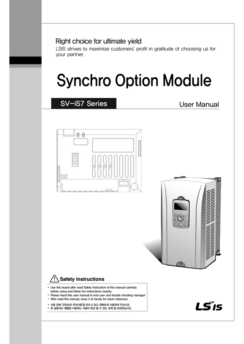
LSIS XGT Series User manual

Right choice for ultimate yield
LSIS strives to maximize customers' profit in gratitude of choosing us for your partner.
Programmable Logic Controller
Diagnostic Digital I/O Module
User’s Manual
Read this manual carefully before
installing,
wiring, operating, servicing
or inspecting this equipment.
Keep this manual within easy reach
for quick reference.
XGI-
D21D
XGQ-
RY1D
XGT Series
http://www.lsis.com

Safety Instruction
Before using the product …
For your safety and effective operation, please read the safety instructions thoroughly before using the product.
►Safety Instructions should always be observed in order to prevent accident or risk with the safe and
proper use the product.
►Instructions are divided into “Warning”and “Caution”, and the meaning of the terms is as follows.
This symbol indicates the possibility of serious injury or death if some applicable
instruction is violated
This symbol indicates the possibility of severe or slight injury, and property
damages if some applicable instruction is violated
Moreover, even classified events under its caution category may develop into serious accidents relying on
situations.Therefore we strongly advise users to observe all precautions properly just like warnings.
►The marks displayed on the product and in the user’s manual have the following meanings.
Be careful! Danger may be expected.
Be careful! Electric shock may occur.
►The user’s manual even after read shall be kept available and accessible to
any user of the product.
Warning
Caution

Safety Instruction
Safety Instructions for design process
Please install a protection circuit on the exterior of PLC so that the whole system may
operate safely regardless of failures from external power or PLC. Any abnormal output or
operation from PLC may cause serious problems to safety in whole system.
- Install protection units on the exterior of PLC like an interlock circuit that deals with opposite
operations such as emergency stop, protection circuit, and forward/reverse rotation or install an
interlock circuit that deals with high/low limit under its position controls.
- If any system error (watch-dog timer error, module installation error, etc.) is detected during
CPU operation in PLC, all output signals are designed to be turned off and stopped for safety.
However, there are cases when output signals remain active due to device failures in Relay and
TR which can’t be detected. Thus, you are recommended to install an addition circuit to monitor
the output status for those critical outputs which may cause significant problems.
Never overload more than rated current of output module nor allow to have a short circuit.
Over current for a long period time may cause a fire .
Never let the external power of the output circuit to be on earlier than PLC power, which may
cause accidents from abnormal output or operation.
Please install interlock circuits in the sequence program for safe operations in the system
when exchange data with PLC or modify operation modes using a
computer or other
external equipments
Read specific instructions thoroughly when conducting control operations
with PLC.
Warning

Safety Instruction
Safety Instructions for design process
Safety Instructions on installation process
I/O signal or communication line shall be wired at least 100mm away from a high-voltage
cable or power line.Fail to follow this
Caution
Use PLC only in the environment specified in PLC manual or general standard of data
sheet. If not, electric shock, fire, abnormal operation of the product may be caused.
Before install or remove the module, be sure PLC power is off. If not, electric shock or damage
on the product may be caused.
Be sure that every module is securely attached after adding a module or an extension
connector.If the product is installed loosely or incorrectly, abnormal operation, error or dropping
may be caused. In add
ition, contact failures under poor cable installation will be causing
malfunctions as well.
Be sure that screws get tighten securely under vibrating environments. Fail to do so will put
the product under direct vibrations which will cause electric shock, fire and abnormal operation.
Do not come in contact with conducting parts in each module, which may cause electric
shock, malfunctions or abnormal operation.
Caution

Safety Instruction
Safety Instructions for wiring process
Prior to wiring works, make sure that every power is turned off. If not, electric shock or
damage on the product may be caused.
After wiring process is done, make sure that terminal covers are installed properlybefore
its use.Fail to install the cover may cause electric shocks.
Warning
Check rated voltages and terminal arrangements in each product prior to its wiring
process.Applying incorrect voltages other than rated voltages and misarrangement among
terminals may cause fire or malfunctions.
Secure terminal screws tightly applying with specified torque.If the screws get loose, short
circuit, fire or abnormal operation may be caused.
Securing screws too tightly will cause
damages to the module or malfunctions, short circuit, and dropping.
Be sure to earth to the ground using Class 3 wires for FG terminals which is exclusively
used for PLC. If the terminals not grounded correctly, abnormal operation or electric shock
may be caused.
Don’t let any foreign materials such as wiring waste inside the module while wiring,
which may causefire, damage on the product or abnormal operation.
Make sure that pressed terminals get tighten following the specified torque. External
connector type shall be pressed or soldered using proper equipments.
Caution

Safety Instruction
Safety Instructions for test-operation and maintenance
Don’t touch the terminal when powered. Electric shock or abnormal operation may occur.
Prior to cleaning or tightening the terminal screws, let all the external power off including
PLC power. If not,electric shock or abnormal operation may occur.
Don’t let the battery recharged, disassembled, heated, short or soldered. Heat, explosion
or ignition may cause injuries or fire.
Warning
Do not make modifications or disassemble each module.Fire, electric shock or abnormal
operation may occur.
Prior to installing or disassembling the module, let all the external power off including
PLC power. If not,electric shock or abnormal operation may occur.
Keep any wireless equipment such as walkie-talkie or cell phones at least 30cm away
from PLC. If not, abnormal operation maybe caused.
When making a modification on programs or using run to modify functions under PLC
operations, read and comprehend all contents in the manual fully. Mismanagement will
cause damages to products and accidents.
Avoid any physical impact to the battery and prevent it from dropping as well. Damages
to battery may cause leakage from its fluid. When battery was dropped or exposed under strong
impact, never reuse the bat
tery again. Moreover skilled workers are needed when exchanging
batteries.
Caution

Safety Instruction
Safety Instructions for waste disposal
Product or battery waste shall be processed as industrial waste. The waste may discharge
toxic materials or explode itself.
Caution

Revision History
Revision History
Version Date Remark Page
V 1.0 ’14. 5 First Edition -
※The number of User’s manual is indicated right part of the back cover.
ⓒ2014 LSIS Co., Ltd All Rights Reserved.

About User’s Manual
1
Thank you for purchasing PLC of LSIS Co.,Ltd.
Before use, make sure to carefully read and understand the User’s Manual about the functions, performances, installation and
programming of the product you purchased in order for correct use and importantly, let the end user and maintenance
administrator to be provided with the User’s Manual.
The User’s Manual describes the product. If necessary, you may refer to the following description and order accordingly. In
addition, you may connect our website (http://www.lsis.com/) and download the information as a PDF file.
Relevant User’s Manuals
Title Description
XG5000 User’s Manual
(for XGK, XGB)
XG5000 software user manual describing online function such as
programming, print, monitoring, debugging by using XGK, XGB
CPU
XG5000 User’s Manual
(for XGI, XGR)
XG5000 software user manual describing online function such
as programming, print, monitoring, debugging by using XGI,
XGRCPU
XGK/XGB Instructions & Programming
User’s Manual
User’s manual for programming
to explain how to use
instructions that are used PLC system with XGK, XGB CPU.
XGI/XGR/XEC Instructions & Programming
User’s Manual User’s manual for programming
to explain how to use
instructions that are used PLC system with XGI, XGR,XEC CPU.
XGK CPU User’s Manual
(XGK-CPUA/CPUE/CPUH/CPUS/CPUU)
XGK-CPUA/CPUE/CPUH/CPUS/CPUU user manual describing
about XGK CPU module, power module, base, IO module,
specification of extension cable and system configuration, EMC
standard
XGI CPU User’s Manual
(XGI-CPUU/CPUH/CPUS)
XGI-CPUU/CPUH/CPUS
user manual describing about XGI
CPU module, power module, base, IO module, specification of
extension cable and system configuration, EMC standard
XGR redundant series User’s
Manual
XGR-CPUH/F, CPUH/T user manual describing about XGR
CPU module, power module, extension drive, base, IO module,
specification of extension cable and system configuration, EMC
standard
Current XGI-D21D, XGQ-RY1D manual is written based on the following version.
Related OS version list
Product name OS version
XGK-CPUH, CPUS, CPUA, CPUE, CPUU V4.2
XGI-CPUU/D, CPUU, CPUH, CPUS, CPUE V3.80
XGR-CPUH/F, CPUH/T V2.50
XG5000(XG-PD) V3.70

1
Ch1. Introduction………………………………………………………………………………………… 1-1 ~ 1-5
1.1 Features of Diagnostic Digital Input / Output Module....................................................................................................................1-1
1.1.1 Diagnostic Digital Input Module.....................................................................................................................................................1-1
1.1.2 Diagnostic Digital Output Module..................................................................................................................................................1-2
1.2 Cautions for Selecting Module.......................................................................................................................................................1-3
Chapter 2 Specifications and Functions……………………………………………………………… 2-1 ~ 2-15
2.1 General Specifications.................................................................................................................................................................... 2-1
2.2 Performance Specifications ...........................................................................................................................................................2-2
2.2.1 Performance specifications of diagnostic digital Input module (XGI-D21D)................................................................................2-2
2.2.2 Performance specifications of diagnostic digital Output module (XGQ-RY1D)..........................................................................2-3
2.3 Names and Functions of Parts.............................................................................................................................................................2-4
2.3.1 Names and Functions of parts of diagnostic digital Input module (XGI-D21D)...........................................................................2-4
2.3.2 Names and Functions of parts of diagnostic digital Output module (XGQ-RY1D).....................................................................2-5
2.4Functions of diagnostic digital I/O module...........................................................................................................................................2-6
2.4.1 Functions of diagnostic digital input module.................................................................................................................................2-6
2.4.2 Functions of diagnostic digital input module ............................................................................................................................ 2-10
3.1 Installation........................................................................................................................................................................................3-1
3.1.1 Installation environment.................................................................................................................................................................3-1
3.1.2 Cautions for handling.....................................................................................................................................................................3-2
3.2 Attachment/Detachment of modules.............................................................................................................................................3-5
3.2.1 Attachment/Detachment of modules............................................................................................................................................3-5
3.3 Wiring .......................................................................................................................................................................................... 3-9
3.3.1 I/O Device wiring.......................................................................................................................................................................... 3-9
3.3.2Specifications of wiring cable …………………………………………………………………………………………………. 3-9
3.3.3 Wiring for Diagnostic Digital Input module (XGI-D21D) …………………………………………………………………. 3-10
3.3.4 Wiring for Diagnostic Digital Output module (XGQ-RY1D) ………………………………………………………………. 3-11
◎Table of Contents ◎
Chapter 3 Installation and Wiring……………………………………………………………………… 3-1 ~ 3-9

2
4.1 Basic Troubleshooting Procedure .................................................................................................................................................4-1
4.2 Troubleshooting..............................................................................................................................................................................4-2
4.3 Cases..............................................................................................................................................................................................4-4
4.3.1 Trouble types and measures of input circuit.................................................................................................................................4-4
4.3.2 Trouble types and measures of output circuit ………………………………………………………………………………… 4-5
Appendix 1 Dimensions …………………………………………………………………………………… A1-1
Chapter 4 Troubleshooting……………………………………………………………………………… 4-1 ~ 4-5

Chapter 1 Introduction
1-1
Chapter 1 Introduction
1.1 Features of Diagnostic Digital Input / Output Module
This user manual describes Diagnostic Digital Input / Output Module of XGK/I/R PLC
1.1.1 Diagnostic Digital Input Module
Diagnostic Digital Input module receives and processes DC 24V input signal. It has a wire break detection function of each input
signal.
Input signal and wire break detection signal are displayed on the device of the CPU module, it canbe used in the PLC program.
Input
PLC CPU I/F
I/O
Conn.
Broken
Wire
diagnosis
Display
LED
R
DC24V
XGI-D21D
XGT CPU
XG5000
ProgramXG5000 I/F
Diagnosis
resistor
[Figure 1.1] Diagnostic digital input module system configuration
In order to operate wire break detection function normally, you must connect the diagnostic resistor in parallel with the input device
installed in the wiring, as shown in Figure 1.1.

Chapter 1 Introduction
1-2
1.1.2Diagnostic Digital Output Module
Diagnostic digital output module outputs output signal via the relay to the outside. It has a diagnostic function of the
internal signal and wire break detection for each output signal.
Diagnositic signals are displayed on the device of the CPU module, it can be used in the PLC program.
XG5000
XGT CPU
XG5000 I/F Program
PLC CPU I/F
Display LED
Relay
Drive
Circuit
SHUNT
Broken Wire
Detection Circuit
LOAD Out
COM
+ -
XGQ-RY1D
Internal Signal
Diagnosis Circuit
[Figure 1.2] Diagnostic digital output module system configuration
Digital output module provides diagnostic functionsof the following two.
1) Interal output signal diagnosis : Diagnosing whether internal output signal circuit is operating property.
2) Wire break detection : Diagnosing whether the disconnection of the external wiring connected to the relay.

Chapter 1 Introduction
1-3
1.2 Cautions for Selecting Module
It describes the cautions when selecting digital I/O modules.
1) There are two digital input types; current sink input and current source input
Since the wiring method of external input power varies in a DC input module, it should be selected considering the
specifications of input connectors.
2) The max. simultaneous input point varies depending on a module type. That is, it may be different, depending on input
voltage and ambient temperature. Please review the specifications of input module to apply before use.
3) In case of an application for highly frequent switching or inductive load switching, the relay output module may have a
shorter life, so it needs a transistor module or triac output module, instead of it.
4) If an output module operates an inductive load(L), the max. On/Off frequency should be limited to On per 1 second and
Off per 1 second, each.
5) In case a counter timer using DC/DC converter is used as a load in an output module, setting the average current may
cause a trouble because it may have inrush current in case of On or a certain cycle during operation. Therefore, if using the
foresaid load, it is necessary to connect resistance or inductor parallel to load or alternatively use a module of which max.
load current is large.
Output
module
R
Load
Output
module
Inductor
Load

Chapter 1 Introduction
1-4
6) The following figure shows the relay life of relay output module.
It also shows the max. life of relay used forrelayoutput.
No. of switching(×10 thousands)
100
50
30
20
10
100
105
321
0.5
Current(A)
DC 30V resistance load
AC 125V resistance load
AC 250V resistance load

Chapter 1 Introduction
1-5
7)Aclamped terminal with sleeve can not be used for the terminal strip. The clamped terminals suitable for terminal strip
are as follows(JOR 1.25-3:Daedong Electricity).
8) The cable size connected to a terminal strip should be 0.3~0.75 ㎟stranded cable and 2.8 ㎜thick. The cable may have
different current allowance depending on the insulation thickness.
9) The coupling torque available for fixation screw and terminal strip screw should follow the table below.
Coupling position
Coupling torque range
IO module terminal strip screw(M3 screw)
42 ~ 58 N·
㎝
IO module terminal strip fixation screw(M3 screw)
66 ~ 89 N·
㎝
6.0mm less than
6.0mm less than

Chapter 2 Specifications and Functions
2-1
Chapter 2 Specifications and Functions
2.1 General Specifications
General specifications of XGT series are as shown in Table 2.1.
No. Items Specification Reference
1
AmbientTemp.
0~55
°
C
2 StorageTemp. −25 ~ +70 °C
3
Ambienthumidity
5~95%RH(Non-condensing)
4
Storagehumidity
5~95%RH(Non-condensing)
5 Vibration
Occasional vibration
-
Frequency
Acceleration
Pulse width
Times
IEC61131-2
(IEC60068-2-6)
5
≤
f
<
8.4Hz
−
3.5 mm
10 times
each
direction
(X,YandZ)
8.4
≤
f
≤
150Hz
9.8m/s2(1G)
−
Continuous vibration
Frequency
Acceleration
Pulse width
5
≤
f
<
8.4Hz
−
1.75mm
8.4
≤
f
≤
150Hz
4.9m/s2(0.5G)
−
6 Shocks
•Peak acceleration :147m/s2(15G)
•Duration:11ms
•
Pulse wave type :Half-sine(3timeseachdirection pereachaxis)
IEC61131-2
(IEC60068-2-27)
7 Impulsenoise
Squarewave
impulsenoise
AC: ±1.500V,1 ㎲
DC:
±
900V
LSIS internaltest
spec.
Electrostatic
discharge
Voltage:4kV(Contactdischarge) IEC61131-2
IEC61000-4-2
Radiated
electromagnetic field
noise
80 ~1000 MHz, 10V/m IEC61131-2,
IEC61000-4-3
Fast transient
/Burst noise
Classificat
ion
Power
supply
Digital/Analog Input/Output,
Communication Interface
IEC61131-2
IEC61000-4-4
Voltage
2kV
1kV
8
Operationmbience
Free fromcorrosivegases andexcessivedust
9 Altitude Less than 2,000m
10 Pollutiondegree Lessthan2
11 Coolingmethod Air-cooling
[Table 2.1] General Specifications
1) IEC (International Electromechanical Commission)
: An international civil community that promotes international cooperation for standardization of electric/ electro
technology, publishes international standard and operates suitability assessment system related to the above.
2) Pollution Degree
: An index to indicate the pollution degree of used environment that determines the insulation performance of the
device. For example, pollution degree 2 means the state to occur the pollution of non-electric conductivity
generally, but the state to occur temporary electric conduction according to the formation of dew.
Notes

Chapter 2 Specifications and Functions
2-2
2.2 Performance Specifications
2.2.1 Performance specifications of diagnostic digital Input module (XGI-D21D)
Table 2.2 shows performance specifications of XGI-D21D.
Item Specifications
Input point 8points
Insulation method Photo coupler insulation
Rated input voltage / current DC24V / Approx. 8mA
Voltage range DC20.4~28.8V (5% and lower ripple rate)
On voltage / On current 19V and higher / 5.2mA and higher
Off voltage / On current 11V and lower / 4.7mA and lower
Response time
(Input filter)
Off -> On 1ms/3ms/5ms/10ms/20ms/70ms/100ms,Initial value:3ms
On -> Off 1ms/3ms/5ms/10ms/20ms/70ms/100ms,Initial value:3ms
Insulation withstand voltage DC 500V
Insulation resistance 10㏁and higher by Insulation ohmmeter
Diagnosis function Wire break detection
Common method 8point / 1COM
Suitable cable size Stranded cable between 0.3~0.75 ㎟(2.8mm and smaller outer dia.)
Suitable clamped terminal R1.25-3 (Sleeve built-in clamped terminal is not available)
Current consumption(㎃) 60mA
Operation display LED On with input On
LED On during wire break
External connection method 9 point Terminal strip connector (M3 X 6 screws)
Weight 95g
[Table 2.2] performance specifications of XGI-D21D

Chapter 2 Specifications and Functions
2-3
2.2.2 Performance specifications of diagnostic digital Output module (XGQ-RY1D)
Table 2.3shows performance specifications of XGQ-RY1D.
Item Specifications
Output point 8 points
Insulation method Relay insulation
Photo coupler insulation
Rated load voltage DC24V (resistance load) /AC220V (COSΨ= 1)
Rated load
current
1point 2A
Common 5A
Min. load voltage / current DC5V / 1mA
Max. load voltage / current AC250V, DC125V / 2A
Leakage current at Off 0.1mA (AC220V, 60Hz)
Max. switching frequency 1,800 times/hour
Surge killer None
Life
Mechanical 20 million and more times
Electrical
Rated load voltage/current 100 thousand and more times
AC200V / 1.5A, AC240V / 1A (COSΨ= 0.7) 100 thousand and more times
AC200V / 1A, AC240V / 0.5A(COSΨ= 0.35) 100 thousand and more times
DC24V / 1A, DC100V / 0.1A(L/ R = 7ms) 100 thousand and more times
Response
time
Off -> On 10ms and lower
On -> Off 12ms and lower
Diagnosis function Wire break detection
Internal output signal diagnosis
Common method 8 point/1COM
Current consumption(mA) Max. 400mA
Operation display LED On with output On
LED On during wire break
LED On when the internal output signal fail
External connection method 9 point Terminal strip connector (M3 X 6 screws)
Weight 145g
[Table 2.3] performance specifications of XGQ-RY1D

Chapter 2 Specifications and Functions
2-4
2.3 Names and Functions of Parts
2.3.1 Names and Functions of parts of diagnostic digital Input module (XGI-D21D)
XGI-D21D
1
2
3
4
5
6
7
8
9
01
02
03
00
04
05
06
07
COM
+-
24 Vd.c
8mA
입력포트 표시
제품 형명
R
R
0 1 2 3 4 5 6 7
8 9 A B C D E F
IN
DIAG
①
②
No.
Name
Description
①LED Display
1. IN : Input status (0 ~7)
▶On : Input On
▶Off : Input Off
2. DIAG : Diagnosis status (8 ~F)
▶On : broken wire occurs
▶Off : Normal state
②Input wiring connector Connector for input wiring
Note
Refer to Chapter 2.4 Functions of diagnostic digital I/O module in this manual for Internal MemoryConfiguration and LED
Display.
Refer to Chapter 3.3 Wiring in thismanual forWiring of diagnostic digital Inputmodule.
Other manuals for XGT Series
21
This manual suits for next models
2
Table of contents
Other LSIS Control Unit manuals

LSIS
LSIS XGT Series User manual

LSIS
LSIS SV-iS7 series User manual

LSIS
LSIS Starvert iG5A Series User manual

LSIS
LSIS XGT Series User manual

LSIS
LSIS CENT-S100 User manual

LSIS
LSIS XGT Series User manual
LSIS
LSIS XBL-EIPT User manual

LSIS
LSIS XGT Series User manual
LSIS
LSIS XGT Series User manual

LSIS
LSIS S100 Series User manual
Popular Control Unit manuals by other brands

Emerson
Emerson CL600 instruction manual

Energeeks
Energeeks EG-MODPERS001 Quick installation guide

Edwards
Edwards CTM Installation sheet

Cooper Crouse-Hinds
Cooper Crouse-Hinds eLLK 92 NIB Series Supplementary instructions

Innodisk
Innodisk EMP2 SERIES user manual

urmet domus
urmet domus ALPHA 1168/50 installation manual