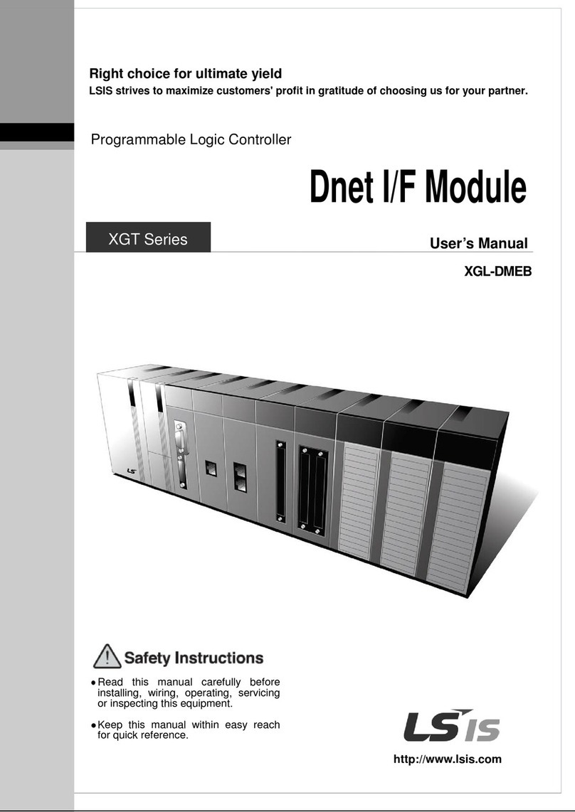
LSIS XGT Series User manual

Right choice for ultimate yield
LSIS strives to maximize customers' profit in gratitude of choosing us for your partner.
Programmable Logic Controller
Pnet I/F Module
User’s Manual
Read this manual carefully before
installing,
wiring, operating, servicing
or inspecting this equipment.
Keep this manual within easy reach
for quick reference.
XGL-
PMEA
XGL-PME
B
XGL-PMEC
XGT Series
http://www.lsis.com

Safety Instructions
Before using the product …
For your safety and effective operation, please read the safety instructions
thoroughly before using the product. Safety Instructions should always be
observed in order to prevent accident or risk with the safe and proper use the
product.
Instructions are divided into “Warning” and “Caution”, and the meaning of the
terms is as follows.
This symbol indicates the possibility of serious injury
or death if some applicable instruction is violated
This symbol indicates the possibility of severe or
slight injury, and property damages if some
applicable instruction is violated
Moreover, even classified events under its caution category may develop
into serious accidents relying on situations. Therefore we strongly advise users
to observe all precautions properly just like warnings.
The marks displayed on the product and in the user’s manual have the
following meanings.
Be careful! Danger may be expected.
Be careful! Electric shock may occur.
The user’s manual even after read shall be kept available and accessible to
any user of the product.
Warning
Caution

Safety Instructions
Safety Instructions for design process
1. Please install a protection circuit on the exterior of PLC so that the
whole system may operate safely regardless of failures from
external power or PLC. Any abnormal output or operation from PLC
may cause serious problems to safety in whole system.
(1) Install protection units on the exterior of PLC like an interlock circuit
that deals with opposite operations such as
emergency stop,
protection circuit, and forward/reverse rotation or install an interlock
circuit that deals with high/low limit under its position controls.
(2) If any system error (watch-dog timer error, module installation error,
etc.) is detected during CPU operation in PLC, all output signals are
designed to be turned off and stopped for safety. However, there
are cases when output signals remain active due to device failures
in Relay and TR which can’t be detected
. Thus, you are
recommended to install an addition circuit to monitor
the output
status for those critical outputs which may cause significant
problems.
2. Never overload more than rated current of output module nor
allow to have a short circuit. Over current for a long period time may
cause a fire .
3. Never let the external power of the output circuit to be on earlier
than PLC power, which may cause accidents from abnormal output or
operation.
4. Please install interlock cir
cuits in the sequence program for safe
operations in the system when exchange data with PLC or modify
operation modes using a
computer or other external equipments
Read specific instructions thoroughly when conducting control
operations with PLC.
Warning

Safety Instructions
Safety Instructions for design process
Safety Instructions on installation process
I/O signal or communication line shall be wired at least 100mm
away from a high-voltage cable or power line.Fail to follow this
instruction may cause malfunctions from noise
Caution
1. Use PLC only in the environment specified in PLC manual or
general standard of data sheet.
If not, electric shock, fire,
abnormal operation of the product may be caused.
2. Before install or remove the module, be sure PLC power is off.
If not, electric shock or damage on the product may be caused.
3. Be sure that every module is securely attached after adding a
module or an extension connector.
If the product is installed
loosely or incorrectly, abnormal operation, error or dropping may
be caused.
In addition, contact failures under poor cable
installation will be causing malfunctions as well.
4. Be sure that screws get tighten securely under vibrating
environments.
Fail to do so will put the product under direct
vibrations which will cause electric shock, fire and abnormal
operation.
5. Do not come in contact with conducting parts in each module,
which may cause electric shock, malfunctions
or abnormal
operation.
Caution

Safety Instructions
Safety Instructions for wiring process
1. Prior to wiring works, make sure that every power is turned off.
If not, electric shock or damage on the product may be caused.
2. After wiring process is done
, make sure that terminal covers
are installed properly before its use.Fail to install the cover may
cause electric shocks.
Warning
1. Check rated voltages
and terminal arrangements in each
product prior to its wiring process.Applying incorrect voltages
other than rated voltages and misarrange
ment among terminals
may cause fire or malfunctions.
2. Secure terminal screws tightly applying with specified torque.If
the screws get loose, short circuit, fire or abnormal operation may be
caused. Securi
ng screws too tightly will cause damages to the
module or malfunctions, short circuit, and dropping.
3. Be sure to earth to the ground using Class 3 wires for FG
terminals which is exclusively used for PLC. If the terminals not
grounded correctly, abnormal operation or electric shock may be
caused.
4. Don’t let any foreign materials such as wiring waste inside the
module while wiring,
which may cause fire, damage on the
product or abnormal operation.
5. Make sure that pressed terminals
get tighten following the
specified torque. External connector type shall be pressed or
soldered using proper equipments.
Caution

Safety Instructions
Safety Instructions for test-operation and
maintenance
1. Don’t touch the terminal when powered
. Electric shock or
abnormal operation may occur.
2. Prior to cleaning or tightening the terminal screws, let all the
external power off including PLC power. If not, electric shock or
abnormal operation may occur.
3. Don’t let the battery recharged, disassembled, heated, short or
soldered. Heat, explosion or ignition may cause injuries or fire.
Warning
1. Do not make modifications or disassemble each module.Fire,
electric shock or abnormal operation may occur.
2. Prior to installing or disassemb
ling the module, let all the
external power off including PLC power. If not, electric shock or
abnormal operation may occur.
3. Keep any wireless equipment such as walkie-talkie or cell
phones at least 30cm away from PLC. If not, abnormal operation
may be caused.
4. When making a modification
on programs or using run to
modify functions under PLC operations, read and comprehend
all contents in the manual fully. Mism
anagement will cause
damages to products and accidents.
5.
Avoid any physical impact to the battery and prevent it from
dropping as well. Damages to battery may cause leakage from its
fluid. When battery was dropped or exposed under strong impact,
never reuse the battery again. Moreover skilled workers are needed
when exchanging batteries.
Caution

Safety Instructions
Safety Instructions for waste disposal
Product or battery waste shall be processed as industrial waste.
The waste may discharge toxic materials or explode itself.
Caution

Revision History
※The number of User’s manual is indicated right part of the back cover.
ⓒLSIS Co., Ltd 2006All Rights Reserved.
Version Date Remark Page
V 1.0 ’06.02 First Edition -
V1.1 ’07.10 XGI-CPUU added -
V 2.0 ’10.08 XGR CPU added -
Ch. 11 Compliance with EMC Specification added -
XGL-PMEC added -
PROFICON configuration tool added -
Automatic Network Scan modified Ch.9.1.1
XGL-PSRA added Ch.1.3.3
V 2.1 ’11.05 How to enable link through flag added Ch.5.2.3
V 2.2 ’11.06 Performance specifications added
- Max. number of modules per node : 24 Modules Ch.2.2
V2.3 ’14.11 XG5000 V4.0 UI Updated -
V2.4 ’16.03
Add XGL-PMEB
- PROFIBUS DPv1 setting
- P2P communication setting
- XG5000 UI updated (XGL-PMEB contents, P2P settings)
-

About User’s Manual
1
Congratulations on purchasing PLC of LSIS Co.,Ltd.
Before use, make sure to carefully read and understand the User’s Manual about the functions, performances, installation and
programming of the product you purchased in order for correct use and importantly, let the end user and maintenance
administrator to be provided with the User’s Manual.
The User’s Manual describes the product. If necessary, you may refer to the following description and order accordingly. In
addition, you may connect our website (http://www.lsis.com/) and download the information as a PDF file.
Relevant User’s Manuals
Title Description
XG5000 User’s Manual XG5000 software user manual describing online function such as
programming, print, monitoring, debugging by using XGK, XGB
CPU
XG5000 User’s Manual
(for XGI, XGR)
XG5000 software user manual describing online function such
as programming, print, monitoring, debugging by using XGI,
XGRCPU
XGK/XGB Instructions & Programming
User’s Manual
User’s manual for programming
to explain how to use
instructions that are used PLC system with XGK, XGB CPU.
XGI/XGR Instructions & Programming
User’s Manual User’s manual for programming
to explain how to use
instructions that are used PLC system with XGI, XGR CPU.
XGK CPU User’s Manual
(XGK-CPUA/CPUE/CPUH/CPUS/CPUU)
XGK-CPUA/CPUE/CPUH/CPUS/CPUU user manual describing
about XGK CPU module, power module, base, IO module,
specification of extension cable and system configuration, EMC
standard
XGI CPU User’s Manual
(XGI-CPUU)
XGI-CPUU user manual describing about XGK CPU module,
power module, base, IO module, specification of extension cable
and system configuration, EMC standard
XGR redundant series User’s
Manual
XGR-CPUU user manual describing about XGR CPU module,
power module, extension drive, base, IO module, specification of
extension cable and system configuration, EMC standard
N Configurator User’s Manual
User’s manual for Pnet, Dnet configuration tool, N Configurator
Current user manual is written based on the following version.
Related OS version list
Model O/S version
XGK-CPUH, CPUS, CPUA, CPUE V2.0
XGI-CPUU, CPUH V2.0
XG5000 V4.2
XGR-CPUH/F, CPUH/T V1.0

◎
Table of Contents
◎
Chapter 1 Introduction
1.1 Introduction -------------------------------------------------------------------------------------------------------- 1-1
1.2 Characteristics ---------------------------------------------------------------------------------------------------- 1-1
1.3 Product Configuration ------------------------------------------------------------------------------------------- 1-2
1.3.1 Model Name------------------------------------------------------------------------------------------------ 1-2
1.3.2 Available number by CPU------------------------------------------------------------------------------- 1-2
1.3.3 Slave Device ----------------------------------------------------------------------------------------------- 1-3
1.4 Software ------------------------------------------------------------------------------------------------------------- 1-4
1.4.1 Check list for the software ------------------------------------------------------------------------------ 1-4
1.4.2 XG5000------------------------------------------------------------------------------------------------------ 1-5
1.4.3 Checking the version------------------------------------------------------------------------------------- 1-5
Chapter 2 Specifications
2.1 General Specifications ------------------------------------------------------------------------------------------ 2-1
2.2 Performance Specifications ----------------------------------------------------------------------------------- 2-2
2.3 Structure & Characteristics ------------------------------------------------------------------------------------ 2-3
2.3.1 Structure of Pnet I/F module -------------------------------------------------------------------------- 2-3
2.4 Cable Specifications --------------------------------------------------------------------------------------------- 2-6
2.4.1 Cable specifications of Belden network ------------------------------------------------------------- 2-6
Chapter 3 Installation and Test Operation
3.1 Precautions for Installation ------------------------------------------------------------------------------------ 3-1
3.1.1 Precautions for Installation --------------------------------------------------------------------------- 3-1
3.2 From Setting to Operation ------------------------------------------------------------------------------------- 3-2
3.3 Installation of the product -------------------------------------------------------------------------------------- 3-3
3.3.1 Installation of XGL-PMEA ---------------------------------------------------------------------------- 3-3
3.4 Test Operation ---------------------------------------------------------------------------------------------------- 3-6
3.4.1 Precautions for system configuration ------------------------------------------------------------- 3-6

Chapter 4 System Configuration
4.1 System Configuration of Network ---------------------------------------------------------------------------- 4-1
4.1.1 XGT Pnet + Smart I/O -------------------------------------------------------------------------------- 4-1
4.1.2 XGT Pnet + Composite System -------------------------------------------------------------------- 4-2
Chapter 5 Communication Program
5.1 Communication Program --------------------------------------------------------------------------------------- 5-1
5.1.1 Type of communication program ------------------------------------------------------------------- 5-1
5.2 XG5000 ------------------------------------------------------------------------------------------------------------- 5-2
5.2.1 Setting PLC type----------------------------------------------------------------------------------------- 5-2
5.2.2 Registration of the communication module ------------------------------------------------------- 5-4
5.2.3 Uploading High Speed Link parameter and setup----------------------------------------------- 5-8
5.2.4 Setting P2P parameter---------------------------------------------------------------------------------5-11
Chapter 6 SyCon Setting
6.1 Introduction -------------------------------------------------------------------------------------------------------- 6-1
6.1.1 Main functions ------------------------------------------------------------------------------------------ 6-1
6.1.2 Characteristics ------------------------------------------------------------------------------------------ 6-1
6.2 Installation --------------------------------------------------------------------------------------------------------- 6-1
6.2.1 System requirements --------------------------------------------------------------------------------- 6-1
6.2.2 Software installation ----------------------------------------------------------------------------------- 6-2
6.3 Communication settings in SyCon --------------------------------------------------------------------------- 6-8
6.3.1 Initial screen --------------------------------------------------------------------------------------------- 6-8
6.3.2 Composition of menu --------------------------------------------------------------------------------- 6-9
6.3.3 New file --------------------------------------------------------------------------------------------------6-11
6.3.4 Master selection ---------------------------------------------------------------------------------------6-12
6.3.5 Slave selection -----------------------------------------------------------------------------------------6-15
6.3.6 Bus parameter -----------------------------------------------------------------------------------------6-17
6.4 On-line Function -------------------------------------------------------------------------------------------------6-18
6.4.1 Introduction ---------------------------------------------------------------------------------------------6-18
6.4.2 Online to the CIF --------------------------------------------------------------------------------------6-18
6.4.3 Automatic network scan -----------------------------------------------------------------------------6-18
6.4.4 Start/Stop communication ---------------------------------------------------------------------------6-20
6.4.5 Debug mode --------------------------------------------------------------------------------------------6-20
6.4.6 Diagnostic functions ----------------------------------------------------------------------------------6-20

Chapter 7 N Configurator Setting
7.1 Introduction -------------------------------------------------------------------------------------------------------- 7-1
7.1.1 Main functions ------------------------------------------------------------------------------------------ 7-1
7.1.2 Characteristics ------------------------------------------------------------------------------------------ 7-1
7.2 Installation --------------------------------------------------------------------------------------------------------- 7-2
7.2.1 System requirements --------------------------------------------------------------------------------- 7-2
7.2.2 How to install Program --------------------------------------------------------------------------------- 7-2
7.3 Start PROFICON -------------------------------------------------------------------------------------------------- 7-3
7.3.1 Screen composition------------------------------------------------------------------------------------- 7-3
7.3.2 Menu composition--------------------------------------------------------------------------------------- 7-4
7.3.3 New Project(New File) --------------------------------------------------------------------------------7-10
7.4 Network composition through PROFICON-----------------------------------------------------------------7-11
7.4.1 Master composition ------------------------------------------------------------------------------------7-11
7.4.2 Slave composition--------------------------------------------------------------------------------------7-13
7.4.3 Bus parameter-------------------------------------------------------------------------------------------7-16
7.5 Download and upload Network Configuration-------------------------------------------------------------7-17
7.5.1 Download Network Settings -------------------------------------------------------------------------7-17
7.5.2 Upload Network Settings -----------------------------------------------------------------------------7-19
7.6 Diagnosis function------------------------------------------------------------------------------------------------7-20
7.6.1 Start / Stop Communication--------------------------------------------------------------------------7-20
7.6.2 Debug mode (Start/Stop Debug Mode, Device Diagnostics) --------------------------------7-20
7.6.3 Live List ---------------------------------------------------------------------------------------------------7-22
7.6.4 Automatic Network Scan------------------------------------------------------------------------------7-23
7.6.5 I/O Data Monitoring ------------------------------------------------------------------------------------7-24
7.6.6 Disconnection Report----------------------------------------------------------------------------------7-25
7.6.7 Master information (Device Information)----------------------------------------------------------7-25
7.6.8 Master reset (Firmware Reset)----------------------------------------------------------------------7-25
Chapter 8 High-speed Link
8.1 Introduction -------------------------------------------------------------------------------------------------------- 8-1
8.2 Process of High-speed Link Send/Receive Data --------------------------------------------------------- 8-2
8.3 Operation Sequence of High-speed Link ------------------------------------------------------------------- 8-3
8.4 High Speed Link Parameter Setting--------------------------------------------------------------------------- 8-4
8.5 High-speed Link Information ---------------------------------------------------------------------------------8-10
8.5.1 Monitor of High-speed link information ----------------------------------------------------------8-12

Chapter 9 P2P
9.1 Introduction -------------------------------------------------------------------------------------------------------- 9-1
9.2 Process of P2P Read/Write Data ---------------------------------------------------------------------------- 9-2
9.3 Operation Sequence of P2P ---------------------------------------------------------------------------------- 9-3
9.4 P2P Parameter Setting------------------------------------------------------------------------------------------- 9-4
9.5 P2P Informatio-n ------------------------------------------------------------------------------------------------- 9-9
Chapter 10 Program Example
10.1 Example of Communication with PMEA -----------------------------------------------------------------10-1
10.1.1 SyCon settings ---------------------------------------------------------------------------------------10-1
10.1.2 XG5000 settings -------------------------------------------------------------------------------------10-9
10.2 Example of Communication with PMEA ---------------------------------------------------------------10-14
10.2.1 PROFICON settings ------------------------------------------------------------------------------10-14
10.2.2 XG5000 settings -----------------------------------------------------------------------------------10-23
Chapter 11 Troubleshooting
11.1 Symptoms and Management by LED Status -----------------------------------------------------------11-1
11.2 System Diagnosis of XG5000 ------------------------------------------------------------------------------11-2
11.2.1 Information on communication module ---------------------------------------------------------11-2
11.2.2 High-speed link ---------------------------------------------------------------------------------------11-3
11.2.3 Log ------------------------------------------------------------------------------------------------------11-3
11.2.4 Auto-scan ----------------------------------------------------------------------------------------------11-4
11.3 Diagnosis of Communication Module through XG5000 ----------------------------------------------11-5
11.4 Troubleshooting ------------------------------------------------------------------------------------------------11-6
11.4.1 SyCon abnormal connection ----------------------------------------------------------------------11-6
11.4.2 XG5000 abnormal connection --------------------------------------------------------------------11-7
11.4.3 Abnormal connection with slave module -------------------------------------------------------11-8
Chapter 12 Compliance with EMC Specifications
12.1 Requirements Complying with EMC Specifications ----------------------------------------------------12-1
12.1.1 EMC specifications -----------------------------------------------------------------------------------12-1
12.1.2 Panel-----------------------------------------------------------------------------------------------------12-2
12.1.3 Cable-----------------------------------------------------------------------------------------------------12-3
12.2 Requirements Complying with Low Voltage Direction ------------------------------------------------12-4
12.2.1 Specifications applicable to XGT series---------------------------------------------------------12-4
12.2.2 Selection of XGT series PLC-----------------------------------------------------------------------12-4

Appendix
A.1 Terminology -------------------------------------------------------------------------------------------------------A-1
A.2 List of Flags -------------------------------------------------------------------------------------------------------A-3
A.2.1 High-speed link flags ------------------------------------------------------------------------------------A-3
A.2.2 Link devices
(N) ------------------------------------------------------------------------------------------A-6
A.3 Dimensions --------------------------------------------------------------------------------------------------------A-8

Chapter 1 Introduction
1 - 1
Chapter 1 Introduction
1.1 Introduction
This user’s manual is to describe Profibus-DP (Decentralized Peripherals) Master I/F module (hereinafter
referred to as Pnet I/F module) among communication modules of XGT PLC system.
Profibus-DP is specified in IEC Fieldbus Standard IEC 1158.
In this communication, Token Ring is used to control the communication and to configure the network easily.
Pnet I/F module is a module to control the field bus with Twisted Shielded Pair Copper Cable applied.
1.2 Characteristics
XGT Pnet I/F module has the characteristics as follows;
▶Conforms to the international standard of EN 50170
▶Supports Auto Baud Rate Detect
▶Supports Sync/Freeze mode
▶Max. input data : 244 Bytes/Slave
▶Max. output data: 244 Bytes/Slave
▶Max. data size : 244 Bytes/Slave, 10 kbyte/Master
▶Communication speed : 9.6k, 19.2k, 31.25k, 45.45k, 93.7k, 187.5k, 500k, 1.5M, 3M, 6M, 12M
Active Stations, Master Devices
PC
Passive Stations (Slave Devices) are polled
PROFIBUS

Chapter 1 Introduction
1 - 2
1.3 Product Configuration
1.3.1 Model Name
This describes on the product configuration of the XGT Pnet I/F module.
Model
Contents
Remark
XGK/XGI/XGR
XGL-PMEA Profibus-DP Master Supports DP-V0
XGL-PMEC Profibus-DP Master
XGL-PMEB Profibus-DP Master Supports DP-V1
Note
(1) XGT Pnet supports only Profibus-DP. FMS, PA are not supported and protocol conversion is
available by the coupler
(2) Support of the DP version
1) DP-V0: Periodical data exchange between the PLC and the slave device
(Node diagnosis, module status, specific channel diagnosis)
2) DP-V1: Asynchronous data exchange between the PC or PLC and the slave device, integration of
EDD and FDT, fail-safe communication, alarm
3) DP-V2:
supports broadcast, clock synchronization and time stamp, HART, upload/download,
redundancy
1.3.2 Available number by CPU
You can mount up to 12 Pnet I/F module. If possible, mount the module in the basic base for best
performance of the communication module. The following table indicates the available service type by the
CPU. When configuring the system, apply this considering the number of the communication module.
Item
XGK XGI XGR
XGK-
CPUH
/CPUU
XGK-
CPUA
/CPUS
/CPUSN
XGK-
CPUHN
/CPUUN
XGK-
CPUE
XGI-
CPUUN XGI-
CPUU
XGI-
CPUH XGI-
CPUS XGI-
CPUE
XGR-
CPUH/T
XGR-
CPUH/F
The number of the
module using High
Speed Link (Max.)
12 12 12
The number of the
module using P2P
(Max.)
XGL-PMEA/C: Not supported
XGL-PMEB: 8
The number of
available
expansion base
(Max.)
7 3 7 1 7 3 1 31

Chapter 1 Introduction
1 - 3
1.3.3 Slave Device
The Pnet I/F module can be connected with Smart I/O series and available product list is as follows.
(1) Master module
Item
Connection
cable
Model Product code contents Remark
Master
module Twisted pair
(Electricity)
XGL-PMEA
47200001
Profibus DPv0
Sycon
XGL-PMEC
47200103
Profibus DPv0
N Configurator
XGL-PMEB
47200180
Profibus DPv1
(2) Slave module
Item
Connection cable
Model
Product code
contents
Remark
Slave
module
Twisted pair
(electricity)
G7L-PBEA 46270031
Connected at the K120S expansion
part
K120S/K80S/GM7/GM7
U
GPL-D22A
47060007
DC input 16 points
Fixed type, 9-pin
communication
connector
GPL-D24A
47060009
DC input 32 points
GPL-TR2A
47060008
TR output 16 (0.1A, Sink)
GPL-TR4A
47060010
TR output 32 (0.1A, Sink)
GPL-RY2A
47060011
Relay output 16
GPL-DT4A
47060012
DC input 16/ TR output 16
GPL-D22C
47060046
DC input 16
Removable type, 9-pin
communication
connector
GPL-D24C
47060047
DC input 32
GPL-TR2C
47060048
TR output 16 (0.5A, Source)
GPL-TR4C
47060049
TR output 32 (0.5A, Source)
GPL-RY2C
47060051
Relay output 16
GPL-DT4C
47060050
DC input16/ TR output 16
GPL-TR2B
47060059
TR output 16 (0.5A, Source)
Fixed type, 9-pin
communication
connector
GPL-TR4B
47060058
TR output 32 (0.5A, Source)
GPL-DT4B
47060060
DC input16/ TR output 16
GPL-TR2A1
47060084
TR output 16 (0.5A, Sink)
GPL-TR4A1
47060076
TR output 32(0.5A, Sink)
GPL-DT4A1
47060078
DC input 16/ TR output 16
GPL-TR2C1
47060085
TR output 16 (0.5A, Sink)
Removable type, 9-pin
communication
connector
GPL-TR4C1
47060077
TR output 32 (0.5A, Sink)
GPL-DT4C1
47060079
DC input 16/ TR output 16
GPL-AV8C
47060123
Analog voltage input, 8 channels
GPL-AC8C
47060124
Analog current input 8 channels
GPL-DV4C
47060125
Analog voltage output, 8
GPL-DC4C
47060126
Analog current output, 8
XPL-BSSA 47060130 Expansion type Pnet I/F module
Module for expansion
type Pnet I/F module
XGL-PSRA
47200128
Pnet Remote I/F module
Remote I/F module
[Table1.3.1] Pnet I/F module product list (Smart I/O)
Note
1) Fixed type: The product whose I/O terminal block is fixed at the module
2) Removable type: The product whose I/O terminal block can be removed

Chapter 1 Introduction
1 - 4
1.4 Software
This describes on the software tool for the Pnet I/F module. For programming and application, refer to the
followings
1.4.1 Check list for the software
(1) Software list
Item Programming tool
Communication
configuration tool
XGL-PMEA/
XGL-PMEC/
XGL-PMEB
Profibus-DP master module XG5000
(2) Selecting the CPU (Version) to use the Pnet I/F module
Item Model
Available version
(recommended)
Remark
XGK series
XGK-CPUH V2.0
XGK-CPUS
V2.0
XGK-CPUA
V2.0
XGK-CPUE
V2.0
XGK-CPUU
V1.0
XGI series
XGI-CPUH
V1.0
XGI-CPUU
V1.0
XGR series
XGR-CPUH/T
V1.0
XGR-XPUH/F
V1.0
Software
XG5000
V4.2
SyCon
V2.0
Configuration tool for XGL-PMEA
N Configurator
V3.1.0.2
Configuration tool for XGL-PMEB/C
Note
(1) You can download the above software from our web site. In case Internet is available, visit the
nearest distributor and get the installation CD.
Web site address: http://www.lsis.com/
(2) You can program the XG5000 through the RS-232C port and USB of the CPU module. For the
cable, refer to wiring diagram of the CPU module.
(3) You can configure the network system by SyCon through the “Config” port of the XGL-PMEA.
Only 9-pin serial port is available and simultaneous connection with XG5000 is not available.
(4) You can set the parameter by N Configurator for XGL-PMEB/C through the USB port of the CPU
module and connection with XG5000 is available.
(5) In case you use the product other than available version, some function may not work properly. If
possible, use the recommended version and check the compatibility.

Chapter 1 Introduction
1 - 5
1.4.2 XG5000
XG5000 is software tool dedicated for the communication module including Pnet I/F module. Setting
the basic parameter, writing the frame and network diagnosis are available for the communication
module. Fore more detail, refer to Ch5. XG5000.
The following figure is an initial screen of the XG5000
[Figure 1.4.1] XG5000 initial screen
1.4.3 Checking the version
Before using the Pnet I/F module, check the version of the module
(1) Check through the XG5000
This is method reading the communication module information through online connection
If it is under normal interface with the CPU, you can get the information as follows.
a) Execute the XG5000
b) Connect to the CPU through “Connect” on the “Online” menu.
c) After connection, execute [Online]-[Communication module setting]-[System Diagnosis]
d) In the “System Diagnosis” screen, select “Module Information” by double-clicking the
communication module and pop-up window
e) Software information appears at the right-bottom.

Chapter 1 Introduction
1 - 6
[Figure 1.4.2] Checking the version of the module through the XG5000
(2) Check through the case label of the product
The module information is attached at the external case every communication modules
In case online connection is not available, take a module apart and check the label in the module case.
Other manuals for XGT Series
21
This manual suits for next models
3
Table of contents
Other LSIS Control Unit manuals

LSIS
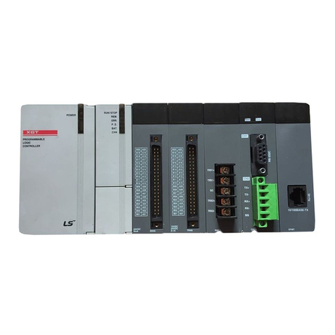
LSIS XGT Series User manual
LSIS
LSIS XGT Series User manual

LSIS
LSIS XGT Series User manual
LSIS
LSIS XGT Series User manual
LSIS
LSIS SV-iS7 series User manual

LSIS
LSIS CENT-S100 User manual
LSIS
LSIS XGT Series User manual

LSIS
LSIS XGT Series User manual

LSIS
LSIS XGT Series User manual

LSIS
LSIS XGB Series User manual
Popular Control Unit manuals by other brands

Centurion
Centurion G-SWITCH-22 installation guide

Ditel
Ditel Kosmos KOS1010 quick start guide

Wilo
Wilo Wilo-Control EC-Drain PD1 Installation and operating instructions

Behringer
Behringer DUAL ENVELOPE GENERATOR MODULE 1003 quick start guide

Pulsar
Pulsar PC2 AWZ 518 quick start guide

TANDBERG
TANDBERG MCU Technical description