LSL K12R Install guide

——————————————————— Zubehör von —Das Original ——
Rev. 00 18/04/2012 Seite 1 von 3
Anbauanleitung
Artikel-Nr.
:
121B029
Produkt
:
Superbike Lenkerkit
Modell
:
BMW K1200R2005 – 2008 / K1300R2009
Typ
:
K12R / K12S
Wichtige Hinweise:
Lesen Sie die Anleitung sorgfältig durch und beachten Sie alle Sicherheitshinweise. Führen Sie
diese Montage nur durch, wenn Sie dafür qualifiziert sind, andernfalls empfehlen wir dringend die
Montage in einer Fachwerkstatt. Ein fehlerhafter Anbau kann das Fahrverhalten des Motorrades
negativ beeinflussen und Ihre Gesundheit und Ihr Leben gefährden.
Im Folgenden werden die unten aufgeführten Symbole verwandt, beachten Sie bitte diese
Hinweise.
Warnung! Wichtiger Montage-Hinweis. Bei Nichtbeachtung können Gesundheit und
Leben gefährdet sein.
Tipp zur Montage, Pflege oder zur Vermeidung von Schäden.
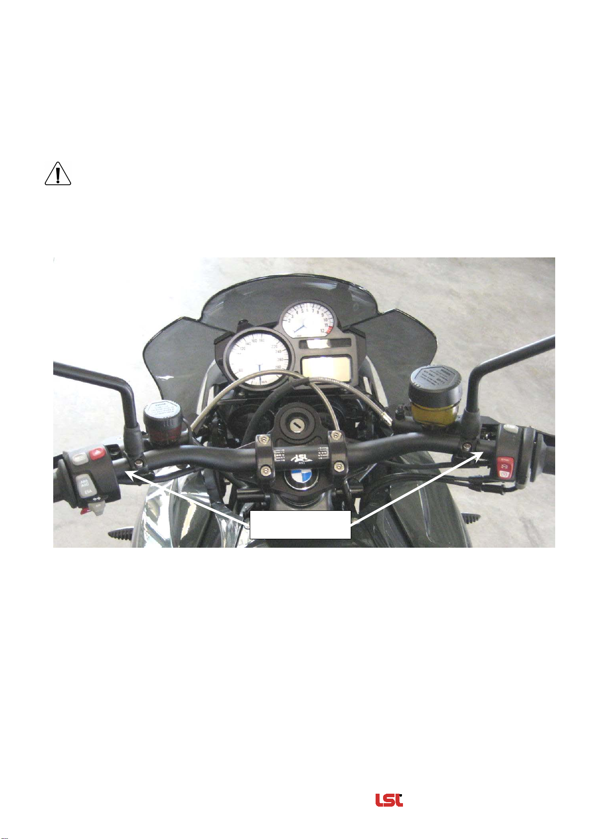
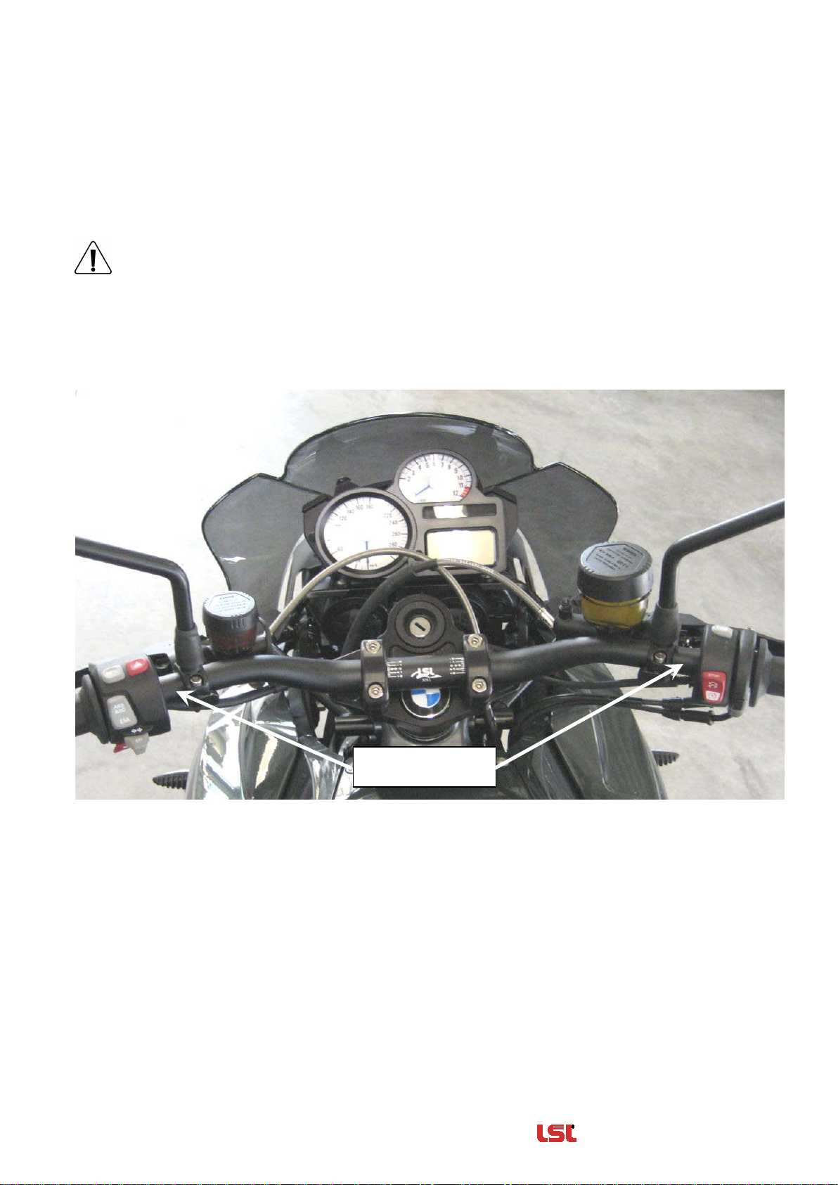
Montage:
Zur Sicherheit der elektrischen Systeme sollte während der Montage die Batterie am
Minuspol abgeklemmt werden.
Griffarmaturen, Bedienungsarmaturen und Hydraulikzylinder vom Lenker demontieren.
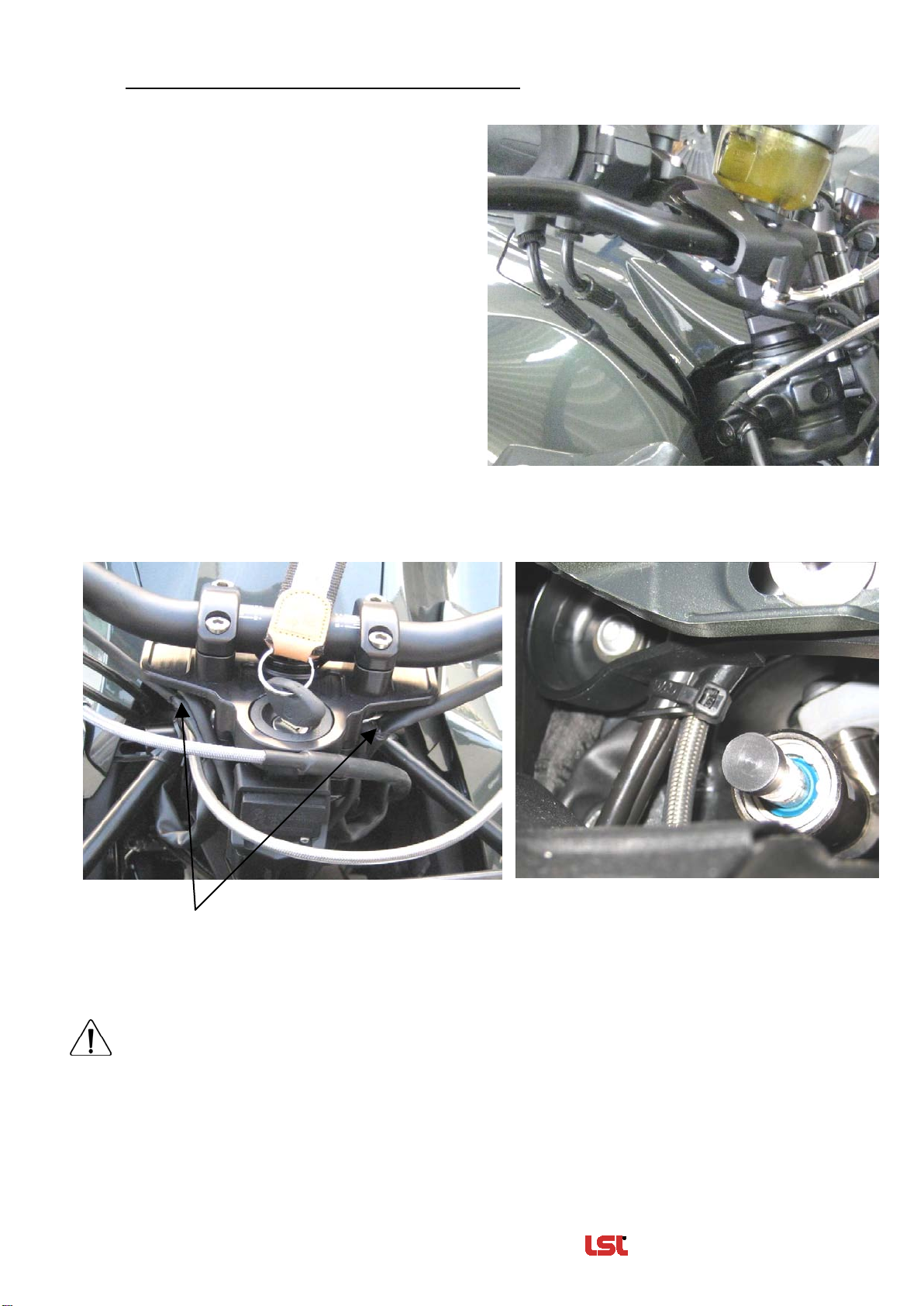
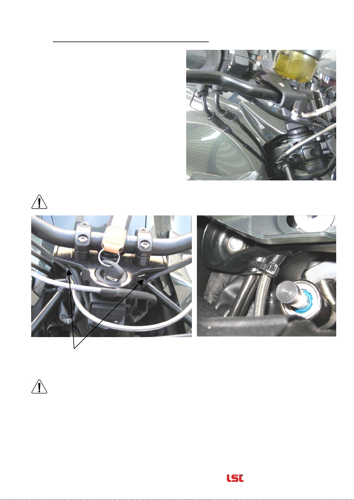
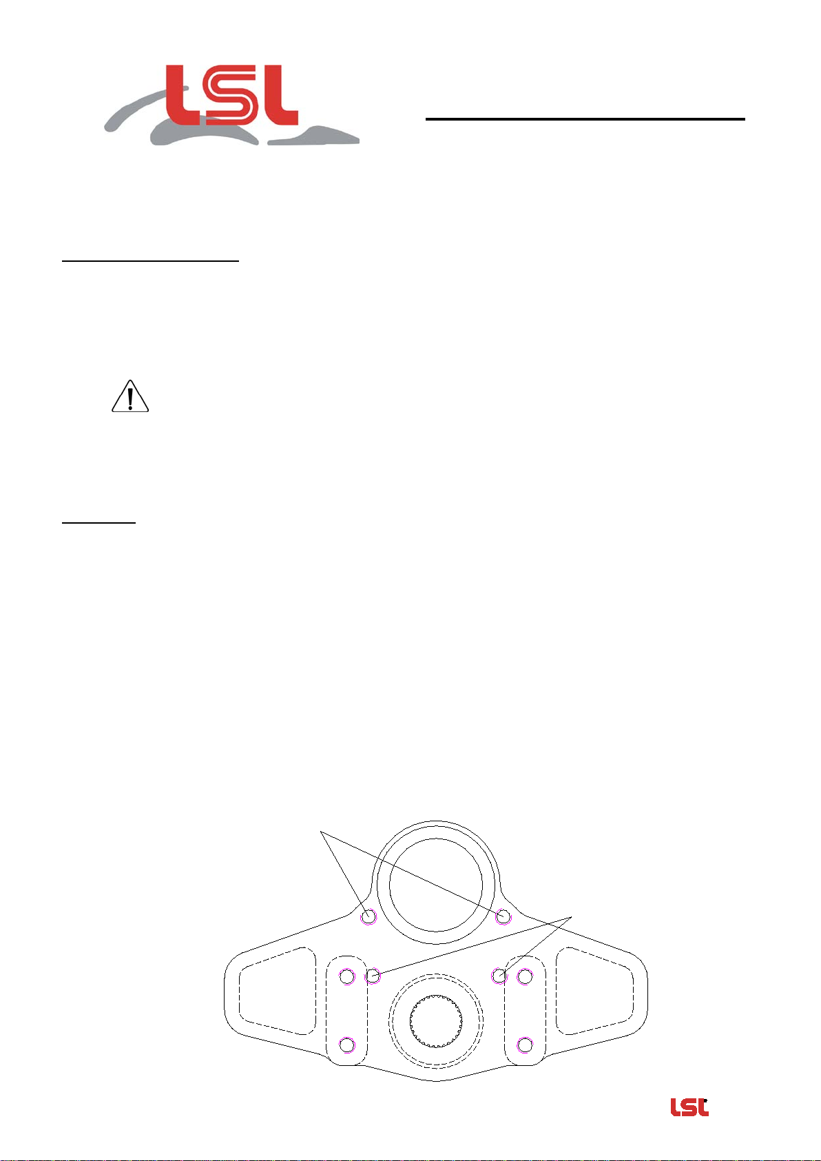
Gabelbrücke gegen Superbike-Gabelbrücke austauschen. Zur Demontage des Zündschlosses
müssen die Köpfe der Abreißschrauben aufgebohrt werden. Die beiliegenden Buchsen (l=12mm)
mit den Schrauben (M8x25) als Lenkanschläge mit Schraubensicherungsmittel an die
Gabelbrücke montieren. Zündschloss mit beiliegenden Buchsen (l=23,5mm) und neuen
Schrauben (M8x45) an der Gabelbrücke montieren. Sperrzahnscheiben als Schraubensicherung
unter den Schraubenkopf legen. Der Innensechskant der Befestigungsschrauben des
Zündschlosses sollte zur Diebstahlsicherung ausgebohrt werden. Die Steuerkopfmutter nach
Herstellerangaben mit vorgeschriebenem Drehmoment anziehen.
Gabelbrücke, Ansicht von unten
Zündschloß mit
M8x45 und
Buchsen
(l=23,5mm)
montieren
Lenkanschläge
mit M8x25
und Buchsen
(l=12mm)
montieren

——————————————————— Zubehör von —Das Original ——
Rev. 00 18/04/2012 Seite 2 von 3
Vorgeschriebener Lenkertyp: LSL Fat Bar-Lenker, flach / Typ XN1
Neuen Lenker, Typ XN1 in den Klemmböcken montieren. Lenkerklemmböcke gleichmäßig
anziehen und nach Abschluss der gesamten Montage mit Anzugsmoment 25Nm festziehen.
Montieren Sie Griffe und Armaturen wie abgebildet und positionieren Sie die Brems- und
Kupplungseinheit mit ca. 25mm Abstand zu den Armaturen.
Kontrollieren Sie bei druckloser Bremse, ob sich der Bremshebel bis zum Griff ziehen lässt
und keinesfalls vorher am Schaltergehäuse anschlägt!
Prüfen Sie vor der endfesten Montage aller Bauteile den Freigang zu Tank und Verkleidung und
korrigieren Sie bei Bedarf die Ausrichtung von Lenker und Bedienelementen.
Zur Montage der Griffe je eine durchgehende Bohrungen Ø4,0mm bohren und die Griffe mit den
originalen Schrauben befestigen.
ca. 25mm

——————————————————— Zubehör von —Das Original ——
Rev. 00 18/04/2012 Seite 3 von 3
Verlegehinweise für Kabel, Züge und Schläuche:
Gaszüge: Die Gaszüge, wie abgebildet,
rechts, auf kürzestem Weg zur
Tankverkleidung hin verlegen. Gaszug bei
voll eingeschlagener Lenkung auf
Leichtgängigkeit prüfen.
Brems- & Kupplungsschlauch: Beide Schläuche, wie abgebildet, verlegen. Die
Kupplungsleitung oberhalb des Verkleidungshalters verlegen und mit einem Kabelbinder fixieren
(siehe , Bild oben). Kupplungsleitung und Gaszüge mit einem Kabelbinder so fixieren das
kein Kontakt zum Lenkungsdämpfer möglich ist!
Armaturenkabel: Beide Armaturenkabel an der Verzweigung abisolieren und das nach unten
führende Bougierrohr um ca. 2cm kürzen. Die Verzweigung der Kabel auseinanderspreizen und
mit Isolierband neu abdichten.
Stellen Sie sicher, dass über den gesamten Lenkeinschlag Kabel, Züge und Schläuche
spannungsfrei verlegt sind und nicht geknickt werden.
Der Hochlenkerumbau ist nun korrekt montiert. Bitte vergessen Sie nicht, das Motorrad mit der
Anbauanleitung bei einer anerkannten Prüfstelle vorzuführen und den Umbau in die
Fahrzeugpapiere eintragen zu lassen.
Wir wünschen Ihnen viel Freude beim Fahren!

LSL-Motorradtechnik GmbH • D-47809 Krefeld
www.lsl.eu

———————————————— Accessories from —The Original ——
Rev. 00 18/04/2012 Page 1 of 3
Fitting Instruction
Article-No.
:
121B029
Product
:
Super Bike Conversion Kit
Model
:
BMW BMW K1200R 2005 – 2008 / K1300R 2009
Type
:
K12R / K12S
Important:
Read this instruction manual carefully and mind all warnings and tips. You should do this work
only if you‘re qualified; otherwise we recommend this mounting to be done by a professional
workshop. Improperly mounting of this kit can reduce the driveability of the motorcycle and may be
a risk to your health and life.
Special works are marked with the following signs. Please take special care on these works.
Warning! Important mounting instruction. It shows risks to your life and health.
Tips for mounting and maintenance or to avoid damage.
Mounting:
To avert any damage from the electrical systems of your motorcycle, you should
disconnect the battery ground while installing the Superbike conversion kit.
Remove handlebar controls, clutch lever bracket and brake cylinder assy, then remove the
original handlebar.
Dismount the original top yoke and install the Superbike top yoke. To demount the ignition lock
you need to drill out the heads of the breakaway bolts. Use the attached bushings (length
12mm) in combination with the M8x25mm bolts as a steering stop. Use fluid bolt lock as
Loctite 243 or 270. Fit the ignition lock with the attached bushings (length 23,5mm), new bolts
(M8x45mm) and corrugated washers underneath the bolts heads at the LSL-yoke. You should
drill out the hexagon sockets of the bolts as theft protection. To fix top yoke, tighten steering
head up to the original torque that refers to the vehicle manufacturer’s instruction.

———————————————— Accessories from —The Original ——
Rev. 00 18/04/2012 Page 2 of 3
Required handlebar type: LSL Fat Bar flat, Type XN1
Mount new handlebar into the clamps. Evenly tighten the handlebar clamps and tighten them
with 25Nm / 18.44lbf ft torque after the whole fitment is done.
Mount the handlebar controls and levers as shown and install the brake and clutch units
with approximately 25mm spacing to the controls, as shown.
Assure (without brake pressure) that the brake lever can be drawn up to the grip and
doesn’t contact the handlebar controls before. (Loosening one calliper and wobble it on
the disk to push the pistons back should be the easiest way.)
Check clearance between fuel tank and handlebar as well as to the fairing; readjust handlebar
and controls if necessary.
To fit the grips, drill an end-to-end hole (Ø4.0mm) on each side and fix the grips with the
original bolts.
ca. 25mm

———————————————— Accessories from —The Original ——
Rev. 00 18/04/2012 Page 3 of 3
Installation notes for wires, cables and hoses:
Throttle cable: Route the throttle cable, as
shown, on the shortest way to the tank
cover. Check throttle cable for free
movement on every steering angle.
Brake and Clutch hoses: Route them as shown in the picture. Lay clutch hose above the
fairing support and fix it with a cable tie (see in the picture above). Fix throttle cables and
clutch hose with a cable tie so they won’t touch the steering damper!
Handlebar Control harnesses: Unwrap the harnesses at the branching points and shorten
the down leading tubes by 2cm. Spread the wires and seal the new branching points with
insulating tape.
Make sure that no cable, hose or harness is bended and stays tension-free over the
whole steering angle.
The Superbike Conversion kit is now installed correctly.
We, the team of LSL Motorradtechnik Germany, wish you enjoyable driving!

LSL-Motorradtechnik GmbH • D-47809 Krefeld
www.lsl.eu

——————————— Equipements et Accessoires d'origines ——
Rev. 00 18/04/2012 Page 1 sur 3
Instructions de montage
N°article
:
121B029
Produit
:
Kit Street Bike
Application
:
BMW K1200R2005 – 2008 / K1300R2009
Type
:
K12R / K12S
Mentions importantes:
Lisez attentivement les instructions de montage et tenez compte des directives de sécurité.
Si vous n’êtes pas mécanicien, nous vous recommandons le montage dans un atelier spécialisé.
Le montage incorrect peut influencer la conduite de manière négative et mettre en danger votre
santé et votre vie.
Soyez attentif aux symboles suivants et suivez les directives.
Attention! Directive de montage importante: Signale un danger pouvant atteindre
votre santé ou votre vie.
Information facilitant le montage et l’entretien ou prévenant des dommages
possibles.
Montage:
Coupez le circuit électrique en débranchant le pôle négatif de la batterie pour protéger le
système électrique pendant le montage.
Démontez les poignées, les leviers, les contacteurs et les réservoirs de liquide de frein et
d’embrayage.
Remplacez le té de fourche d’origine par le té de fourche du kit Street-Bike. Percez les têtes des
vis de fixation du contacteur d’allumage pour pouvoir le démonter. Fixez le contacteur au té de
fourche avec les entretoises (l=23,5mm) et les vis (M8x45). Posez les rondelles dentelées sous
les têtes de vis pour les bloquer. Percez les têtes cylindriques à six pans des vis de fixation du
contacteur d’allumage comme sécurité contre le vol. Serrez l’écrou central au couple de serrage
indiqué par le fabricant.
Té de fourche, vue depuis en-dessous
montez le
contacteur à clé
avec les vis
M8x45 et les
entretoises
(l=23,5mm)
montez les butoirs
de direction avec
les vis M8x25 et
les entretoises
(l=12mm)

——————————— Equipements et Accessoires d'origines ——
Rev. 00 18/04/2012 Page 2 sur 3
Guidon prescrit: LSL Fat Bar, plat / Type XN1
Fixez le nouveau guidon, typeXN1, dans les pontets. Vissez les vis des pontets de manière
régulière puis serrez à un couple de serrage de 25Nm.
Posez les poignées et les commutateurs, comme indiqué ci-dessous et positionnez les
leviers de frein et d’embrayage à 25mm des commutateurs.
En cas de frein dépressurisé, contrôlez s’il est possible de tirer le levier de frein jusqu’à la
poignée sans toucher les commutateurs!
Contrôlez la liberté de mouvement par rapport au carénage et au réservoir d’essence pendant le
braquage gauche/droite et ajustez le guidon ou les commandes, si nécessaire.
Pour le montage des poignées, percez un trou de Ø4,0mm et fixez les poignées avec les vis
d’origines.
ca. 25mm

——————————— Equipements et Accessoires d'origines ——
Rev. 00 18/04/2012 Page 3 sur 3
Schéma de pose pour câbles et flexibles:
Câbles de gaz: Posez les câbles à droite,
comme indiqué ci-contre, en prenant le
chemin le plus court vers l’habillage du
réservoir d’essence. Contrôlez la souplesse
du câble pendant le braquage gauche/droite.
Durits de frein&d’embrayage: Montez les durits comme indiquées. Passez la durit d’embrayage
par-dessus du support du carénage et fixez-le avec un serre-fils (voir , image ci-dessus).
Fixez la durit d’embrayage et les câbles des gaz de façon à empêcher le contact avec
l’amortisseur de direction !
Câbles électriques:Isolez les deux câbles et raccourcissez la gaine dirigée vers le bas d’environ
2cm. Ecartez les câbles au branchement et isolez à nouveau les deux parties avec de la bande
isolante.
Contrôlez que câbles ou flexibles soient posés sans tensions ni pliures pendant le
braquage gauche/droite.
Nous vous souhaitons bonne route!

LSL-Motorradtechnik GmbH • D-47809 Krefeld
www.lsl.eu
Other manuals for K12R
1
This manual suits for next models
2
Table of contents
Languages:
Other LSL Motorcycle Accessories manuals