Lumag RPi11N User manual

Distribution Limited
Compactor Wacker Plate
Operator’s Manual
RPi11N
FOR YOUR SAFETY
READ AND UNDERSTAND THE ENTIRE MANUAL
BEFORE OPERATING THIS MACHINE


Warranty Registration Form
For the warranty to be valid the Warranty Registration Form must be completed and
returned to Lumag Distribution Limited within 14 days of the purchase, together
with a copy of the purchase invoice.
We will use your email to confirm that we have received the completed Warranty
Registration Form and contact you about any errors or omissions on the form. We
may occasionally use this email address to make you aware of news, technical advice
and special offers. If you do not wish to receive such emails please tick this box.
Unit 10, Hatchmoor Industrial Estate, Hatherleigh, Okehampton, Devon EX20 3LP
www.lumag-gb.co.uk 01837 811741
Lumag Distribution Limited Company Number: 09267547 VAT Number: GB154566788 Hatherleigh
Plant and Tool Hire is a trading name of Lumag Distribution LTD
Model:
Serial Number:
Type of Use: Business / Domesc
Name:
Business Name:
Address:
Email Address:
Phone Number:
Date of Purchase:
Place of Purchase:
Proof of Purchase
enclosed:
Distribution Limited


Distribution Limited
Lumag Servicing and Maintenance Schedules
Engine Service & Maintenance Schedule
Machine Service & Maintenance Schedule
Item Checks/Work Each Use 20hrs
(1st Month)
50hrs
(2nd Month)
100hrs
(6th Month)
300hrs
(Yearly)
Engine Oil Check Level X
Change X (1) X
Air Filter Check X
Clean X (3)
Replace X (4)
Sediment Cup Clean X
Spark Plug Check/Clean X
Replace X
Idle Speed Check/Adjust X (2)
Valve Clearance Check/Adjust X (2)
Fuel Tank Strainer Check/Clean X (2)
Combuster Chamber Inspect/Clean X (2)
Fuel Lines Check X (2)
Item Checks/Work Each Use Weekly 20hrs
(1st Month)
50hrs
(2nd Month)
100hrs
(6th Month)
300hrs
(Yearly)
Vibraon Oil Check Level X
Oil Change X (1) (2) X (2)
Fasteners Tension Check X
Clean Machine Check X
Inspect Clutch Check/Adjust X (2)
Drive Belt Check/Adjust X
Replace X (2)
All Other Moving
Parts & Cables
Lubricate X X (2)
Engine Oil 600ml Lumag Engine 1
Vibraon Case Oil 250ml Lumag Trans 1
1 – First service only, 2 = Should be carried out by your Lumag Dealer, 3 = May need to be done more
often in dusty areas & 4 = Replace paper element only
To maximise the life of your Lumag machine it needs to be serviced and maintained at every
indicated month or operating hour interval, whichever comes first, in accordance with the
below Schedules. Please note that failure to service your machine on schedule or use genuine
Lumag parts and consumables will result in your warranty being void.

Distribution Limited
Service & Maintenance Record
Product Details: Model: __________________________________
Serial number: ____________________________
Purchase Date: ____________________________
Date: Description of checks/work carried out: Parts Used?
Y/N
Parts Invoice
Number:
Dealers
Name:
Engineers
Name:
Engineers
Signature:
Please note that failure to service your machine on schedule or use genuine
Lumag parts and consumables will result in your warranty being void

2
CONTENTS .
Introduction…………………………………………………………………………………………… 2
Applications…………………………………………………………………………………………… 2
Structure…………………………………………………………………………………………………3
Functions and controls………………………………………………………………………………… 3
Accessories………………………………………………………………………………………………3
For safety operation………………………………………………………………………………………3
Hazards and risks…………………………………………………………………………………………4
Operation…………………………………………………………………………………………………6
Careand preventive maintenance ………………………………………………………………………12
Service …………………………………………………………………………………………………12
Specifications ………………………………………………………………………………………… 12
Troubleshooting ……………………………………………………………………………………… 13
Replacement and parts list …………………………………………………………………………… 13
INTRODUCTION .
Thank you for your selection of our equipment.
We have taken care in the design, manufacture and testing of this product. Should service or spare parts be
required, prompt and efficient service is available from our branches.
General Safety instructions for the Operation of Power Equipment. Our factory’s goal is to produce power
equipment that helps the operator work safely and efficiently. The most important safety device for this or
any tool is the operator. Care and good judgement are the best protection against injury. All possible
hazards cannot be covered here, but we have tried to highlight some of the important items, individuals
should look for and obey Caution, Warning and Danger signs placed on equipment, and displayed in the
workplace. Operators should read and follow safety instructions packed with each product.
Learn how each machine works. Even if you have previously used similar machines, carefully check out
each machine before you use it .Get the “feel” of it and know its capabilities, limitations, potential hazards,
how it operates, and how it stops. We has no duty if person don’t operate as instruction said.
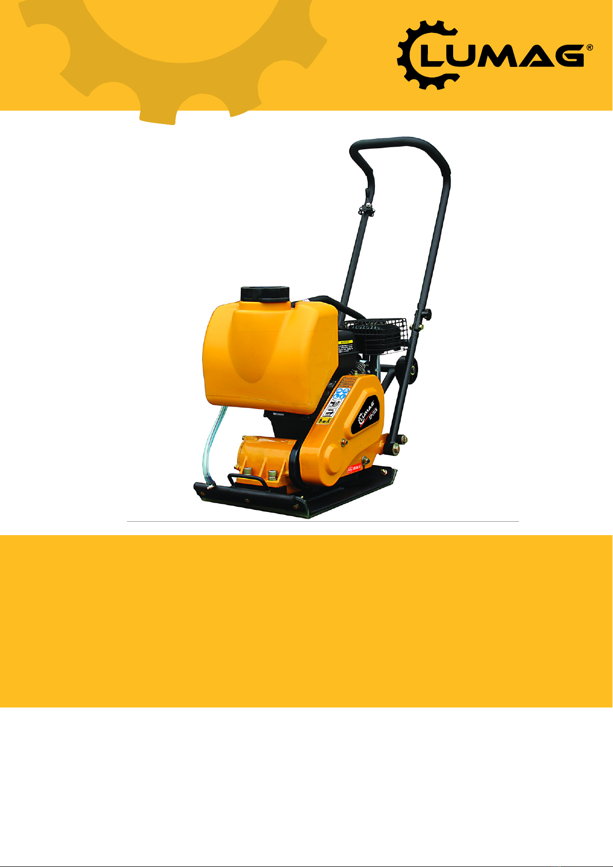
APPLICATIONS
Plate compactor is the machine that compacts the ground and it intends to make the surface smooth, by
transmitting vibration through vibrating plate, which power generated from single motor in vibrator case
This machine is suitable for making the ground surface smooth, such as leveling the soil and beaching,
finishing the asphalt paving. Applications as followings:
Trench compaction Earth works
Road maintenance Landscaping
Brickpaving Driveway toppings
! Warning for incorrect application and abuse
This machine is hard to move forward on a soil with much water (especially clay soil).It is not suitable for
such application. This machine is difficult to level a ground include big stones due to insufficient
compacting force. Plate compactor is mainly applied for compacting surface smooth and it is nor effective
for jobs that requires heavy compaction. In case of compacting ground deeply into lower layer, it is
recommended to use. Tamping Rammer, Vibro Compactor and Vibration Roller which compacting force is

3
rather effective.Please use this compactor for compacting surface on soil, sediment, sand , beaching and
asphalt. It is not recommended for use this machine for the other applications.
STRUCTURE
The upper part is made up of Power Source, Handle ,Belt Cover and Guard Hook which are fixed by Engine
base. The Engine base is fixed on Vibrating Plate by Shock Absorbing Ruber.The lower part is made up of
Vibrating Plate and Vibrator unit that has an Eccentric rotary shaft built in. The power source is transmitted
from the centrifugal clutch on engine output shaft to the eccentric rotary shaft via V-belt.
Power Transfer
Air-cooled single cylinder engine is amounted as power source and Centrifugal Clutch is fixed on engine
output shaft. Petrol Engine(2 cycle, 4 cycle) and Diesel Gasoline Engine can be mounted as option.
Centrifugal Clutch engages by running up the engine and engine is reduced o suitable number for
compacting. The rotation of engine is transmitted from V-pulley integrated with Clutch drum to Vibrator
pulley through V-belt. Vibrator Pulley rotates Eccentric rotor shaft that is contained in Vibrator case. The
generated vibration created from eccentric rotor is transmitted to Compaction with the weight of the
machine makes the compaction of the ground possible.
FUNCTIONS AND CONTROLS
Motor
The motor is controlled by an ON/OFF switch or push button which is mounted on the motor below the fuel
tank.
The motor speed is controlled by a remote throttle lever which is mounted on the machine handle.
Honda and Kama motors are fitted with an oil alert device which will stop the motor or prevent starting
when the crankcase oil level falls below a safe level
Drive belt
Tension of the drive belt is adjustable. Loosen the four nuts on the bolts which secure the motor to the
baseplate, Adjust the set screws which bear against the motor crankcase to achieve the required belt
tension .Ensure that the four nuts and the set screw locknuts are tightened after adjustment.
FOR SAFETY OPERATION
! This safety alert symbol identifies important safety messages throughout this manual and on the
machine.
When you see this symbol, carefully read the message that follows. Your safety is at stake!
Foreword:
It is important to read this manual carefully so that you will fully understand the operational characteristics
and performance of the plate compactor, Proper mainternance procedures will insure long life and top
performance of the unit.
Safety:
This section outlines basic safety procedures that apply to the operation,maintenance and adjustment of the
plate compactor. This unit is designed as a powerful, productive machine that should be operated with

4
respect and caution.
Misuse or carelessness can result in serious injury or damage. or both. Safety precautions must be observed
at all times.
Operator Qualifications:
Before operating this equipment, an individual should read this manual. Whenever possible, he should be
shown how to operate the unit by an experienced operator. Inexperience is hazardous in operating any
machine or attachment. Trial and error is not the way to become familiar with a piece of equipment. This is
expensive, cuts equipment life and can create machine should not be left unattended when operating.
General Safety:
! CAUTION
Protection required. Wear hard hat, shatterproof glassed, steel toed boots and other protective devices
required by job conditions. Avoid jewelry or loose clothing. These many catch on controls or in moving
parts and cause serious injury.
Starting Safety:
! CAUTION
Poisonous fumes. Start and operate only in well ventilated area. Breathing exhaust gases can result in
sickness or death.
Sevicing Safety:
! CAUTION
Flammable liquid. Stop engine and do not smoke or allow work in immediate area when refueling. Fire or
explosion could result from flames or sparks.
Moving parts. Shutdown engine before performing. Service or maintenanace. Contact with moving parts
can cause serious injury.
Fligh temperature. Alow machine and engine to cool before performing service or maintenance. Contact
with hot components can cause serious bums.
Engine
See engine operations manual
SHUTDOWN
EMERGENCY SHUTDOWN
Move throttle lever to “OFF” positon and also turn stop switch to “OFF”.
NORMAL SHUTDOWN
Move throttle lever quickly from “ON” to “OFF” and run engine for 3 to 5 minutes at low speed. After
engine cools,ture stopswitch to “OFF” positon, Close fuel shutoff valve.
HAZARDS AND RISKS
NEVER allow any person to operate the machine without adequate instruction .
ENSURE all operators read,understand and follow the operating instructions

5
SERIOUS INJURY could result from improper or careless use of this machine
Plate compactors are heavy units and should be positioned by two people of appropriate strength. Using the
lifting handles provided on the machine, along with correct lifting techniques.
! MECHANICAL HAZARDS
DO NOT operate the machine unless all protective guards are in place.
KEEP hands and feet clear of rotating and moving parts as they will cause injury if contacted.
ENSURE that the motor operation switch is in the OFF position and the spark plug ignition lead is
disconnected before removing the guards or making adjustments.
ENSURE both the machine and the operator are stable by setting up on level terrain and the machine will
not tip over, slide or fall while in operation or unatrttended.
DO NOT leave the machine in operation while it is unattended.
ENSURE that the walls of a trench are stable and will not collapse due to the action of the vibration ,prior to
commencing compaction.
ENSURE that the area to be compacted does not contain any “live” electrical cables, gas, water or
communication services which may be damaged by the action of the vibration.
EXERCISE CARE when operating unit. Exposure to vibration or repetitive work actions may be harmful to
hands and arms.
NEVER stand on the unit while it is operating.
DO NOT increase the governed no-load motor speed above 3.500 r/min. Any increase may result in
personal injury and damage to the machine.
BE CAREFUL not to contact with muffler when the engine is hot, since it can cause severe burns.
ENSURE that repairs to the motor and machine are carried out by specialists.
! FIRE & EXPLOSION HAZARDS
PETROL is extremely flammable and explosive under certain conditions.
ENSURE that petrol is only stored in an approved storage container.
DO NOT refuel the motor while it is in operation or hot.
DO NOT refuel the motor in the vicinity of sparks, a naked flame or a person smoking.

6
DO NOT over fill the fuel tank and avoid spilling petrol when refueling. Spilled petrol or petrol vapour may
ignite. If spillage occurs,ensure that the area is dry before starting the motor.
ENSURE theat the fuel tank cap is securely fitted after refueling.
! CHEMICAL HAZARDS
DO NOT operate or refuel a petrol or diesel motor in a confined area without adequate ventilation.
CARBON MONOXIDE exhaust gases from internal combustion motor driven units can cause death in
confined spaces.
! NOISE HAZARDS
EXCESSIVE NOISE can lead to temporary or permanent loss of hearing.
WEAR an approved hearing protection device to limit noise exposure. As required by Occupational Health
and Safety regulations.
WEAR an approved hearing protection device to limit noise exposure. As requrede by Occupational Health
and Safety regulations.
PROTECTIVE CLOTHING
ALWAYS wear approved hearing protection when working in a confined work space. Protective goggles
and a dust mask should be worn when working in a dusty environment. Protective clothing and footwear
may also be desirable wheh working with hot mix bitumen.
! ADDITIONAL HAZARDS
Slip/Trip/Fall is a major cause of serious injury or death. Beware of uneven or slippery work surfaces.
Exercise care when working in the vicinity of unprotected holes or excavations.
OPERATION
GENERAL OPERATION
The machine is best suited to the compaction of bituminous and granular materials e.g. granular soils,
gravels and sands or mixtures of both. Cohesive soils such as silt and clay are best compacted using the
impact force produced by a vibrating rammer.
Where possible the site should be graded and leveled before commencing compaction.
Correct moistrure content in soil is vital to proper compaction.Water acts as a lubricant to help slide soil
particles together. Too little moisture means inadequate compaction; too much moisture leaves water-filled
voids that weaken the soil’s load bearing ability.

7
Use unleaded grade petrol and ensure that the fuel is free from contamination.
The vibratory motion provides a self propelling action. Position the handle at the opposite end of the
machine to the vibrator.
Start the motor using the recoil starter. ( If the motor is fitted with an on/off switch this must first be turned
to ON before starting. )
For more information of starting and correct operating procedures of the motor, refer to the motor operation
manual supplied with the unit.
Increase the motor sped to the maximum setting using the hand throttle lever, before commencing
compacting.
The machine should be controlled by grasping the handle with both hands and applying restraint to control
the for ward notion. Forward or backward motion has problem, adjust the red handle or nut s (item 21, 22 in
components list) Steer the machine by moving the handle sideways to the right or left.
ALWAYS maintain good footing so that you do not slip and loose control when starting or operating the
machine.
1. Prior to operation
1-1. Make sure that all dirt, nut, etc., are thoroughly removed from the unit prior to operation. Special effort
should be given to the button face of the vibrating plate and those areas adjacent to the cooling air inlet
of engine, carburetor, and air cleaner.
1-2. Check all bolts and screws for tightness and make sure all bolts and screws are securely tightened.
Loose bolts and screws may cause damage to the
unit.
1-3. Check the V-belt for tightness. The normal slack
should be approximately 10-15 mm (1/2’’) when
the belts are forcibly depressed in the middle
position between the two sheaves.
If there is excess belt play. There could be a
decrease in the impact force or erratic vibration,
causing machine damage.
1-4. Check the engine oil level and if the engine oil lever
is low, it should be refilled. Use the proper motor
oil as suggested in the table below. (Fig-1)
1-5. 1-5. Remove the oil plug in the vibrator assembly
and check the oil level. Make sure the compactor is
level when checking. The oil level should be up to the oil plug. Every month or every 200 hours of
operation, replace the oil.

8
! IMPORTION
Use the motor oil SAE
When changing the oil, the old oil can be drained by
tipping the unit. The oil will drain easily while it is hot.
1-6. A regular grade gasoline should be used in the engine.
When filling the fuel tank, make sure the fuel filter is used.
2. Caution
2-1. Be careful with the operating place and ventilation.
Avoid operating the machine in a closed room, tunnel, or
other badly ventilated places, since its exhaust contains
deadly poisonous carbon monoxide. If the machine is
employed unavoidable operated in such a place, discharge
the exhaust out the room by a suitable means.
2-2. Be careful with the hot members.
Mufflers and other hot members are dangerous.
Do not touch them with unprepared hand.
2-3, Observe with the following cautions when transporting.
Clamp fuel tank cap securely, and turn the fuel have OFF at
the source during Drain gasoline from fuel tank before
transporting over a long distance or on rough roads.
2-4. Stop engine without fail before replenishing fuel
tank.
Never replenish gasoline while the engine is running or
remains hot otherwise spilled or evaporated fuel is liable to
catch fire from engine sparks or muffler heat.
Wipe off spilled fuel, if any, before starting engine. Be
careful not to spill fuel.
2-5. Keep inflammables way from the vicinity of the
exhaust port.
Be careful with gasoline match, straw and other
inflammables, since the exhaust port is subjected to a high
temperature.
3. Starting
Gasoline Engine
3-1. Turn the STOP SWITCH clock-wise to the position
“I”(ON) Fig-3
3-2.Open the fuel cock Fig-4.
3-3. Set the speed control lever 1/3 to 1/2 of the
way towards the high speed position. Fig-5
3-4. Close the choke lever.
If the engine is warm or the ambient temperature is high, open the choke lever half-way, or keep it
Fully open.

9
If the engine is cold or the ambient temperature is low, close the choke lever fully. Fig-6
3-5. Pull the starter handle slowly until resistance is felt. This is the “compression”point. Return the
handle to its original position and pull swiftly.
Do not pull out the rope all the way.
After strater the engine, allow the starter handle to
return to its original position while still holding the
handle.
Diesel Engine
3-6. Turn the throttle lever to START position (open
by about 30 degrees)
Fig-5-D
3-7. Operate Starter
In case of recoil starter
By pulling the starter knob slowly, you will reach such
point where resistance become strong (compression
point). By pulling it further, you will find a point where
resistance is reduced. Return the knob, but slowly
return it original. Fig-7-D
! CAUTION
Do not pull the rope all the way and do not take you
hand off the pulled knob but slowly return it
original position.
3-8. After starting up the engine, be sure to perform a
warm up the engine, be sure to perform a warm up run
for 2 to 3 minutes. This should be performed without
fail, particularly during winter season.
4. Operation
4-1. As the engine warms up, gradually move the
choke lever to the OPEN position Fig-8
4-2. Move the speed control lever from the LOW to the
HIGH position. When the engine speed reaches
approximately 2,300-2,600 PRM, the centrifugal clutch
engages. If the engine speed increased very slowly, it is
possible that the clutch can slip. Do not operate the
speed control lever slowly. Fig-9,10
OIL ALERT SYSTEM (Optional)
The Oil Alert Aystem is designed to prevent engine
damage caused by an insufficient amount of oil in the crankcase. Before the oil level in the crankcase can
fall below a safe limit, the Oil Alert System will automatically stop the engine (the engine switch will
remain in the ON position).
! NOTICE

10
If the engine stops and will not restart, check the engine oil level.
4-3. When compacting asphalt, it is advisable to paint the bottom face of the vibrating plate with diesel fuel.
This will assist in preventing the plate from sticking to the asphalt.
4-4. When shutting off the vibrator, turn the speed control lever from the HIGH to LOW position. Do not
move the speed control lever slowly.
5. Transportation
5-1. Be sure to stop the engine while transporting.
5-2. Screw up the fuel tank cap securely and close the fuel valve
to avoid fuel leaking.
5-3. In transportation by car, fix machine securely not to move
nor to fall down.
In case of driving for long distance or at off-road, take out fuel
from tank.
6. Shutdown
To stop the engine in an emergency, turn the stop switch to the
OFF position.
Under normal conditions, use the following procedure:
6-1. Set the speed control lever at the low speed position and
allow the engine to run at low speed for 2 or 3 minutes before
stopping.
6-2.Tum the stop switch to the OFF position. Fig-12
6-3.Close the fuel cock.Fig-13
7. Service & storage
! CAUTION
Flammable liquid: Stop engine and to not smoke or allow work in
immediate area when refueling. Fire or explosion could result
from flames or sparks.
Moving parts: Shutdown engine before performing service or
maintenance. Contact with moving parts can cause serious injury.
High temperature: Allow machine and engine to cool before
performing service or maintenance. Contact with hot components
can cause serious burn.
7-1. Daily Service
A. Remove mud, dirt, ect, from the unit.
B. Clean bottom face of the vibrating plate.
C. Check the air cleaner element and clean if necessary.
D. Check all nuts, bolts, and screws for tightness and retighten as
necessary.
7-2. Weekly Service

11
A. AIR CLEANER SERVICE Fig-14
Dirty air cleaner element will cause starting difficulty, power loss, engine malfunctions, and shorten engine
life extremely.
Keep the air cleaner element clean.
URETHANE FOAM ELEMENT
Remove the element and wash it in kerosene or diesel fuel. Then saturate it in a mixture of 3 parts kerosene
or diesel fuel and 1 part engine oil. Squeeze the element to remove the mixture and install it in the air
cleaner.
URETHANE FOAM DUAL STRUCTURE
1. Clean the urethane foam in the same way as
described above.
2. Wash the element in kerosene or diesel fuel.
Saturate it in a mixture of 3 parts kerosene or diesel
fuel and 1 part engine oil. Shake off excessive oil
and reinstall.
B. Remove spark plug, clean and adjust the spark
plug gap to 0.6-0.7mm(0.02-0.03 in.). Fig-15
C. Drain the motor oil of the engine and replace
with new specified oil. Fig-16
! NOTE: When the engine is new, the first oil
change must be made after 20 hours of operation
and replenish the oil tank before operating.
7-3. Monthly Service
Change the oil in the vibrator assembly.
7-4. Storage
When storing the compactor for long periods after
operation.
A. Thoroughly drain the fuel from the fuel tank fuel
pipe and carburetor.
B. Pour a few drops of motor oil into the cylinder
by removing the spark plug. Rotate the engine
several times by hand so that the cylinder interior is
covered with oil.
C. Clean the outer surface of the machine with an
oil moistened cloth. Cover the unit and store in a
humidity-free area.

12
CARE AND PREVENTIVE MAINTENANCE
Check the oil level in the motor crankcase daily. Check the vibrator oil level weekly. Inspect the rubber anti
vibration mounts for wear or deterioration. Clean the underside of the plate regularly to prevent a build up
of material.
SERVICE
Change the oil in the motor crankcase regularly to minimize wear. Inspect, clean and / or replace the motor
air cleaner regularly, particularly when operating in a dusty environment. Inspect, clean and / or replace the
spark plug regularly Check all fasteners for tightness as the machine is subiect to vibration. Check vee belt
tension, wear and that it is running true. Adjust or replace as required.
Vibrator oil check
1. Place the plate compactor horizontally on a flat surface. Make sure the compactor is level when
checking the oil in the vibrator assembly.
2. Check vibrator oil level by removing the plug (vibrator oil
gauge) as shown in Fig-17.
The oil level should be up to the pil plug. If oil is required,
replace using SAE motor oil, as suggested in the table Fig-1.
3. When changing the vibrator oil, remove the drain plug(Fig-17),
and simply tip the compactor to drain the oil. Note that the oil
will drain more easily while it is hot.
SPECIFICATIONS
Model
CNP10-1
CNP10-2
Engine
Air-cooled,4-cycle, single cylinder
Engine type
Petrol , Honda GX160
Chinese Petrol Engine
Power kw(hp)
4.0(5.5)
Weight kg(lbs)
64(140)
Frequency vpm
5600
Centrifugal Force kn
10.5
Compaction Depth cm(in)
20(8)
Travel Speed cm/s(in/s)
40(16)
Efficiency m2/hr(ft2/hr)
450(4800)
Plate Size cm(in)
50*36(20*14)
Dimension cm(in)
69*38*62(27*15*24)

13
TROUBLESHOOTING
SYMPTOM POSSIBLE CAUSES AND CORRECTION
Motor will not start
-Check the ON/OFF switch to ensure that it is switched ‘ON’.
-Check the fuel supply.
-If a Honda or Kama motor is fitted check the crankcase oil level as and oil
sensor device is fitted to these motors which prevents starting and stops the
motor when the oil level is low.
-Ensure the carburetor jet and bowl to ensure they are than.
Motor stops
-Check the fuel supply.
-Check that the fuel cock is turned on.
-Check the condition of the air filter.
Petrol Motor lacks power.
-Check the condition of the air filter
-Check the condition of the spark plug.
Insufficient vibration
-Check for a slipping or a missing see belt.
-Check that the motor governed speed is 3.500 r/min.
Machine is not moving freely
-Check the underside of the plate for a build up of material.
REPLACEMENT AND PARTS LIST
Major components and vibrator assembly parts list as followings.

14

15
•Major components list
PART NO.
DESCRIPTION
100001
Engine
100002
the upper half of Handle(Optional )
100003
locknut M10(Optional )
100004
Washer ¢10(Optional )
100005
Washer ¢10(Optional )
100006
Hexagonal bolt M10*35(Optional )
100007
Offset ring bolt M10(Optional )
100008
the lower half of Handle(Optional )
100009
Rubber
100010
Spring washer ¢12
100011
Washer ¢12.5*40*3
100012
Hexagonal bolt M12*65
100013
Clutch assembly
100014
Washer ¢8
100015
Spring washer ¢8
100016
Hexagonal bolt M8*25
100017
dust-proof plate
100018
Belt cover
100019
protective frame(Optional )
100020
clamp
100021
Base
100022
clamp ring ¢17(Optional )
100023
Washer ¢17(Optional )
100024
Wheel (Optional )
100025
bracket of trolley wheels(Optional )
100026
Vibrator assembly
100027
Vibrating plate
100028
Shock absorber
100029
Washer ¢10
100030
spring washer ¢10
100031
Cap nut M10
100032
Throttle lever
100033
Dragline
100034
V-belt
100035
flat key
100038
stranding screw M10*35
100039
Washer ¢16
100040
Spring washer ¢16
100041
socked head bolt M16*55
100042
Hexagonal bolt M12*50
100043
Washer ¢12
Table of contents
Other Lumag Construction Equipment manuals

Lumag
Lumag RP300 User manual

Lumag
Lumag RP1100 PRO User manual

Lumag
Lumag RP130HPC User manual

Lumag
Lumag LVS80-GX User manual

Lumag
Lumag MD350/GX User manual

Lumag
Lumag MD300R User manual

Lumag
Lumag LFR40 User manual

Lumag
Lumag EB400PRO User manual

Lumag
Lumag MD500E User manual

Lumag
Lumag RPi31DE User manual