Lumascape Centria C2 User manual
Other Lumascape Spotlight manuals
Lumascape
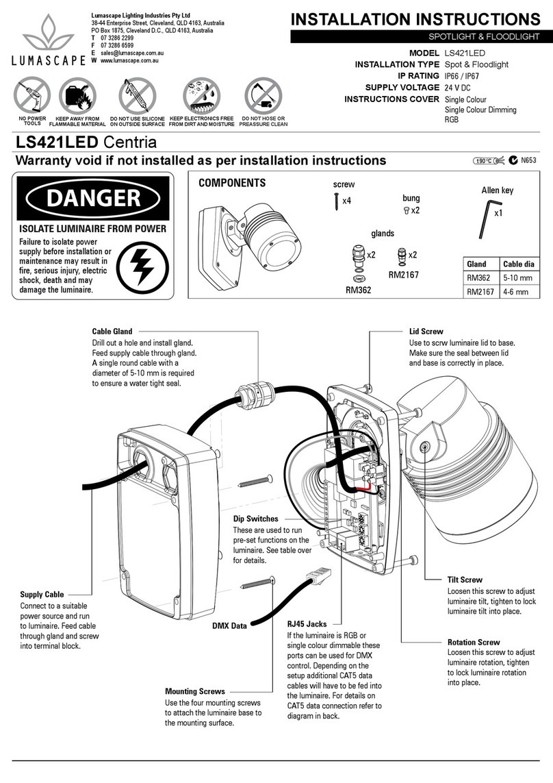
Lumascape LS421LED Centria User manual
Lumascape
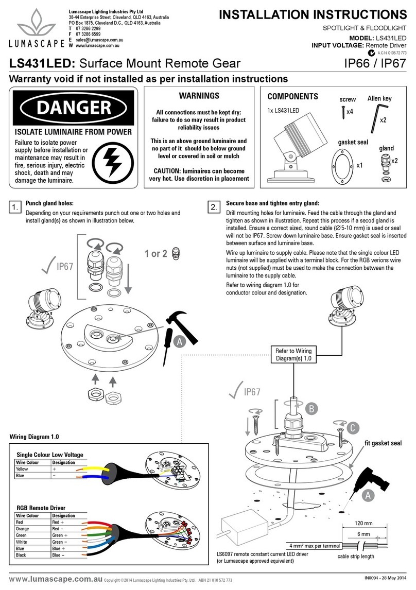
Lumascape LS431LED User manual
Lumascape
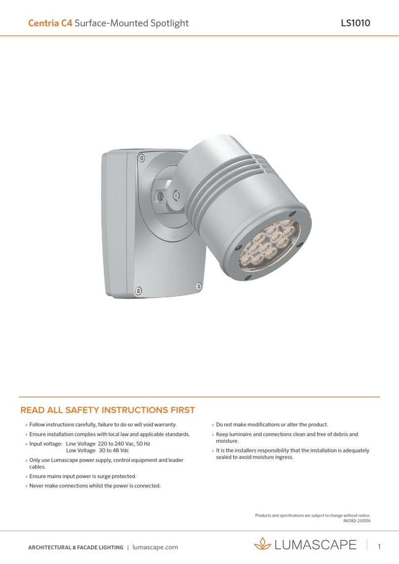
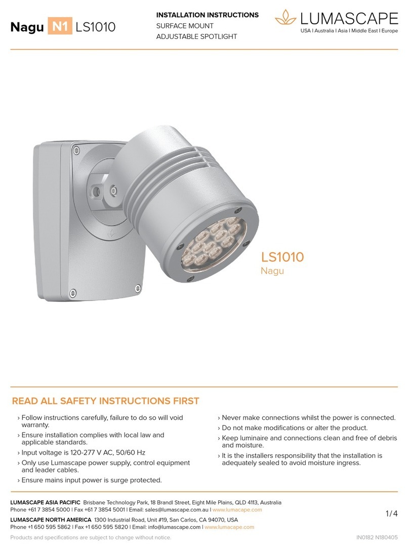
Lumascape Nagu N1 LS1010 User manual
Lumascape
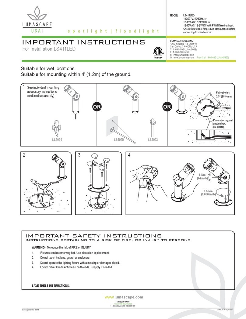
Lumascape LS411LED Guide
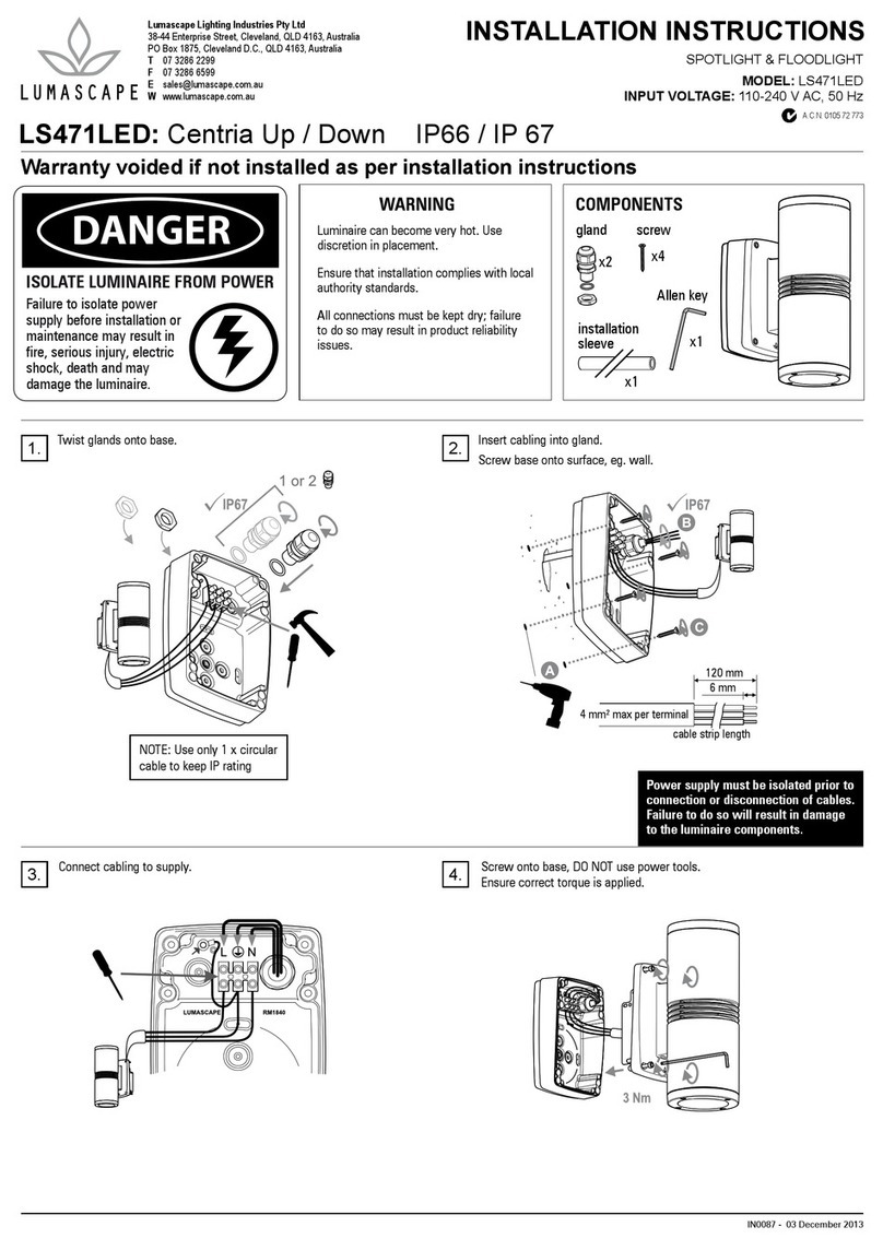
Lumascape
Lumascape LS471LED User manual
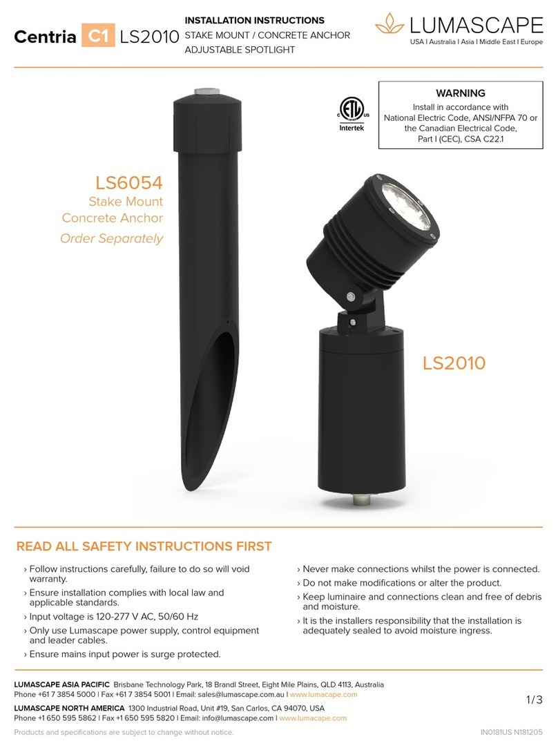
Lumascape
Lumascape Centria C1 User manual

Lumascape
Lumascape LS421LED User manual

Lumascape
Lumascape Centria C1 User manual
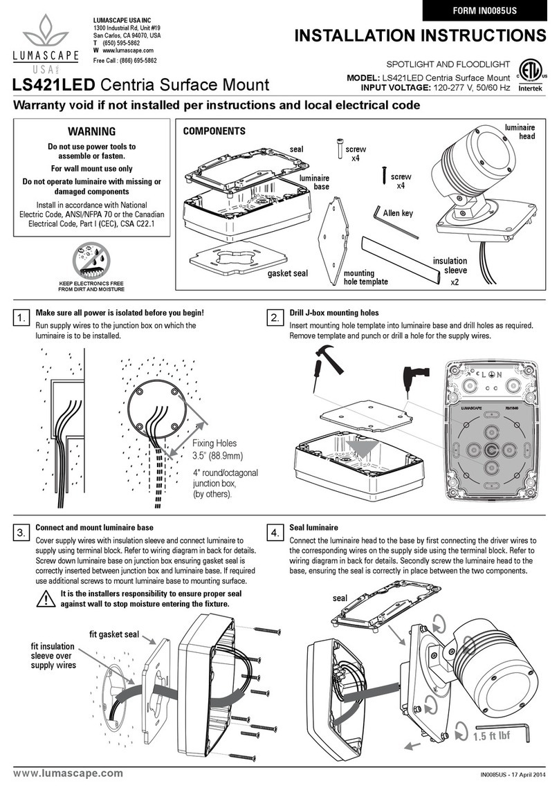
Lumascape
Lumascape LS421LED User manual

Lumascape
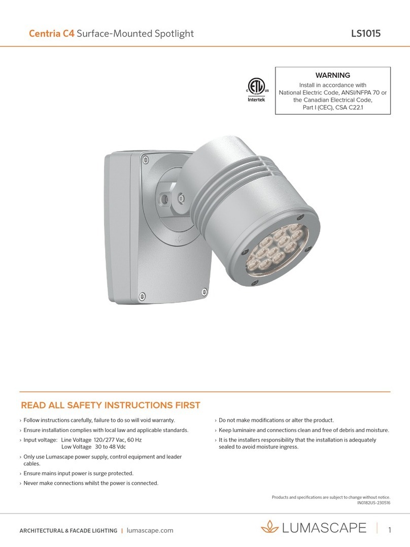
Lumascape Centria C4 User manual
Popular Spotlight manuals by other brands

Guangzhou Yinhe Lighting&Sound Equipment Factory
Guangzhou Yinhe Lighting&Sound Equipment Factory NE-204 user manual

LIVARNO home
LIVARNO home 375304 2101 Installation, operating and safety information
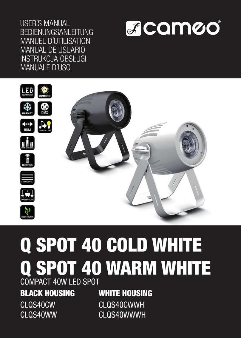
Cameo
Cameo CLQS40WW user manual
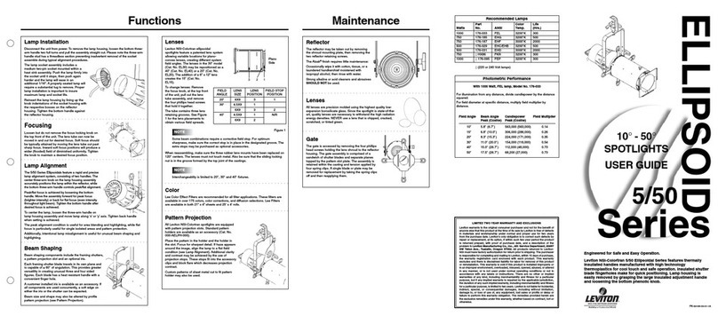
Leviton
Leviton Ellipsoid 5/50 user guide

Monacor
Monacor img Stage Line PARL-56PDX/CR instruction manual

Vector
Vector SL3AKV instruction manual
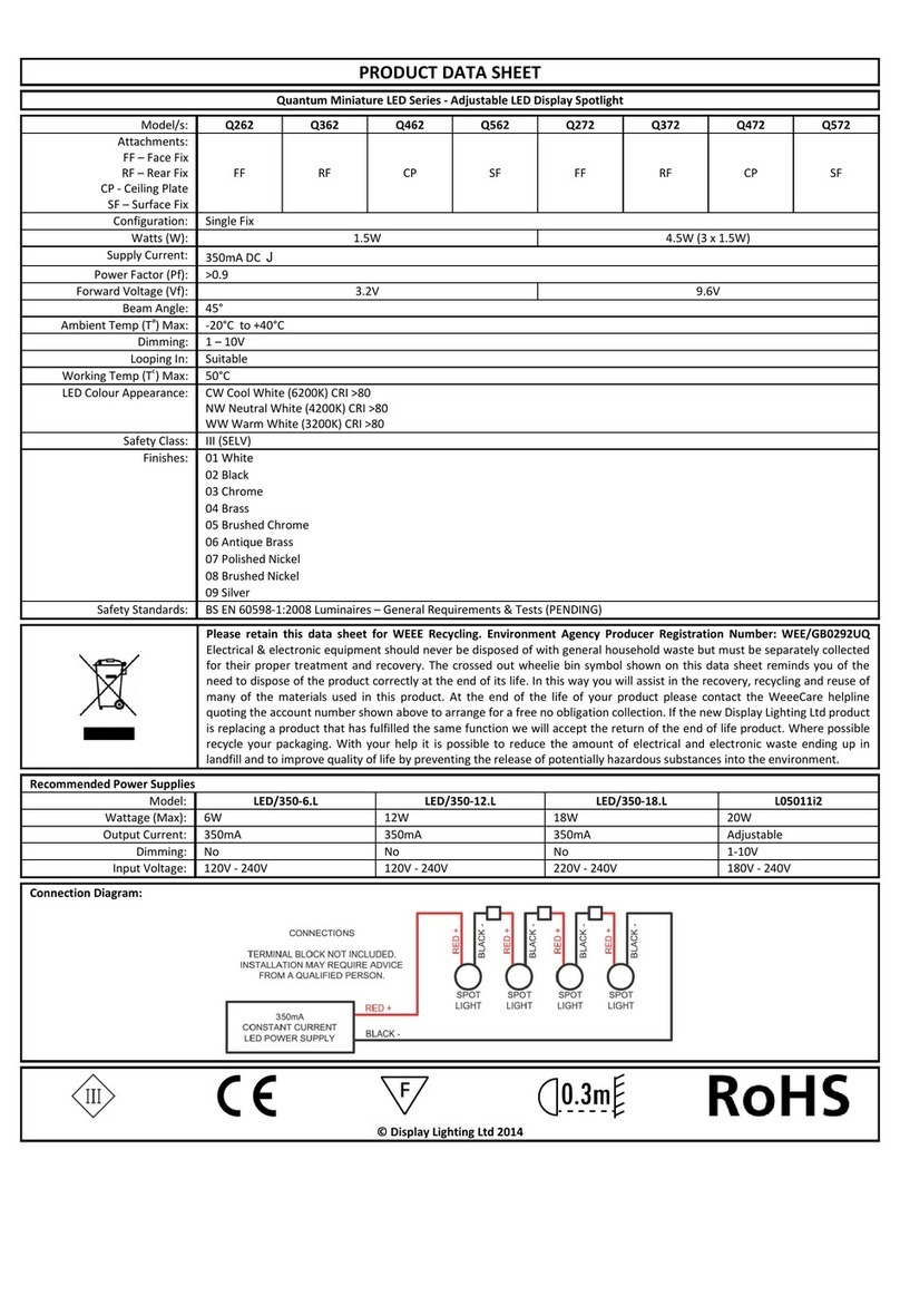
Quantum
Quantum Q262 Product data sheet
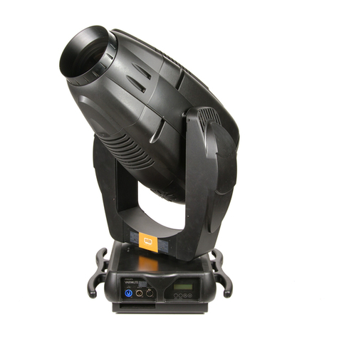
Philips
Philips Vari-lite VL3015LT user manual
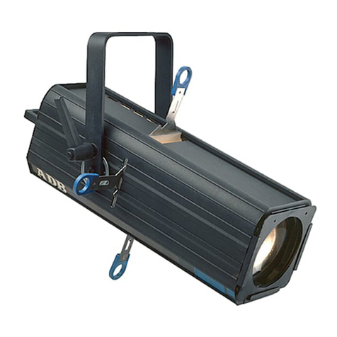
EUROSPOT
EUROSPOT C51 instruction manual
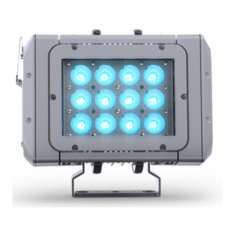
DTS
DTS MINI BRICK ARC user manual
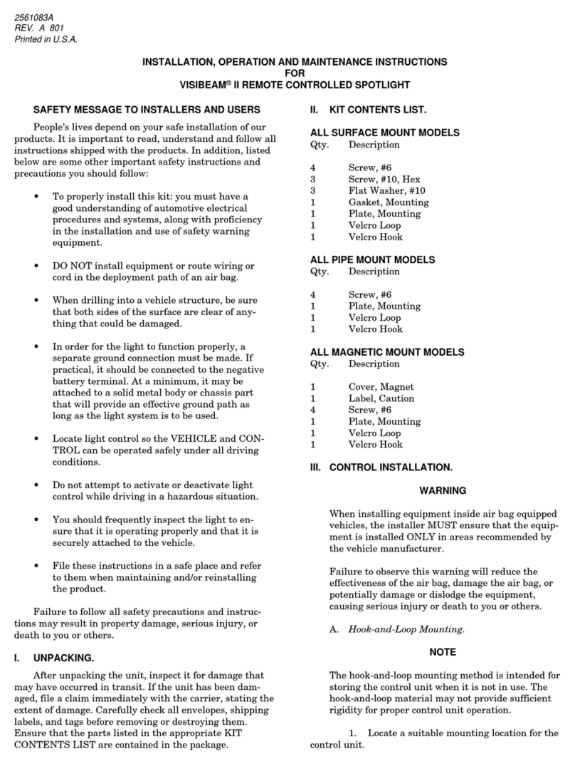
Federal Signal Corporation
Federal Signal Corporation VISIBEAM II Installation, operation and maintenance instructions

ACME
ACME LED-MS350B user manual

EuroLite
EuroLite Akku flat light 1 user manual

Commercial Electric
Commercial Electric SPTM-1401 Use and care guide
Vision & Control
Vision & Control SLB-500-W5K7-P-SL Instructions for use
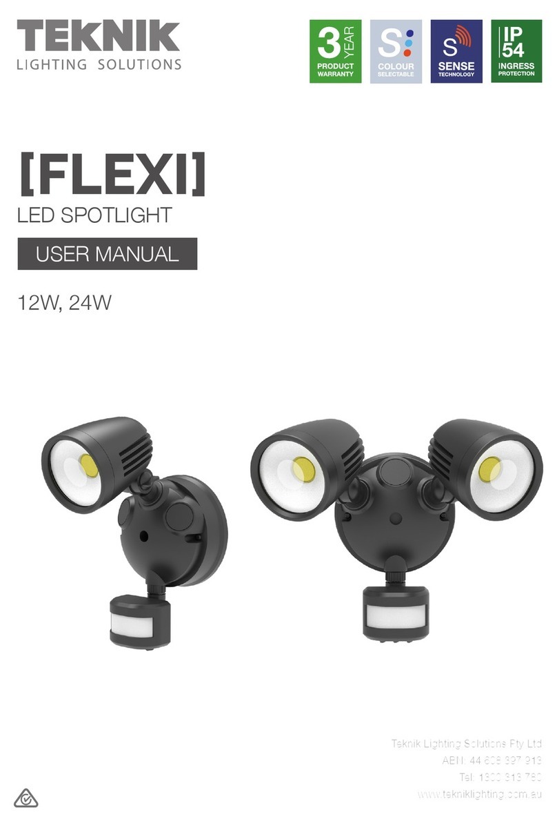
Teknik
Teknik FLEXI user manual
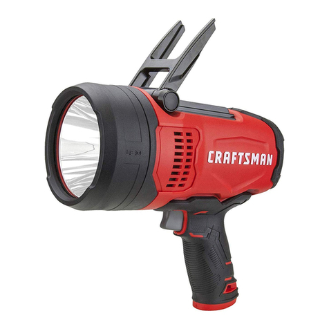
Craftsman
Craftsman CMXLSB10 instruction manual

EuroLite
EuroLite LED SLS-144 UV Floor Spot user manual
