Lumel N20ZPLUS User manual

DIGITAL PANEL METER
N20ZPLUS
USER’S MANUAL

1. APPLICATION and DESIGN of the METER.................................................................... 2
2. METER SET....................................................................................................................... 3
3. Basic requirements, operational safety ............................................................................... 3
4. Fitting.................................................................................................................................. 3
4.1. Connection diagrams ................................................................................................... 4
5. Operation............................................................................................................................. 5
5.1. Display description ...................................................................................................... 5
5.2. Messages after Switching the Supply on..................................................................... 5
5.3. Configuration of the meter .......................................................................................... 5
5.4. Parameter description .................................................................................................. 6
5.4.1. Display ................................................................................................................. 6
5.4.2. Measurement parameters...................................................................................... 6
5.4.3. Alarm parameters ................................................................................................. 8
5.4.4. Communication parameters.................................................................................. 9
5.5. Factory parameters ...................................................................................................... 9
6. MAP OF MODBUS REGISTERS................................................................................... 10
7. ERROR CODES .............................................................................................................. 14
8. TECHNICAL DATA ........................................................................................................ 14
9. ORDERING CODES ....................................................................................................... 17

N20ZPLUS-09A 2 User’s Manual
1. APPLICATION and DESIGN of the METER
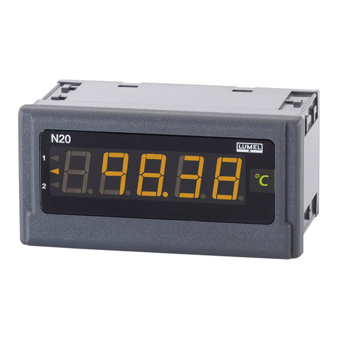
The N20ZPLUS meter is a digital programmable panel instrument designed for
measurements of a.c. voltages, a.c. currents, or frequency. The readout display is a
LED display which enables the presentation of measurements results in red, green or
orange color
The N20ZPLUS meter has a built-in RS-485 interface and the MODBUS RTU
protocol provided, by means of which it is possible to configure the meter or read the
measured values. The meter is compatible with free E-Con software available for
download on the manufacturer's website. The meter should be connected to a PC via
the RS-485 to USB converter, e.g. PD10. Parameters that can be reprogrammed are
as follows:
-display color, individually in three colour versions,
-thresholds of displayed exceedings,
- result display precision (decimal point);
- backlight;
- rtype of the measured signa, AC or AC+DC (True RMS);
- averaging time of the measurement;
-recounting of indications (individual characteristic);
- operation modes of two OC type outputs, 6 operating modes to choose;
- RS-485 transmission parameters
- MODBUS bus settings
The meter is equipped with two OC type outputs. The activation of the output
is signaled by the backlight of the triangular alarm indicator on the left side of the
display with the corresponding alarm digit. The backlight color is always different from
the color of the displayed measured value.
The degree of protection of the meter from the front side is IP65. Dimensions
96 x 48 x 64 mm (including terminals). The housing is made of self-extinguishing
plastic.
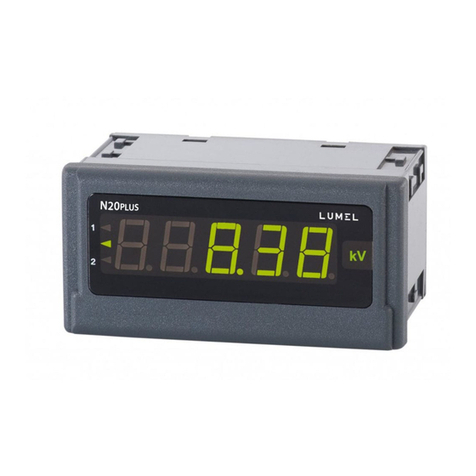
Fig.1. View of N20ZPLUS meter.

N20ZPLUS-09A 3 User’s Manual
2. METER SET
Complete set of the Analyzer includes:
- N20ZPLUS meter 1 pc.
- clamps to fix the meter in the panel 4 pcs.
3. Basic requirements, operational safety
Meaning of the symbols used in this manual:
Warning!
Warning of potentially dangerous situations. It is especially
important to read and understand these instructions before
connecting the device. Failure to meet the instructions that are
marked with this symbol can result in serious injury of
personnel and damage to the device.
Caution!
Generally useful notes. Following these instructions ensures
easy operation of the device. The user must take them into
account when the operation of the device does not meet the
user’s expectations.
Possible consequences when these instructions are not
followed!
In terms of operational safety the meter meets the requirements of EN 61010-1.
Safety instructions:
•The assembly and the installation of the electrical connections may be carried
out only by a duly qualified electrician.
•Before turning on the meter verify the connections.
•Removal of the meter housing during the warranty period voids the warranty.
•The device is intended for installation and use in industrial electromagnetic
environments.
•A switch or a circuit-breaker should be installed in the building or facility. It
should be located near the device, easily accessible to the operator, and suitably
marked.
4. Fitting
The meter has separable strips with screw terminals which enable the
connection of external wires of 2.5 mm2 cross-section. In the version for current
measurement, the plug enables a permanent fixing to the socket by means of
screws.

N20ZPLUS-09A 4 User’s Manual
A cut-out of 92+0,6 x 45+0,6 mm must be made in the panel The thickness of the
material from which the panel is made must not exceed 6 mm. The meter should be
inserted from the front of the panel with the voltage supply disconnected. Before the
insertion into the panel, one must check the correct placement of the seal. After
inserting into the hole, fix the meter by means of clamps (Fig. 2)
1
2
Fig. 2: Meter fitting
Fig. 3: Meter overall dimensions
4.1. Connection diagrams
Fig. 4: Electrical connections of the N20ZPLUS meter for voltage and frequency
measurements
Fig. 5: Electrical connections of the N20ZPLUS meter for current measurements
supply
supply

N20ZPLUS-09A 5 User’s Manual
backlit unit
measured value
instantaneous
value
display indicators
5. Operation
5.1. Display description
Fig. 6: Frontal panel
5.2. Messages after Switching the Supply on
After turning the power on, the meter displays the name of the N20Z PLUS X
meter - where X is the letter denoting the version: U- voltage measurement,
I - current measurement, F- frequency measurement, S- cutom-made version. Then
the program version is displayed in the form r x.xx - where x.xx is the number of the
current program version or the cutom-made version number.
Until the required number of correct measurements is obtained (according to
table 1), the instantaneous value from 1 measurement is displayed, signaled by the
backlit indicator of instantaneous value.
In the event of an error or exceeding the range value, the display will show the
message described in point 6. Exceeding the measurement range is additionally
signaled by the instantaneous value indicator.
5.3. Configuration of the meter
To configure the N20ZPLUS meter the user can use free eCon software
available for download on the manufacturer's website (www.lumel.com.pl). The meter
should be connected to a PC via a USB to RS-485 converter, e.g. PD10, and then in
the E-Con program, the transmission parameters in accordance with those set in the
meter should be selected.
CAUTION! Programming the meter parameters should be done with measuring
circuits disconnected !
alarm indicators

N20ZPLUS-09A 6 User’s Manual
5.4. Parameter description
5.4.1. Display
The display can be configured by changing the settings of the following
parameters:
a) display colors of the measured value. The display range is divided into three
areas separated by threshold values KpL and KpH (respectively lower threshold KpL
and upper threshold KpH of the change of the display color - Fig. 7). The color of
displayed numbers for each area is selected from three available colors: green,
orange and red. The KpL and KpH values are set by the user and refer to the
displayed value (i.e. also include individual characteristics). By default, the KpL value
is equal to 100% of the nominal value, while KpH is equal to 110% of the nominal
value, e.g.: for the 400 V meter: for KpL - 400 V and for KpH - 440 V respectively.
Caution! After setting the individual characteristic, KpL and KpH are not
automatically updated.
Fig. 7. display color configuration
b) decimal point - measurement precision. There are 5 possible display
configurations to choose from, but you should take the accuracy of the measurement
into account, for example: for the 400 V range - the measurement error is 2 V, so
choosing a precision with two decimal places does not give you more accurate
measurements. For version with voltage measurement the factory setting of precision
is 0000.0; for version with current measurement - 00,000.
c) unit backlight. Unit backlight can be turned on or off. It is on by default.
5.4.2. Measurement parameters
We can configure the measurement by changing the following:
a) input type: AC measurement, AC+DC measurement (True RMS), AC
measurement is factory default,
b) averaging time: until the required number of correct measurements is obtained
(according to table 1), the instantaneous value from 1 measurement is displayed.
After measuring a certain number of measurements, the arithmetic mean of the
measured measurements is displayed. Subsequent measurements are added on the
displayed value
KpH
KpL

N20ZPLUS-09A 7 User’s Manual
principle of "rolling window", i.e. the earliest measurement is discarded and the most
recently measured one is put in its place. Measuring values outside the measurement
range results in displaying the exceeding and starting to count correct measurements
from the beginning. The factory time is set to 1s
Table 1
Time
of measurement
Number of
averaged
measurements
Updating the displayed value
(duration of 1 measurement)
0.5 s
1
every 0.5 s
1 s
2
every 0.5 s
3 s
6
every 0.5 s
5 s
10
every 0.5 s
10 s
20
every 0.5 s
15 s
30
every 0.5 s
30 s
60
every 0.5 s
1 min
100
every 0.6 s
2 min
100
every 1.21 s
5 min
100
every 3 s
7 min
100
every 4.2 s
12 min
100
every 6 s
15 min
100
every 9.1 s
c) Thresholds for displayed exceedings: You can narrow the limits beyond which
the exceedings will be displayed, taking into account individual characteristics. If the
measured value is outside the measurement range 0 ... 120% of the nominal value
(e.g. for the 400 V version the range is 0 ... 480 V) an exceeding is displayed, the
range is factory set to
-19999 ... 99999.
d) Enabling the individual characteristics. The factory default is off. The
configuration of the individual characteristics consists in defining the points of the
linear characteristics used to convert the measured value into the displayed value
(Figure 8).
Fig. 8. Individual characteristics

N20ZPLUS-09A 8 User’s Manual
For example, to get displayed values in kV, set points X1, X2, Y1, Y2 as
follows:
X1 = 0, Y1 = 0, X2 = 1000, Y2 = 1
This record means that for each measured value in the range 0 ... 1000, the
displayed value in the range 0 ... 1 will be calculated.
After setting the points X1, Y1, X2, Y2, the coefficients A and B of the straight line
should be determined using the equation
according to the rule:
Coefficients A and B are individual characteristics parameters.
5.4.3. Alarm parameters
Two alarms are available in the N20ZPLUS meter. Both work independently
and each of them has 6 operating modes: n-on, n-off, on, off, hon and hoff, which are
shown in Figure 9. The alarm thresholds Aoff and Aon are set in the values of the
measured value, taking into account the individual characteristics. By default, both
alarms are set in the n-on mode.
Additionally, for each alarm, you can set the parameter for the delay of alarm
state switching.

N20ZPLUS-09A 9 User’s Manual
Fig. 9. Types of alarms: a) n-on; b) n-off; c) on; d) off.
Other alarm types: hon - always enabled; hoff - always disabled.
5.4.4. Communication parameters
The N20ZPLUS meter is equipped with an isolated RS-485 interface and the
communication takes place via the Modbus RTU protocol. The following parameters
are available to configure the correct communication:
- address on the Modbus, can take values from the range 1 ... 247
- baudrate, available options: 4800, 9600, 19200, 38400, 57600, 115200 bps
- transmission mode, available options: 8N2, 8E1, 8O1, 8N1
5.5. Factory parameters
Table 2
Parameter description
Range / Value
Default value
The display color of the upper
measured value
red, green, orange
red (U, I, f)
The display color of the middle
measured value
red, green, orange
orange (U, I), green (f)
The display color of the lower
measured value
red, green, orange
green (U, I), orange (f)

N20ZPLUS-09A 10 User’s Manual
Upper threshold - KpH
-19999…99999
110% of the nominal value
Un, In, or 51 Hz
Lower threshold - KpL
-19999…99999
100 % of the nominal value
Un, In, or 49 Hz
Decimal point
00000, 0000.0, 000.00,
00.000, 0.0000
0000.0 for U,f or 00.000 for
I
Backlight of the measuring unit
off, on
enabled
Input type
AC, AC+DC
AC
Averaging time
0.5 s; 1 s; 3 s; 5 s; 10 s; 15 s;
30 s;
1 min; 2 min; 5 min; 7 min; 12
min; 15 min
1 s
Upper exceeding of the
measurement
-19999…99999
99999
Lower exceeding of the
measurement
-19999…99999
-19999
Individual characteristic
off, on
disabled
Parameter A of individual
characteristics
-19999…99999
1
Parameter B of individual
characteristics
-19999…99999
0
Function of the alarm output 1
n-on; n-off; on; off; h_on;
h_off;
n-on (U,I), off (f)
Upper switching value of alarm
1 - Aon
-19999…99999
110% of the nominal value
Un, In, or 51 Hz
Lower switching value of alarm
1 - Aon
-19999…99999
100 % of the nominal value
Un, In, or 49 Hz
Alarm 1 switching delay
0…120
0 seconds
Function of the alarm output 2
n-on; n-off; on; off; h_on;
h_off;
n-on (U,I), off (f)
Upper switching value of alarm
2 - Aon
-19999…99999
110% of the nominal value
Un, In, or 51 Hz
Lower switching value of alarm
2 - Aon
-19999…99999
100 % of the nominal value
Un, In, or 49 Hz
Alarm 2 switching delay
0…120
0 seconds
Address of Modbus device
1...247
1
Baud rate
4800, 9600, 19200, 38400,
57600, 115200
9600
Transmission mode
8N2, 8E1, 8O1, 8N1
8N2
6. MAP OF MODBUS REGISTERS
In N20ZPLUS meter the data is placed in 16- and 32-bit registers. Parameters
and measured values of the meter are located in the address space of registers in a
manner dependent on the type of the variable. Bits in 16-bit registers are numbered
from the youngest to the oldest (b0-b15). 32-bit registers contain floating point
numbers. The list of available registers is shown in Table 3. The ranges of changes
in the value of registers are presented in tables 4 and 5.
N20ZPLUS-09A 11 User’s Manual
Table 3.
Address
range
Value type
Description
4000 -
4023
Integer
(16 bits)
Configuration of meter operation parameters (fixed-point
parameters). Value placed in one 16-bit register.
7600 -
7609
Float
(32 bits)
Configuration of meter operation parameters (floating point
parameters). Value placed in one 32-bit register.
7610 -
7611
Float
(32 bits)
Measured values (floating point). Value placed in one 32-bit register.
7022
Float
(2x16 bits)
Registers 7600-7611 in the form of 2x16 bits (Swapped float) in the
bytes sequence 1032
6022
Float
(2x16 bits)
Registers 7600-7611in the form of 2x16 bits (Floating point) in the
bytes sequence 3210
Table 4.
Addr
ess
Registe
r type
Description
Scope of changes
4000
RW
Decimal point of the display (display precision)
0 - 00000
1 - 0000.0
2 - 000.00
3 - 00.000
4 - 0.0000
4001
RW
Unit backlight.
0 - off
1 - on
4002
RW
Display color for values below the KpL threshold
(Fig. 7) set in register 7603
0 - orange
1 - red
2 - green
4003
RW
Display color for values between KpL and KpH
thresholds (Fig. 7) set in registers 7602 and 7603
0 - orange
1 - red
2 - green
4004
RW
Display color for values above the KpH threshold
(Fig. 7) set in register 7602
0 - orange
1 - red
2 - green
4005
RW
Alarm type 1 (point 5.4.3)
0 – n-on
1 – n-off
2 – on
3 – off
4 – hon
5 – hoff
4006
RW
Alarm 1 switching delay
0...120
4007
RW
Alarm type 2 (point 5.4.3)
0 – n-on
1 – n-off
2 – on

N20ZPLUS-09A 12 User’s Manual
3 – off
4 – hon
5 – hoff
4008
RW
Alarm 2 switching delay
0...120
4009
RW
Enabling the individual characteristics.
Characteristics parameters placed in registers 7600
and 7601
0 – characteristics off
1 – characteristics on
4010
RW
Measurement results averaging time (pt. 5.4.2.b)
0 – 0.5 s
1 – 1 s
2 – 3 s
3 – 5 s
4 – 10 s
5 – 15 s
6 – 30 s
7 – 1 min
8 – 2 min
9 – 5 min
10 – 7 min
11 – 12 min
12 – 15 min
4011
RW
Measurement input type
0 – True RMS
(AC+DC)
1 – AC
4012
R
Reserved
Not applicable
4013
R
The meter status, read only value, represents the
current operating status.
4014
RW
Reserved
Not applicable
4015
R
Reserved
Not applicable
4016
R
Reserved
Not applicable
4017
R
Reserved
Not applicable
4018
R
Serial number of the meter (older 16 bits of 32-bit
value)
Not applicable
4019
R
Serial number of the meter (younger 16 bits of 32-bit
value)
Not applicable
4020
RW
Address of the Modbus device (change requires
acceptance by making an entry into the register
4023)
0...247
4021
RW
Baudrate (change requires acceptance by making an
entry into the register 4023)
0 – 4800
1 – 9600
2 – 19200
3 – 38400
4 – 57600
5 – 115200
4022
RW
Transmission mode (change requires acceptance by
making an entry into the register 4023)
0 – 8N2
1 – 8E1

N20ZPLUS-09A 13 User’s Manual
2 – 8O1
3 - 8N1
4023
RW
Application of transmission parameters.
0 – do nothing
1 - apply changes
Table 5.
Addre
ss
Address
(2x16bit
s
„1032”)
Address
(2x16bit
„3210”)
Register
type
Description
Scope of
changes
7600
7000
6000
RW
Parameter A of individual
characteristics (pt. 5.4.2.d)
-19999…99999
7601
7002
6002
RW
Parameter B of individual
characteristics (pt. 5.4.2.d)
-19999…99999
7602
7004
6004
RW
Value of the upper exceeding of
displayed value
-19999…99999
7603
7006
6006
RW
Value of the lower exceeding of
displayed value
-19999…99999
7604
7008
6008
RW
Upper threshold of alarm 1
triggering
-19999…99999
7605
7010
6010
RW
Lower threshold of alarm 1
triggering
-19999…99999
7606
7012
6012
RW
Upper threshold of alarm 2
triggering
-19999…99999
7607
7014
6014
RW
Lower threshold of alarm 2
triggering
-19999…99999
7608
7016
6016
RW
Upper threshold of the color
change of the KpH display (pt.
5.4.1.a)
-19999…99999
7609
7018
6018
RW
Lower threshold of the color
change of the KpL display (pt.
5.4.1.a)
-19999…99999
7610
7020
6020
R
Measured value of the input
signal frequency
Not applicable
7611
7022
6022
R
Measured value of the input
signal (U/I)
Not applicable

N20ZPLUS-09A 14 User’s Manual
7. ERROR CODES
After switching the meter on, error messages may appear. The causes of the errors
are listed below.
Exceeding the upper value of the programmed indication range.
Exceeding the lower value of the programmed indication range.
ErrCA
Loss of calibration values of the meter. In this case, please contact the service.
ErrEE
Incorrect values in the meter configuration data. The meter parameters should be
set again
8. TECHNICAL DATA
Input measurement ranges:
Un voltage measurement range:
1 V…100 V…120 V
2,5 V…250 V…300 V input resistance > 2 MΩ
4 V…400 V…480 V
In current measurement range:
0,01 A…1 A…1,2 A input resistance 50 mΩ±10%
0,05 A…5 A…6 A input resistance 10 mΩ±10%
Frequency measurement 20...500 Hz input resistance > 2 MΩ
(in the voltage range 24 ... 480 V)
Time of initial warm-up: 30 minutes
Intrinsic error (at factory settings):
- voltage and current: ±(0.5 % of the range + 1 digit) in the 20 ... 500 Hz
frequency range
- frequency: ±(0.02 % of the range + 1 digit)

N20ZPLUS-09A 15 User’s Manual
Additional errors in rated operating conditions:
- due to changes in ambient temperature (50 % of intrinsic error/10 K)
Averaging time:
- voltage, current (programmable) min 0.5 s (default 1 s)
- frequency (non-programmable) 1 s
Alarm outputs : OC output type (30 V, 20 mA), passive acc. to EN 62053-31
Serial interface
- RS-485, address 1..247
- modes 8N2, 8E1, 8O1, 8N1
- baud rate 4.8, 9.6, 19.2, 38.4, 57.6, 115.2 kbit/s
- transmission protocol: MODBUS RTU
- response time: 100 ms
Nominal operating conditions:
- supply voltage: 85... 253 V a.c./d.c.
20... 40 V a.c. or 20…60 V d.c.
- ambient temperature:-10...23...55 °C
- storage temperature: -25...+85 °C
- humidity <95% (condensation of water vapor unacceptable)
- operation position: any
Sustained overload capacity: 120 % Un, 120 % In
Short duration overload capacity (3 s): voltage input 2 Un (<1000 V)
current input: 10 In
Readout field: 5 three-colour LED displays:
digit height: 14 mm
colors: green, orange, red
Indication range: -19999...99999
Ensured degree of protection from frontal side IP 65 acc. to EN 60529
Dimensions: 96 x 48 x 64 mm (including terminals)
Weight: < 0.25 kg
Power consumption: < 6 VA
Electromagnetic compatibility
−immunity to electromagnetic interference according to EN 61000-6-2
−emission of electromagnetic disturbances according to EN 61000-6-4

N20ZPLUS-09A 16 User’s Manual
Safety requirements according to EN 61010-1:
–insulation between circuits: basic,
–installation category III (for 400 V version – category II),
–degree of pollution 2,
–maximum operating voltage relative to earth:
- for supply circuit 300 V,
- for measuring input 480 V
- for RS485 interface 50 V
–altitude < 2000 m.

N20ZPLUS-09A 17 User’s Manual
9. ORDERING CODES
Ordering code for N20ZPLUS panel meter
Table 6
PANEL METER N20ZPLUS
X X
XX
XX
X X
Input
100 V
1
250 V
2
400 V
3
1 A
4
5 A
5
frequency 20...500 Hz
6
Supply voltage
85...253 V a.c./d.c.
1
20..40 V a.c./20..60 V d.c.
2
Unit
code number of the unit acc. table 7
XX
Version
standard
00
custom-made *
XX
Language
Polish
P
English
E
Acceptance tests:
without extra requirements
0
with quality inspection certificate
1
with calibration certificate
2
acc. to customer’s requirements*
X
* - only after agreement with the manufacturer
Code of the highlighted unit Table 7.
Code
Unit
Code
Unit
00
without unit
01
V
25
ms
02
A
26
s
03
mV
27
h
04
kV
28
N
05
MV
29
kN
06
mA
30
Pa
07
kA
31
hPa
08
MA
32
kPa
09
oC
33
MPa
10
oF
34
bar
11
K
35
rad
12
Hz
36
Ω
13
kHz
37
kΩ
14
Ah
38
%
15
kAh
39
r

N20ZPLUS-09A 18 User’s Manual
16
m/s
40
rev.
17
m
41
rps
18
mm
42
rpm
19
cm
43
rph
20
m
44
m/h
21
km
45
km/h
22
l
46
imp
23
l/s
XX
on request 1
24
l/h
1–After consultation with the manufacturer
SAMPLE ORDER:
N20ZPLUS-310100P0 means N20ZPlus meter with voltage input for the 400 V range,
power supply 85..253 V a.c., Polish language version, version without additional
requirements. Unit: "V".

LUMEL S.A.
ul. Słubicka 4, 65-127 Zielona Góra, Poland
tel.: +48 68 45 75 100, fax +48 68 45 75 508
www.lumel.com.pl
Export department:
tel.: (+48 68) 45 75 130, 45 75 132
e-mail: expor[email protected]
Calibration & Attestation:
e-mail: [email protected]om.pl
Technical support:
tel.: (+48 68) 45 75 143, 45 75 141, 45 75 144, 45 75 140
e-mail: expor[email protected]
N20ZPLUS-09A
Table of contents
Other Lumel Measuring Instrument manuals

Lumel
Lumel NA5 Series User manual

Lumel
Lumel NR30IoT User manual

Lumel
Lumel N32U User manual

Lumel
Lumel NA6PLUS User manual

Lumel
Lumel N20HPLUS User manual

Lumel
Lumel ND20LITE User manual

Lumel
Lumel NR30PNET User manual

Lumel
Lumel N30U User manual

Lumel
Lumel NA5 Series User manual

Lumel
Lumel NA5PLUS User manual