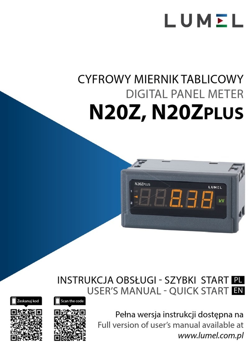
Lumel N32O User manual

N32O User's manual 1
DIGITAL PANEL METER
N32O
SERVICE MANUAL

N32O User's manual 2
Contents
1 Application.......................................................................................................................................3
2 Meter set...........................................................................................................................................5
3 Basic requirements, operational safety.............................................................................................5
4 Installation........................................................................................................................................6
4.1 Installation method...................................................................................................................6
4.2 xternal connection diagram....................................................................................................7
5 Service............................................................................................................................................10
5.1 Description of the frontal plate...............................................................................................10
5.2 Buttons' functions...................................................................................................................12
5.3 Programming meter parameters..............................................................................................13
5.3.1 How to change quantity of a selected parameter............................................................16
5.3.2 Programmable meter parameters, default parameters.....................................................16
5.4 Meter functions.......................................................................................................................23
5.4.1 Measurement...................................................................................................................23
5.4.1.1 Fast changing pulses counter...................................................................................26
5.4.1.2 Slow changing pulses counter.................................................................................28
5.4.1.3 Period measurement................................................................................................29
5.4.1.4 Frequency measurement..........................................................................................30
5.4.1.5 Rotation speed measurement...................................................................................32
5.4.1.6 ncoder (only the main input).................................................................................33
5.4.1.7 Pulse counter with pulse speed measurement (main input only)............................35
5.4.1.8 Working time measurement.....................................................................................38
5.4.1.9 Time measurement..................................................................................................39
5.4.1.10 Additional counters I3 and I4................................................................................39
5.4.1.11 Averaging the measuring quantities.......................................................................39
5.4.1.12 Minimum and maximum measuring values..........................................................40
5.4.1.13 Mathematical functions.........................................................................................40
5.4.1.14 Individual characteristic........................................................................................41
5.4.2 Analog output..................................................................................................................42
5.4.3 Alarm outputs..................................................................................................................43
5.5 RS-485 interface.....................................................................................................................45
5.5.1 Connection......................................................................................................................45
5.5.2 Description of the MODBUS protocol implementation.................................................46
5.5.3 Implemented functions of MODBUS protocol...............................................................46
5.5.4 Map of the registers.........................................................................................................47
5.5.4.1 Registers 4000 – 4079.............................................................................................47
5.5.4.2 Registers 4200 – 4257.............................................................................................54
5.5.4.3 Registers 7500 – 7521 and 7000 – 7043.................................................................56
5.5.4.4 Registers 7600 – 7744 and 7200 – 7489.................................................................57
6 rror codes......................................................................................................................................62
7 Technical data.................................................................................................................................63
8 Ordering code.................................................................................................................................67

N32O User's manual 3
1 Application
The N32O meter is a digital panel meter adapted to be fixed to the panel. The N32O
meters are designed to measure the number of pulses, period, frequency, rotational
speed, number of pulses and their frequency, working time, position support for an
incremental encoder) or any other value that is a derivative of the mentioned parameters.
The N32O meters, thanks to many configuration options, can be used as the media
consumption counters with an indication of a real-time consumption dynamics. Two
measuring channels allow to save an installation space and the costs of the measuring
equipment. The universal inputs with filter functions support the majority of available
sensors with NPN and PNP outputs.
Additionally, the meter supports the programmable alarms with the delay activation and
deactivation function as well as a memory of the alarm event. The functionality of the
meter is complemented by a programmable analog output - RS-485 interface.
The user interface consists four buttons and the high contrast LCD display with backlight.
Thanks to the two-line display, it is possible to set the selected unit, display simultaneously
two measuring values, the measuring value and the current time, as well as a clear and
user friendly menu with simultaneously visible the parameter name and its value.
Features of the N32 meter:
•Wide range of configuration options for measuring pulse signals.
•Possibility of simultaneous measurement in two channels.
•Additional inputs controlling the counters with the possibility to configure their
operation. The additional inputs can also be used as the counters which can be
accessed via the RS-485 interface.
•Compatible with NPN or PNP sensors.
•Additional supply output +24 V to supply the sensors.
•Integrated configurable signal filtering functions which can be disabled. For
example, it is possible, thanks to the filters, to configure the counter to count the
number of elements with holes that may interfere the counting process possibility
of multiple counting for a single element).
•High sampling frequency of the measuring signals.
•Incremental encoder support.
•Dedicated settings for counting slowly changing pulses with the elimination of
interferences, e.g. the pulses from various types of contacts, buttons, switches, etc.

N32O User's manual 4
•Integrated mathematical functions - individual for each channel.
•Two individual characteristics enabling the conversion of the main measuring value
in a given channel according to the programmed characteristic.
•High contrast LCD display with built-in backlight.
•Two-line display.
•Possibility to select the unit of the measuring displayed) value.
•Possibility to simultaneously display two selected measuring quantities or a
measuring quantity and e.g. a unit or time.
•Programmable displayed precision with automatic setting of a decimal point.
•Possibility to program the measuring range narrowing) for the selected displayed
value.
•Additional measurement of minimum and maximum values during the moving
window, with the possibility of programming one of these values to be displayed as
the main one.
•Programmable alarms with the functions of programmable delays of alarm
activation and deactivation, triggered by a specific controlling value. Up to 4 relays,
including up to 3 relays with a switching contact. Possibility to configure each of the
alarms to work in a selected mode and to react to any measuring quantity including
the current time.
•Possibility to control the alarm outputs relay) via the RS-485 interface.
•Programmable standard analog outputs enabling the retransmission of a selected
measuring quantity or a selected parameter. Freely programmable output type and
conversion range.
•Built-in by default RS-485 interface with MODBUS RTU protocol support.
•Built-in real-time clock with a built-in automatic change of DST and inversely. The
clock can be a parameter which controls the alarms and the value of the analog
output signal.
•Possibility to password protect the settings against unauthorized modification.
•Monitoring of set parameters.
•averaging algorithm in a specified time using standard averaging determining the
number of measurements to be averaged) and averaging based on the moving
window algorithm with a given averaging time.
•Signaling of alarm operation by highlighting the number of the active alarm.

N32O User's manual 5
•Registration of minimum and maximum measuring values.
•Galvanic separation of the connections: alarm, measurement, analog outputs,
auxiliary supply outputs, RS-485 interface and supplying input.
•Protection degree from the front IP65.
•Meter overall dimensions 96 x 48 x 100 with the terminals).
•The casing is made of a self-extinguishing plastics.
•Wide range of supply voltages.
The view of the N32O meter is shown in Fig. 1.
2 Meter set
The meter set includes:
•Meter N32O – 1 pc
•User's manual – 1 pc
•Clamps to fix in the panel – 4 pcs
•Seal – 1 pc
3 Basic requirements, operational safety
In terms of a user safety, the N32O meter meets the requirements of the EN61010-1
standard for the devices intended for use in facilities compliant with the third category of
installations.
Comments concerning safety
•Assembly and installation of the electrical connections should conducted only by a
person authorised and certificated to perform assembly of electric devices.
Fig. 1: View of the N32O meter.

N32O User's manual 6
•Always check the connections before turning the meter on.
•The meter is designed to installation and usage in the industrial electromagnetic
environment.
•A switch or a circuit-breaker should be installed in the building or facility. The switch
should be located near the device, easily accessible by the operator and suitably
marked.
•Removal of the meter electronics during the warranty period voids the warranty.
4 Installation
4.1 Installation method
The N32O meters are designed to be mounted in a panel. Prior to installation a 92+0.6 x
45+0.6 mm slot must be made in the panel. The maximum thickness of the panel material
cannot exceed 6 mm. The meter should be mounted from the front of the panel with
disconnected meter connection strips.
Before inserting the meter into the panel check the correct position of the meter seal and
make sure that the edges of the panel are not sharp what could damage the seal. After
inserting the meter into the slot, mount it with the mounting brackets provided in the meter
set Fig. 2).
Electrical connections of the meter should be made with the wires with the cross-section
up to 2.5 mm2 and 1.5 mm2 for the input circuits. Detachable sockets with the plugs of
5.08 mm pitch can be used for the connections and 3.81 mm for the input circuits.
The external dimensions of the meter are shown in Fig. 3.
Fig. 2: Meter fixing.

N32O User's manual 7
4.2 E ternal connection diagram
The N32O meter has three detachable terminal strips to connect the wires of a cross-
section up to 2.5 mm2 and 1.5 mm2 for the input circuits. The view of the meter from the
connectors' side is shown in Fig. 5. The upper terminal strip is optional and depends on
the accessories of the meter.
The circuits of successive groups of the terminals are separated from each other, as
shown in Fig. 4.
Note: Unused terminals of the terminal strips (NC) must not be connected to any signals.
Fig. 3: Meter overall dimensions.

N32O User's manual 8
Detailed description of the signals is shown in the table below, and the connection of the
measuring signals is shown in Fig. 6.
Terminal Function Description
C, 1A,
1B, I2, I3,
I4
Binary Measuring)
inputs
Binary Measuring) inputs for connecting the measuring
signals:
•C – common terminal of measuring signals. The
terminal should be connected to the power supply
ground in the systems with PNP sensors. In the
systems with NPN sensors, the terminal should be
connected to the sensors supply terminal.
•I1A and I1B – main measuring input.
•I2 – additional measuring input.
•I3, I4 – control inputs - inputs functions are

N32O User's manual 9
programmed.
Examples of the connections are shown in Fig. 6.
9, 10, 11 RS-485 RS-485 interface signals
12, 13 Alarm 1 Alarm output 1, which is NO relay contact.
15, 16 Power supply Meter power supply connection. Range of supply voltages
supported by the meter depends on the ordering code. It
is required to check if the rated range of the meter
corresponds to the installation to which the meter will be
connected before installing the meter.
20...28 Alarms 2, 3, 4
optional)
The alarm outputs 2, 3 and 4 use a relay with a switching
contact.
30...34 Analog output Analog output. The output must be properly connected
according to the type of output selected in the
configuration voltage or current): the terminals 30 and 31
for the current output or the terminals 32 and 33 for the
voltage output. It is not possible to use the voltage and
current outputs at the same time - the correct value in
accordance with the configuration, will be available only
for the selected output type.
35, 36 Binary output Open collector binary output for future applications. The
output should be left unconnected.
8, 14, 29 NC Unused terminals. Should be left unconnected.
The example of input signal connections to connect the sensors with PNP output Fig. 6a)
and NPN output Fig. 6b) is shown below.
In the example shown above, the sensor is supplied from the auxiliary power supply
output. Fig. 7 below shows an example of connecting an incremental encoder with PNP
outputs supplied from the auxiliary power supply output Fig. 7a) and a system where the
encoder is supplied from an external power supply Fig. 7b). In the second circuit, an
additional connected button is used to reset the pulse counter position).
Fig. : Connection of the N32O meter.

N32O User's manual 10
5 Service
The N32 meter user interface includes an LCD display and the buttons which enable to
display the measuring value, a full configuration and setting of the meter or modification of
the parameters.
After turning the meter on the display shows the name of the meter and the software
version. If there is no error during meter initialization process, the meter will switch to
displaying the measuring value. If during the initialization any irregularities or deviations
are detected, than a message with information about a detected error will be displayed
see point 6 - Error codes).
5.1 Description of the frontal plate
View of the front panel of the meter is shown in Fig. 8. The LCD display with backlight and
4 buttons are on the front panel. The description of the display fields is shown below. The
button functions are shown in the section 5.2.
Designation Description
L1 The upper main) line of the display has 6 characters used to display a
measuring value or a parameter value during the meter configuration.
L2 The lower auxiliary) line of the display has 5 characters used to display a
measuring value, not converted by the individual characteristic or,
Fig. 8: Front panel of the meter.
Fig. 7: Example of connecting an incremental encoder with PNP outputs.

N32O User's manual 11
according to configuration, a unit or current time.
Z1 Measuring value averaging indicator. Illuminated averaging indicator
informs that the set measuring value averaging period has not elapsed yet.
I3 State of auxiliary input I3.
I4 State of auxiliary input I4.
ALI Alarm status field. This field contains the indicator informing about the
alarm status. Illuminated alarm indicator means that an alarm event is in
progress and the relay corresponding to the alarm is activated. Flashing
symbol means that the alarm state is saved if the alarm memory is
activated).
STP Stop counting indicator lamps counter STOP from the input 1 or the input
2).
B1...B4 Meter operation buttons. The description of the button functions and their
various combinations are shown in section 5.2.
The lower line of the display can be configured to display the unit or a selected measuring
value including time). The available units and the corresponding MODBUS register 4025
values are shown in the table below.
Value in the
register 4007
setting)
Unit Value in the
register 4007
setting)
Unit Value in the
register 4007
setting)
Unit
0 ----- 20 kvarh 40 h
1 mV 21 Mvarh 41 m3
2 V 22 VAh 42 rpm
3 kV 23 kVAh 43 pcs
4 mA 24 MVAh 44 pulses
5 A 25 Hz 45 rps
6 kA 26 kHz 46 m/s
7 W 27 47 l/s
8 kW 28 k48 rpm
9 MW 29 ºC 49 m/min
10 var 30 ºF 50 l/min
11 kvar 31 K 51 pcs/h
12 Mvar 32 % 52 m/h
13 VA 33 %rh 53 km/h
14 kVA 34 pH 54 m3/h
15 MVA 35 kg 55 kg/h
16 Wh 36 bar 56 l/h

N32O User's manual 12
17 kWh 37 m
18 MWh 38 l
19 varh 39 s
5.2 Buttons' functions
Cancel button:
•Exiting the menu and exit to the main screen.
•Exiting a lower level of the menu and return to a higher level.
•Canceling changing the set value when editing the parameter value)
Digit change button:
•Navigating the menu - decreasing the items of the menu.
•Decreasing the controlled quantity while editing a parameter and
setting selection from the list of settings, e.g. alarm type.
•Changing the controlled digit when setting numerical parameters.
•Pressing the button during a normal operation displays a minimum
value for 2 seconds, then the display returns to displaying a measuring
value.
Increase value button:
•Navigating the menu - increasing the items of the menu.
•Increasing the value of the selected parameter or increasing the value
of a digit when changing the numerical value.
•Pressing the button during a normal operation displays a maximum
value for 2 seconds, then the display returns to displaying a measuring
value.
Confirm button:
•Entering the programming mode holding down the button for at least 3
seconds).
•Navigating the menu - entering the parameter value editing mode or
entering the selected lower level of the menu.
•Accepting the changed parameter value.
•Viewing the measuring values in the preview mode.
Deleting minimum value. DELMIN message is displayed after deleting. To avoid
accidentally exit the menu in the preview mode, it is recommended to press first
the button , and then the button and holding them until
DELMIN message is displayed.
Deleting maximum value. DELMAX message is displayed after deleting. To
avoid accidentally exit the menu in the preview mode, it is recommended to

N32O User's manual 13
press first the button , and then the button and holding them
until DELMIN message is displayed.
Deleting alarm memory - hold down the buttons for 3 seconds. ClrAL message
will be displayed after deleting alarm memory.
STOP – Pressing the buttons combination will stop the active counters,
provided that the permission to control the counter using the meter buttons is
enabled in the input configuration bCtrl setting). The buttons operation applies
only to the inputs working in the counter mode.
START – Pressing the buttons combination will start the counters, provided that
the permission to control the counter using the meter buttons is enabled in the
input configuration bCtrl setting). The buttons operation applies only to the
inputs working in the counter mode.
RESET – Pressing the buttons combination will reset set) the counters,
provided that the permission to control the counter using the meter buttons is
enabled in the input configuration bCtrl setting). The buttons operation applies
only to the inputs working in the counter mode.
All the events of deleting of saved minimum, maximum values and alarm activation
memory are indicated by the meter by displaying an appropriate message.
5.3 Programming meter parameters
Programming meter parameters is possible via the RS485 interface and by direct edition of
the parameters using the buttons and the meter display.
Direct programming process is easy thanks to meter menu, which includes the settings
grouped into sections with all parameters related to a given functionality, e.g. all
parameters of the serial interface are grouped in the menu .
Pressing and holding the confirm button for at least 3 seconds allows to switch from a
normal operation to meter menu . If access to change the parameters is password
protected, the user will be requested to enter the access password before entering the
menu. Entering an incorrect password will allow to enter the menu but it will be not
possible to change the parameters - parameters monitoring mode. Entering a correct
password will allow to move to a programming matrix, the menu after entering the
programming mode is shown below.
Fig. 9: View of meter menu.

N32O User's manual 14
While navigating the meter main menu with the groups of the parameters, the upper line of
the display shows the name of the group and the lower line continuously displays the word
MENU. After entering the group of the parameters after pressing the confirm button), the
upper line displays the value of a given setting and the lower line shows the name of the
parameter which value is displayed in the upper line. Sample view of the selection of the
measured input signal type is shown in Fig. 9.
The buttons allow to navigate the menu of the meter. After selecting the
group of the parameters which configuration is to be changed, press the confirm button to
move to the parameters of the group. The parameter which value is to be modified is
selected the same way as the selection of the group. To cancel the parameter change,
press the cancel button to exit the parameter changing mode or the parameter
group. The meter will automatically exit the programming mode and return to displaying
the measuring value if no button is pressed for 30 seconds during programming. The
programming matrix is shown below.
Selection of
measuring quantities
- input type.
Selection of a
rescaling by
constant method.
Constant rescaling
the measuring value
- pulsing number per
a single count
revolution).
The value to or from
which is a counting
for counting down).
Filter - minimum
duration of the low
level on the input.
Filter - minimum
duration of the high
level on the input.
Permission to use
the meter buttons to
operate the counter
Start, Stop, Reset).
Standard averaging -
time of a single
measurement as a
multiple of 100 ms.
Moving window
method averaging -
number of the
measurements to be
averaged window
width).
Mathematical
function selection
based on which the
measuring value
should be converted.
The parameter
available only for
INP 1.
Converter of the
additional measuring
value frequency)
during the
measurement in the
CntFL mode - time
period selection.
Fig. 10: View of menu when setting a parameter.
Parameter
which can be configured
Current value
of a setting

N32O User's manual 15
The function of the
additional input no.
3.
Filter - minimum
duration of the low
level on the input no.
3.
Filter - minimum
duration of the high
level on the input no.
3.
The function of the
additional input no.
4.
Filter - minimum
duration of the low
level on the input no.
4.
Filter - minimum
duration of the high
level on the input no.
4.
Enabling or disabling
the individual
characteristic.
Number of points of
the individual
characteristic.
Measuring value -
point no.1.
Expected value for
the measuring value
X1.
Measuring value -
point no.2.
Expected value for
the measuring value
X2.
... ...
Measuring value -
point no.32.
Expected value for
the measuring value
X32.
Selection of main
displayed value.
Minimum value on
the display. For
values lower than
this value, a lower
overrun message is
displayed.
Maximum value on
the display. For
values higher than
this value, an upper
overrun message is
displayed.
Resolution - position
of the decimal point.
Function of a lower
line of the display -
selection of a
quantity displayed in
the lower line.
Selection of quantity
controlling the alarm
state.
Selection of alarm
type.
Alarm state change
lower threshold.
Alarm state change
upper threshold.
Alarm activation
delay.
Alarm deactivation
delay.
Active alarm
memory.
Meter network
address.
Transmission frame
type - data format.
Baud rate.
Selection of the type
of analog output
used.
Selection of value
controlling the
analog output.
Value of the
controlling quantity
for which the output
will have a minimum
value, in accordance
with the selected
output type.
Value of the
controlling quantity
for which the output
will have a rated
value, in accordance
with the selected
output type.
Value on the analog
output in case of
manual control or an
error on the
measuring input.
Current time
according to the
internal clock.
Current date
according to the
internal clock.
Automatic change of
DST and inversely
Password to protect
against settings
modification.
Restore default
settings

N32O User's manual 16
5.3.1 How to change quantity of a selected parameter
To increase the value of the selected parameter, press the button . Pressing the
button will increases the currently set digit by 1 and after reaching the value 9, pressing
the button will set the value 0. After setting the required value of a digit, move to the next
digit by pressing the button . After setting the required parameter value, press the
confirm button to accept the entered value or the cancel button to cancel
the parameter change and return to the previous value of the parameter. It is possible to
change a sign of the entered value during setting the last digit most significant).
There are three steps to change the floating point values. The first step is to set the digits
and a sign in accordance with the algorithm described above. The second step is set the
position of the decimal point after pressing the confirm button. The buttons
are used to set the position of the decimal point. After setting the decimal point position as
required, press the confirm button to move to the third step - setting the multiplier of kilo,
mega or no multiplier. Symbol of the multiplier value is shown on the left side of the
display.
Entering an incorrect value of a given parameter causes that the new value is not
accepted and the parameter will automatically have the previous value.
To change the parameters other than numerical select the appropriate setting from the
parameter list using the buttons . After selecting the appropriate setting,
press the confirm button to use the setting or the cancel button to return to
the previous value and exit the parameter change mode.
5.3.2 Programmable meter parameters, default parameters
The N32O meters have a number of programmable parameters, which enable the meter to
be adapted to the requirements of application. The parameters grouped according to the
menu are shown in the tables below.
Table
- main input configuration (terminals I A and I B)
- additional input configuration (terminal I2)
Parameter
symbol Description Range of changes
Input mode selection - selection of the
measuring quantity
Default: Cnt SL
CntF – Bidirectional fast pulses counter. Filter time settings in
microseconds.
CNt SL – Bidirectional slow pulses counter. Filter time
settings in milliseconds.
PERIOD – Period measurement. Additional frequency
measurement.
FRE – Frequency measurement. Additional period
measurement.

N32O User's manual 17
tACHO – Rotation speed measurement. Additional frequency
measurement.
ENC* – Counter working with the encoder.
CNtFL* – Pulse counter with frequency measurement. The
mode dedicated for the meters, it is possible to determine the
flow rate in addition to counting. For example, the meter
works with a flow meter, counts the pulses from the flow
meter and converts the flow rate.
W tIME – Bidirectional working time counter.
tIMER – Bidirectional timer expressed in seconds with a
resolution of 1 millisecond.
tIME* – Real-time clock
* - only available for the first channel INP 1
Selection of the basic method of measuring
quantity conversion. Multiplication or division
by the value defined by CONSt parameter.
Default: DIV
DIV – division by a constant.
MUL – multiplication by a constant.
Constant rescaling the measuring value. The
measuring value is multiplied or divided by this
value depending on SCAL setting. Entering a
negative value in the counter modes causes
the counter to count down.
Default: 1
-99999...999999
For counting up, the setting value determines
the value up to which the counter will be
counting. The counter is automatically reset
and counting starts from zero after reaching
this value.
For counting down, the setting value
determines the initial value of the counter after
a reset. During counting down, the counter will
automatically return to the value set in CAUtO
when the counter reaches the value 0.
The value determines the encoder counter
range for the encoder mode. The encoder
counts to CAUTO value and then resets for the
clockwise direction of the encoder rotation. The
counter counts down to 0 and then sets CAUtO
value for the counterclockwise direction of the
encoder rotation.
Default: 999999
-99999...999999
Minimum duration of a low level on meter input
before it is considered as the low level. Pulses
with a shorter low level duration are ignored.
The value is expressed in microseconds for
CntF mode. And the setting is expressed in
milliseconds for CNT SL mode.
Default: 0
0…60000
Note: Entering a duration time below 50 ms disables the low
level filtering function.
Minimum duration of a high level on meter
input before it is considered as the high level.
Pulses with a shorter low level duration are
ignored.
The value is expressed in microseconds for
CntF mode. And the setting is expressed in
milliseconds for CNT SL mode.
Default: 0
0…60000
Note: Entering a duration time below 50 ms disables the high
level filtering function.
Permission to control the counter using the
meter buttons.
Default: ON
ON – Control enabled. The following actions can be
performed using the meter buttons: Start, Stop and Reset of
the counter.
OFF – Control disabled.
Note: The setting only applies to the inputs set as the counter
input.
Measurement time. The setting determines the
period of measurement gating) during the
frequency or period measurements. It also
determines the maximum duration time of the
measurement and limits the measurement of
low frequencies. The period of the measuring
signal must be shorter than the measurement
time.
The setting defines for the counter type inputs
Default: 10
1...600 – The value is expressed as a multiple of 100 ms.
For example, the setting 10 sets the measurement time to 1
second and limits the frequency period) measurement to the
waveforms higher than 1 Hz.

N32O User's manual 18
only data acquisition period for the averaging
algorithm using the moving window method.
Number of the item for moving window method
averaging. Each item is a measurement taken
in SAVG time.
Note: The averaging using the moving window
method is disabled for the counter types.
However, the minimum and maximum value in
the time period set by MAVG setting is saved.
Default: OFF
Mathematical function selection which should
be applied for the measuring value. The
mathematical function is applied before the
value is converted by the individual
characteristic.
Note: The setting has no effect in W tIME and
tIME modes.
Default: NONE
NONE – no additional mathematical operations.
Sqr – measuring value is squared.
Sqrt – square root of the measuring value.
Inv – reciprocal of the measuring value.
InvSq – reciprocal of the measuring value is squared.
InvSt – square root of reciprocal of the measuring value.
The setting applies only to CNtFL mode which
is available only for the input 1, and determines
the period for which the input pulses speed
frequency) is to be converted. For example,
the measuring value would be 600 at 10 pulses
per second and the setting /min.
Default: /SEC
/SEC – conversion of the pulse speed for one second period.
/MIN – conversion of the pulse speed for one minute period.
/HOUR – conversion of the pulses speed for one hour period.
Table 2
Parameter
symbol Description Range of changes
The function of the input no. 3 terminal I3).
Each pulse on this input increases the counter
no. 3, regardless of the function of the input.
The functions assigned to the input refer to the
control of the inputs configured to work in the
counter mode.
Default: NONE
NONE – no function
C1 SS, C2 SS – control of the main input counter modes).
An active signal at the input starts the counter and counting.
The counter is stopped at no signal at the input - the pulses
are not counted. The counter operation is controlled by the
input level.
C1 STA, C2 STA – start the counter. Edge control - input
signal starts the counter.
C1 STP, C2 STP – stop the counter. Edge control - input
signal stops the counter.
C1 RST, C2 RST – input signal resets the counter. The initial
value of the counter after a reset) depends on set counting
direction see the parameter CONSt) .
C2 DIR – change counting direction. During an active signal
the counting direction of the additional input of the counter
I2) is changed.
C12SS – control of the main input and the additional input
counter modes). An active signal at the input starts the
counters and counting the pulses. The counters are stopped
at no signal at the input - the pulses are not counted. The
counters are controlled by the level.
Note: C1 refers to the main input I1) and C2 refers to the
additional input I2).
Minimum duration of a low level on meter input
I3 before it is considered as the low level.
Pulses with a shorter low level duration are
ignored.
The setting is expressed in milliseconds.
Default: 10
0…65535
Minimum duration of a high level on meter
input I3 before it is considered as the high
level. Pulses with a shorter high level duration
are ignored.
The setting is expressed in milliseconds.
Default: 0
The function of the input no. 4 terminal I4). Default: NONE

N32O User's manual 19
The setting range is the same as for IN3 F parameter.
Minimum duration of a low level on meter input
I4 before it is considered as the low level.
Pulses with a shorter low level duration are
ignored.
The setting is expressed in milliseconds.
Default: 10
0…65535
Minimum duration of a high level on meter
input I4 before it is considered as the high
level. Pulses with a shorter high level duration
are ignored.
The setting is expressed in milliseconds.
Default: 10
0…65535
Table 3
- main input individual characteristic configuration (terminals I1A and I1B)
- additional input individual characteristic configuration (terminal I2).
Parameter
symbol Description Range of changes
Enable or disable the individual characteristics.
The OFF setting makes possible to disable the
individual characteristic function.
Default: OFF
OFF – individual characteristic disabled.
ON – individual characteristic enabled.
Number of points of the individual
characteristic.
Default: 2
2…32
The first point of the individual characteristic -
the value measured directly or the value
converted by the mathematical function.
Default: 0
-99999…999999
The first point of the individual characteristic -
expected value for the value X1.
Default: 0
-99999…999999
...
Last possible point of the individual
characteristic.
Default: 31
-99999…999999
Last possible point of the individual
characteristic – expected value for X32.
Default: 31
-99999…999999
Table 4
Parameter
symbol Description Range of changes
Selection of the main value displayed on the
top line of the display.
Default: VAL
VAL – value of the measuring quantity converted by CONSt
parameter. It is a measuring value without an individual
characteristic, without conversion by the mathematical
functions and without averaging using the moving window
method.
VALIND – averaged value of the measuring quantity,
converted by the mathematical functions and converted by
the individual characteristic.
Note: Averaging is not active for the counter type
measurement modes.
VALEXt – Value additionally measured is converted only by
CONSt parameter e.g. a frequency during the period

N32O User's manual 20
measurement).
MIN MW – minimum value registered during the averaging
period of the moving window method during the window)
MAX MW – maximum value registered during the averaging
period of the moving window method during the window)
Note: The window length can be programed MAVG
parameter).
Display narrowing lower threshold. If the value
to be displayed is below the threshold, the
lower limit symbol is displayed
.
Default: -99999
-99999…999999
Display narrowing upper threshold. If the value
to be displayed is above the threshold, the
upper limit symbol is displayed
.
Default: -99999
-99999…999999
Resolution, display format as the position of
the decimal point.
Default: 0000.00
000000
00000.0
0000.00
000.000
00.0000
0.00000
AUTO – automatic position of the decimal point for maximum
possible resolution.
Selection of the parameter displayed in the
lower line of the display.
Default: UNIt
UNIt – unit
VAL 1 – measuring value on the main input I1) without
conversion and without averaging, calculated only by CONSt
parameter.
IND 1 – measuring value on the main input converted by the
mathematical functions, individual characteristics and
averaged.
Note: Averaging is not active for the counter type
measurement modes.
EXt 1 – value additionally measured on the main input e.g. a
frequency during the period measurement).
VAL 2 – measuring value on the additional input I2) without
conversion and without averaging, calculated only by CONSt
parameter.
IND 2 – measuring value on the additional input converted by
the mathematical functions, individual characteristics and
averaged.
Note: Averaging is not active for the counter type
measurement modes.
EXt 2 – value additionally measured on the additional input
e.g. a frequency during the period measurement).
clock – current time.
INPUtS – displaying the status of all inputs. The character 0
is displayed for the given input, if the input is inactive, or the
character 1, if the input is active.
Note: The averaging period is defined by MAVG setting.
Other manuals for N32O
1
Table of contents
Other Lumel Measuring Instrument manuals