Lumel NA6PLUS User manual

METER WITH A MULTICOLOURED
BARGRAPH
NA6PLUS
USER’S MANUAL

NA6Plus-09 User’s Manual 2___________________________________
Contents
1. APPLICATION..................................................................................................................3
2. S4AI SET..........................................................................................................................4
3. BASIC REQUIREMENTS, OPERATIONAL SAFETY.......................................................4
4. INSTALLATION................................................................................................................5
4.1. Installation.................................................................................................................5
4.2. External connections diagram...................................................................................6
5. Operation..........................................................................................................................8
5.1 Changing meter parameters from the keyboard.......................................................10
6. RS-485 Interface............................................................................................................23
6.1. Serial interface connection method.........................................................................23
6.2 MODBUS protocol....................................................................................................23
6.3 Description of the MODBUS protocol functions........................................................24
6.4 Map of NA6Plus meter registers...............................................................................25
6.5 Registers for recording and reading.........................................................................26
6.6 Read-only registers..................................................................................................33
7. Meter configuration with E-Con software........................................................................35
8. METER PROGRAMMING EXAMPLES..........................................................................35
9. BEFORE YOU NOTIFY A DEFECT................................................................................37
10. SOFTWARE UPDATE..................................................................................................38
11. TECHNICAL DATA........................................................................................................39
12. ORDERING CODES....................................................................................................42

NA6Plus-09 User’s Manual 3___________________________________
1. APPLICATION
NA6Plus series meters with a bar graph have a universal input designed to measure temperature,
resistance, voltage from shunts, standard signals, DC voltage and DC current. They can be used in
various industries, such as: food industry, pumping stations and sewage treatment plants, chemical
industry, weather stations, meteorological stations, breweries They are intended for the
visualization of the measured quantity and evaluation of change trends of controlled technological
processes. They can also be used in automation systems where programmed controllers are
applied.
NA6Plus meters have, depending on the version, one or two continuous outputs (voltage or
current), 4 relay outputs or 8 open collector (OC) type outputs, as well as an RS-485 interface. The
meters are programmable via the keyboard and via RS-485.
NA6Plus meters performs the following functions:
measurement of the input quantity and displaying it on the display and the bar graph,
recalculating of the input signal into indication on the base of the individual multipoint
characteristics,
arithmetic on the channels: addition, subtraction, multiplication, division, power and
square root;
programming of colours and bar graph resolutions,
signalling of exceeding the set alarm values;
recording of the measured signal in programmed time intervals,
storage of maximum and minimum values,
programming of the measurement averaging time,
programming of the indication resolution,
deadlock of the parameter introduction by means of a password,
conversion of the measured quantity into a voltage or current output signal,
RS-485 interface support in MODBUS RTU protocol.
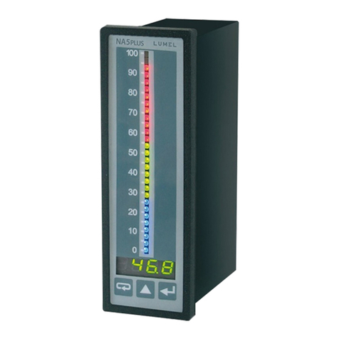
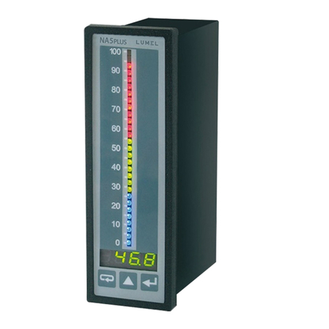
Fig. 1: View of NA6Plus meter.

NA6Plus-09 User’s Manual 4___________________________________
2. S4AI SET
The complete set of NA6Plus meter includes:
•NA6Plus Meter 1 pc
•User’s manual 1 pc
•Signal terminal strip (16 terminals) 2 pcs
•Supply terminal strip (3 terminals) 1 pc
•holders to fix the meter in the panel 2 pcs
3. BASIC REQUIREMENTS, OPERATIONAL SAFETY
Meaning of the symbols used in this manual:
Warning!
Warning of potentially dangerous situations. It is especially important to read
and understand these instructions before connecting the device. Failure to
meet the instructions that are marked with this symbol can result in serious
injury of personnel and damage to the device.
Caution!
Generally useful notes. Following these instructions ensures easy operation of
the device. The user must take them into account when the operation of the
device does not meet the user’s expectations.
Possible consequences when these instructions are not followed!
In terms of operational safety, the meter meets the requirements of EN 61010-1.
Safety instructions:
The assembly and the installation of the electrical connections may be carried out only by a
duly qualified electrician.
The person performing the installation is responsible for the safety of the system in which
devices is installed.
Before turning on the module, verify the connections.
Removal of the meter housing during the warranty period voids the warranty. The module
power supply must be turned off and the input circuits disconnected before opening the
housing.
The device is intended for installation and use in industrial electromagnetic environments.
A switch or a circuit-breaker should be installed in the building or facility. It should be
located near the device, easily accessible to the operator, and suitably marked.
In the event of damage, the meter can be repaired only by the service authorized by the
manufacturer.
Before using the repaired meter make sure that it is working properly.
Connection of the meter and/or its usage inconsistently with this manual can reduce the
operational safety of the meter.
NA6Plus-09 User’s Manual 5___________________________________
4. INSTALLATION
4.1. Installation
The NA6Plus meter is designed to be mounted on a panel. For this purpose, a 44.0 x 137.5 mm
hole should be prepared in the panel. The thickness of the material from which the panel was
made should be in the 1.45 mm range.
In the back of the meter housing there are detachable terminal strips, enabling connection of power
supply, input signals, output signals and RS482 interface with wires with a cross-section of up to
2.5 mm2. The dimensions of the meter are shown in Fig. 2.
Fig. 2: Dimensions of the meter

NA6Plus-09 User’s Manual 6___________________________________
4.2. External connections diagram
The connections of the meter are shown in Figure 3. In the event when the meter is powered with
DC voltage, the voltage polarity does not matter.
Fig. 3: Electrical connections of NA6Plus meter
*) optional elements, depending on the meter's version
PE
230V AC
N
-
24 V DC
+
± 600 V
± 40 mA
± 5 A
GND
± 300 mV
R
± 600 V
± 40 mA
± 5 A
GND
± 300 mV
R
GND
RS-485 B
A
+
OUT 2*
-
+
OUT 1
-
GND
OC8
RL4*
OC7
OC6
RL3*
OC5
OC4
RL2*
OC3
OC2
RL1*
OC1
16
15
14
13
12
11
10
9
8
7
6
5
4
3
2
1
19
18
17
20
21
22
23
24
25
26
27
28
29
30
31
32
33
34
35

NA6Plus-09 User’s Manual 7___________________________________
Resistance thermometer in two-
wire system or resistance
measurement
Resistance thermometer in
three-wire system Thermocouple or ± 75 mV,
±300 mV voltage
± 10 V, ± 600 V voltage input ± 40 mA current input ± 5 A current input
Fig. 4: Input signals connection method
8 open collector (OC) outputs 4 relay outputs
Fig. 5: Output signals connection method
depending on the version
Taking into consideration electromagnetic interference it is recommended to use shielded
conductors for the connection of input and output signals. The power supply must be connected by
means of a two-wire conductor with a suitable cross-section ensuring its protection by means of an
installation fusible cut-out, in case of a short-circuit.
The requirements concerning the supply cable are regulated by EN 61010-1 p.6.10 standard.
8 9 10
1 2 3
R
loop 1
loop 2 8 9 10
1 2 3
Loop 1
loop 2
R
9 10
loop 1
loop 2
2 3-
+
Loop 1
loop 2 10 11 12 13
3 4 5 6
GND ± 600 V
loop 1
loop 2 10 11 12 13
3 4 5 6
GND ± 300 mA
loop 1
Loop 2 10 11 12 13
3 4 5 6
GND ± 5 A
GND OC8 OC7 OC6 OC5 OC4 OC3 OC2 OC1
27 28 29 30 31 32 33 34 35
RL4 RL3 RL2 RL1
28 29 30 31 32 33 34 35
23 24 25 26
AN2 AN1
++
--
Contious outputs (voltage/current)
20 21 22
GND B A
interface RS-485 (MODBUS)

NA6Plus-09 User’s Manual 8___________________________________
5. Operation
After connecting external signals and switching on the power supply, the meter displays the type
and current version of the meter program.
After ca 3 seconds, the meter switches automatically to the operating mode in which it carries out
measurements and displays the measured value on the display and the bar graph. Depending on
alarm parameters settings, the resolution and bar graph type, alarm thresholds are also displayed
on the bar graph. The meter blanks automatically insignificant zeros.
Fig. 6: Description of the front panel of the NA6Plus meter
Functions of the keys:
accept key
–entering the programming mode (hold this key for about 3 seconds).
–entering the chosen parameter level,
–entering the parameter value changing mode
–accepting the changed parameter value.
value increase key
–displaying the minimum and maximum values successively for
subsequent measurement channels
–navigating the preview menu or programming matrix
–changing the value of the selected parameter - increasing the value
Display (input 1) accept button
increase value button
resignation button
Bargraf
(input 1)
lower alarm threshold
(input 2)
upper alarm threshold
(input 1)
bargraf (input 2)
Display (input 2)

NA6Plus-09 User’s Manual 9___________________________________
cancel key
–entering the menu of registered results
–entering the parameter preview menu (hold for about 3 seconds)
–exit from the preview menu or programming matrix
–resignation from the parameter change
Pressing and holding the key for about 3 seconds causes entering the programming mode.
The programming mode is secured with the security code.
Pressing and holding the key for about 3 seconds causes entering the menu of the preview
and the menu of recorded values. Navigating the preview menu is done using the key.
In this menu, all programmable parameters of the meter are available for read-out, with the
exception of service parameters. The exit from the preview menu is done by means of the
key.
An overview of the recorded values is possible after pressing the key on the
parameter in the preview menu. The recorded result number is displayed alternately
with the value e.g. /. Navigating the recorded values is done using the key.
Holding this key for longer than about 2 seconds will speed up the browsing. Pressing the
key at any time will display the number of recorded results. The exit from the viewing recorded
values is done by pressing the key.
Rys. 7 The NA6Plus meter operation algorithm
navigating
through the
preview
password
entry mode
seC
3 s
Correct
password
programming
matrix
yes
no
display of the
inscription
err
Matrix
navigation
- entrance to the selected level
- entry to parameter changes
- exit from the programming
matrix
resetting of alarm
outputs
Measurement
3 s
Preview
menu
Displaying the minimum
value
CH1
Displaying the maximum
value
CH1
Displaying the minimum
value
CH2
Displaying the maximum
value
CH2
preview recorded
values
3 s
Navigation
around next
values

NA6Plus-09 User’s Manual 10___________________________________
Displaying the following symbols and inscriptions on the display means:
err incorrectly entered security code
**** upper measuring range exceeded or no sensor
____ lower measuring range exceeded or no sensora
errC error of the conductor resistance compensation. Conductor not connected or
damaged
5.1 Changing meter parameters from the keyboard
Pressing the key for approx. 3 s causes the display of the message alternately with the
factory-set value of 0. Entering the correct code results in entering the programming mode. Figure
8 shows the transition matrix in the programming mode. The key allows for moving around
the main parameters groups, e.g.: Ch1, Ch2, bAr1, bAr2, AL1, AL2, etc. Pressing the key
on the given level, causes the entry into parameters of this level. Moving around a given level
takes place by means of the key . To change the value, use the . To cancel the
parameter change, press the key . The same key is used to exit the selected level and
programming matrix to the measurement.
The transitions matrix in the programming mode is shown in Figure 9.
During operation of the meter in the programming mode, the measurement result is displayed on
the bar graph, except for selecting the display test function.
Examples of changing the value of the selected parameter (parameter – symbol)
Example of changing the value of the selected parameter with a fixed decimal point
(numeric parameter)
0000
000.0
00.00
0.000
Auto
On
OFF
00!0 00!5 00!5 00!5 !5
blanking off
meaningless zeros
Changing of the
blinking position
Changing of the blinking
position
Changing of the blinking
positioni
Changing of the
blinking position

NA6Plus-09 User’s Manual 11___________________________________
Example of changing the value of the selected parameter with a variable decimal point
(numeric parameter)
Fig. 8 Examples of changes in parameter values
00!0
00!5 00!5 00!5 00!5 !500
Changing of the
blinking comma
Changing of the
blinking position
Changing of the
blinking position
Changing of the
blinking position
Changing of the
blinking position
0-9, -, -1
automatic adjustment
of the decimal point

NA6A-07 User’s Manual 12
Main
menu Parameters of the selected level
…
Input
type
temper
ature
unit
°C/F
lower
value of
the
input
range
upper
value of
the
input
range
mathe
matical
function
s
type of
compen
sation
decimal
point
measur
ement
time
individu
al input
charact
eristics
number
of
points
of
Individual
charact
eristics
parame
ter 1
of
individual
charact
eristics
parame
ter 1
of
individual
charact
eristics
...
number
of
points
determi
ned by
the PtS
value
(max.
21)
parame
ter 21
of
individual
charact
eristics
parame
ter 21
of
individual
charact
eristics
…
bar
graph
type
bar
graph
colour
lower
threshol
d of bar
graph
indicati
on
upper
threshol
d of bar
graph
indicati
on
...
input
channel
lower
alarm
threshol
d
upper
alarm
threshol
d
alarm
type
alarm
delay
holding
up the
alarm
colour
of the
lower
alarm
marker
colour
of the
upper
alarm
marker
Value of
change
in the
measur
ed
signal
time of
change
in the
measur
ed
signal

NA6A-07 User’s Manual 13
...
input
channel
output
individulal
charact
eristics
parame
ter of
individual
charact
eristics
parame
ter of
individual
charact
eristics
parame
ter of
individual
charact
eristics
parame
ter of
individual
charact
eristics
baud
rate
method
of
transmi
ssion
device
address
display
and bar
graph
test
time
setting
setting
the
settings
access
code
erasing
the
minimum
values
erasing
the
maximum
values
factory
settings
recording
channel
1
recording
start
channel
1
recording
date
channel
1
recording
interval
channel
2
recording
start
channel
2
recording
date
channel
2
recording
interval
Figure 9 Transition matrix in programming mode.

NA6Plus-09 14 User’s Manual
Programmable parameters of the NA6Plus meter
Symbol on
the
display
Parameter description Scope of changes
Input parameters
Input type resistance thermometers:
pt1 – Pt100
pt5 – Pt500
pt10 – Pt1000
thermocouples:
zte- – J thermocouple
te-h – K thermocouple
te-n – N thermocouple
te-e – E thermocouple
te-r – R thermocouple
te-s – S thermocouple
te-t – T thermocouple
- resistance up to 10 k
75mU - voltage up to ± 75 mV
300m - voltage up to ± 300 mV
10U - voltage up to ± 10 V
600U - voltage up to ± 600 V
40mA - current up to ± 40 mA
5a - current up to ± 5 A
Unit of thermometric quantity
Possibility to select the unit in which the
temperature measurement result is
displayed (°C/°F)
: Celsius degrees
.– Fahrenheita degrees
Lower value of the input range
Setting the LoIn and HiIn parameters gives
the possibility of narrowing the
measurement range
Possible settings: -1999...9999
At the input signal <LoIn the meter will display
the lower range exceeding.
The LoIn <HiIn condition must be met.
The parameter does not take into account the
individual characteristics, it works on the
measured signal only.
Upper value of the input range Possible settings: -1999...9999
At the input signal <HiIn the meter will display
the upper range exceeding.
The LoIn < HiIn condition must be met.
The parameter does not take into account the
individual characteristics, it works on the
measured signal only.
Mathematical functions performed on
channels
- mathematical functions are turned off
– exponentiation (result)2
– square root
√
result
COPY – result copying
result1result2for channel 1
result2result1for channel 2
when the channels measure thermometric
values, selecting different temperature units
(°C/°F) on both channels and activating the copy
function will convert the values according to the
unit selected for the appropriate channel

NA6Plus-09 15 User’s Manual
– adding result1+ result2
– subtraction
result1result1– result2for channel 1
result2result2– result1for channel 2
– multiplication result1
⋅
result2
– division
result1result1: result2for channel 1
rresult2result2: result1for channel 2
Type of compensation for changes in
the sensor working conditions
- in the case of a resistance thermometer
and resistance measurement, it applies to
the compensation of changes in the
resistance of wires connecting the sensor
with the meter
- in the case of a thermocouple, it applies
to the compensation of temperature
changes of the reference joints
Avto - automatic compensation (in the case of
resistance thermometers and resistance
measurement it requires a three-wire line)
0,0...60,0 °C – reference temperature value for
thermocouples
0,0...40,0 Ω– resistance of two wires for
resistance thermometers and resistance
measurements
Entering values outside the manual
compensation range (e.g. 70.0) will cause
switching on automatic compensation.
Decimal point setting
The setting works both with the individual
characteristics switched off and switched
on. Entering a decimal point which makes
displaying four characters on the display
impossible results in displaying the lower
or upper exceeding.
Possible settings:
0000
00)0
0)00
)000
avto - automatic selection of decimal point
Averaging time of the measurement 0,0...999.9 s
Entering 0 causes the measurement to be
turned off and the meter to stop working. The
meter displays the time in this state. The bar
graph is blank.
Turning off or on individual
characteristics
– characteristics on
– characteristics off
Number of points of Individual
characteristics
Determining the number of points for a
multi-point individual characteristic.
Possible settings: 2...21
Entering a value smaller than 2 sets the number
of points to the minimum value (2), entering a
value greater than 21 sets the number of points
to the maximum value (21).
...
Parameters of individual characteristics
The number of points used to shape the
individual characteristics is determined by
the PtS parameter.
Based on the coordinates of successive
points given by the user, the meter
determines (from the system of equations)
the individual characteristics coefficients a
and bfor the sections connecting
successive points of the characteristics.
{
dY01=a1
⋅IH01+b1
dY02=a1
⋅IH02+b1
{
dY02=a2
⋅IH02+b2
dY03=a2
⋅IH03+b2
Possible settings: -1999...9999

NA6Plus-09 16 User’s Manual
{
dY20=a20
⋅IH20+b20
dY21=a20
⋅IH21+b20
where:
IH01...IH21 – measured values
dY01...dY21 – expected values
Bargraf parameters /
Bar graph type - one-colour bar graph
– sectional bar graph
– segmented bar graph
- point bar graph
- trend bar graph
Bar graph colour - bar graph off
- red
g- green
g- red + green
Other colours available only in meters with a
seven-colour bar graph
- blue
- red + blue
g- green + blue
g- red + green + blue
Lower threshold of bar graph indication
Parameter for setting the "magnifying
glass" on the bar graph. The value on the
display at which the bar graph is to be
blanked.
Possible settings: -1999...9999
Upper threshold of bar graph indication
Parameter for setting the "magnifying
glass" on the bar graph. The value on the
display at which the bar graph is to be fully
illuminated.
Possible settings: -1999...9999
Alarm parameters ...
Selection of the channel to which the
alarm should react
– channel 1
– channel 2
Lower alarm threshold Possible settings: -1999...9999
Upper alarm threshold Possible settings: -1999...9999
Alarm type – normal on
– normal off
- switched on
- switched off
– manually switched on; until the alarm
type is changed, the alarm output is permanently
switched on
– manually switched off; until the alarm
type is changed, the alarm output is permanently
.
.
.

NA6Plus-09 17 User’s Manual
switched off
– reaction to the slope
Alarm delay
The parameter is defined in seconds.
Defines the time to elapse from the time of
alarm occurence to the time when alarm
output is triggered. The alarm is activated
after averaging the measurement.
The alarm is switched off without delay.
Possible settings: 0,0...999.9 s
Entering 0.0 causes the alarm to be activated
when it occurs.
Maintaining alarm signaling
When the function is switched on, after the
alarm state has disappeared, the alarm
reamins activated (relay contacts or OC
output).
SThe alarm state is active until it is erased
by the combination of and keys.
- alarm output hold up is disabled
- alarm output hold up is enabled
The colour of the lower alarm threshold
marker
- bar graph off
- red
g- green
rg - red + green
Other colours available only in meters with a
seven-colour bar graph
- blue
- red + blue
gb - green + blue
rgb - red + green + blue
The colour of the upper alarm threshold
marker
Value of change in the measured signal
The change value of the signal measured
at the time specified in parameter .
After exceeding the set threshold, the
alarm is activated (relay contacts or OC
output).
Exceeding the threshold tvalue increase in
time is signaled by an intermittent message
of the length of 1s on the display.
ALx- Where x is the alarm number.
Occurs in the case of a measured signal
increase.
ALx_ - Where x is the alarm number.
Occurs when the measured signal
decreases.
When the alarm stops, the message
disappears.
Possible settings: -1999...9999
Entering positive values causes the alarm to be
activated if the rate of change of the measured
signal in the indicated time increases above the
entered value (the alarm reacts to the
speed of the increase of the measured signal)
Entering negative values causes the alarm to be
activated if the rate of change of the measured
signal in the indicated time decreases above the
entered value (the alarm reacts to the
speed of the decrease of the measured signal)
Entering the value 0 deactivates the alarm
function
time of change in the measured signal Possible settings: 0...3600 sec.
Entering the value 0 deactivates the alarm
function

NA6Plus-09 18 User’s Manual
Output patametrs /
Selection of the channel to which the
output should react
– channel 1
– channel 2
Turning off or on individual
characteristics
– characteristics on
– characteristics off With the characteristics
turned off, the meter operates with a maximum
range depending on LoIn and HiIn input range
Parameters of the individual output
characteristics
Based on the coordinates of two points
given by the user, the meter determines
(from the system of equations) the
individual characteristics coefficients aand
b.
{
O_Y1=a⋅d_H1+b
O_Y2=a⋅d_H2+b
where:
d_H1, d_H2 – displayed values
O_Y1, O_Y2 – expected values on the
output
Possible settings: -1999...9999
parameters
RS-485 interface baud rate @4 – 2400 b/s
$8 – 4800 b/s
(6 – 9600 b/s
1(2 – 19200 b/s
5&6 – 57600 b/s
11%2 – 115200 b/s
Transmission method via RS-485
interface
- interface off
– RTU 8N2
– RTU 8E1
– RTU 8O1
– RTU 8N1
Device address for MODBUS protocol Possible settings: 1...247
Service parameters
Display and bar graph test
The test consists in displaying the numbers
1111, 2222, etc. on the displays.
Subsequent points are lit on bar graphs in
the available colours. The test continues
until it is turned off.
– disabling the test
– ebabling the test
After activating, the test will start after exiting the
menu.
Setting the current time
Time format: hh.mm
The clock is reset after a voltage failure
Possible settings: 00.00 … 23.59
Entering the password Possible settings: -1999... 9999
Setting the value to 0 disables the entry
protection for the menu.
Erasing the minimum values – do not erase
– erasing the minimum values
Erasing the maximum values – do not erase
– erasing the maximum values
Factory parameters
Restoring factory parameters of the meter.
– do nothing
– restore factory parameters

NA6Plus-09 19 User’s Manual
recording parameters
Enabling or disabling recording
At the moment recording is enabled, the
meter deletes the previous stored channel
1 and 2 values.
– recording off
– channel 1 recording on
– channel 2 recording on
– noth channel recording
Channel 1 recording start time
Time format: hh.mm.ss
Possible settings: 00.00.00 … 23.59.59
Channel 1 recording start date
Date format: yy.mm.dd
Possible settings: 00.01.01 … 99.12.31
Channel 1 recording interval
Specifies the time segment after which the
result is to be saved.
The minimum interval is 1 second.
Time format: hh.mm.ss
Possible settings: 00.00.01 … 24.00.00
Channel 2 recording start time
Time format: hh.mm.ss
Possible settings: 00.00.00 … 23.59.59
Channel 2 recording start date
Date format: yy.mm.dd
Possible settings: 00.01.01 … 99.12.31
Channel 2 recording interval
Specifies the time segment after which the
result is to be saved.
The minimum interval is 1 second.
Time format: hh.mm.ss
Possible settings: 00.00.01 … 24.00.00
1
0
Output state
Displayed value
1 – output enabled
0 – output disabled
PrL PrH
a)
1
0
PrL PrH
1 – output enabled
0 – output disabled
Displayed value
Output state
b)
c)
1
0
PrL PrH
1 – output enabled
0 – output disabled
Displayed value
Output state
d)
1
0
PrL PrH
1 – output enabled
0 – output disabled
Displayed value
Output state

NA6Plus-09 20 User’s Manual
Fig. 10 Alarm types a, b – normal; c – switched off; d – switched on; e - delt
Caution: H_On alarm is always active, H_OF alarm is always inactive
e)
time
Measured value
0 T 2T 3T … nT T – meter processing time, approx. 0.2 s
n – another measurement
Θ- slope determined by
parameters and
δ
δ
Alarm
disabled
(δ< Θ)
Alarm enabled (δ> Θ)
Θ
D_t
De L t
Table of contents
Other Lumel Measuring Instrument manuals
Popular Measuring Instrument manuals by other brands

Ruskin
Ruskin EFAMS Installation and maintenance manual

DH Instruments
DH Instruments PG7607 - 2008 Operation and maintenance manual

Testec
Testec TT-SI 9101 instruction manual

LOVATO ELECTRIC
LOVATO ELECTRIC DME D110T1 instruction manual

Güralp
Güralp Minimus Technical manual

Trinity
Trinity SLM102 user manual

Hitachi
Hitachi RES670 Commissioning manual

EDAN
EDAN M3A user manual

Bms Bulut Makina
Bms Bulut Makina TKM-459 Operational manual

ATI Technologies
ATI Technologies C12-17 Operation and maintenance manual

Fluidwell
Fluidwell F Series Operation manual

Trace2O
Trace2O METALYSER FIELD PRO HM3000 instruction manual