Lumel N27P User manual

1
RAIL MOUNTED NETWORK METER
N27P
USER’S MANUAL

2

3
Contents
1. APPLICATION.................................................................................. 5
2. METER SET..................................................................................... 6
3. BASIC REQUIREMENTS, SAFETY OF USE.................................. 7
4. INSTALLATION................................................................................ 8
4.1 Mounting method...................................................................... 8
4.2 Connections............................................................................ 10
5. OPERATION ...................................................................................11
5.1 Description of front panel.......................................................11
5.2 Messages after switching the power supply on ...................11
6. MENU............................................................................................. 12
6.1 Display..................................................................................... 12
6.2 Menu structure........................................................................ 15
6.3 Programming the inputs ........................................................ 18
6.4 Reseting counters .................................................................. 20
6.5 Display settings ...................................................................... 21
6.6 Programming the alarms ....................................................... 22
6.7 Programming the outputs...................................................... 29
6.8 Service settings ...................................................................... 31
7. SERIAL INTERFACES................................................................... 33
7.1 RS485 – list of parameters..................................................... 33
7.2 USB – list of parameters ........................................................ 34
7.3 Map of N27P meter registers ................................................. 34
8. ERROR CODES............................................................................. 49

4
9. FIRMWARE UPDATING ................................................................ 50
9.1 Software L1 level update........................................................ 50
9.2 Software L2 level update........................................................ 53
10. TECHICAL SPECIFICATION....................................................... 54
11. ORDERING CODE ....................................................................... 59

5
1. APPLICATION
The N27P is a programmable digital device used to
measure the parameters of single-phase electrical networks.
The meter measures and calculates the following values:
• phase voltage
• 10 minutes’ mean voltage
• current
• active power
• reactive power
• apparent power
• active power factor
• ratio of reactive/active power
• mean active power
• phase shift
• input of active energy
• output of active energy
• input of reactive energy
• output of reactive energy
• apparent energy
• frequency
• 10 seconds’ mean frequency
• time
• maximum and minimum values of:
- phase-to-neutral voltage;
- current;
- active power;
- reactive power;
- apparent power;
- active power factor;
-tangentφ;
- frequency;
- average active power;

6
2. METER SET
The meter set comprises:
- N27P meter ............................. 1 pc
- User Manual............................ 1 pc
- Warranty Card ......................... 1 pc
- CD ........................................... 1 pc
Accessories:
The following accessories can be ordered for the N27P meter:
- USB A/miniUSB cable – 1 m, black; order code: 1126-271-028
It is possible to enter transformer ratio of used external current
or voltage transformers which will be accounted for in the mea-
surementandcalculationofallvalues.Allvaluesandcongu-
ration parameters are accessible through the RS485 and USB
interfaces.The meter output signals are galvanically isolated
from the input and power supply signals.
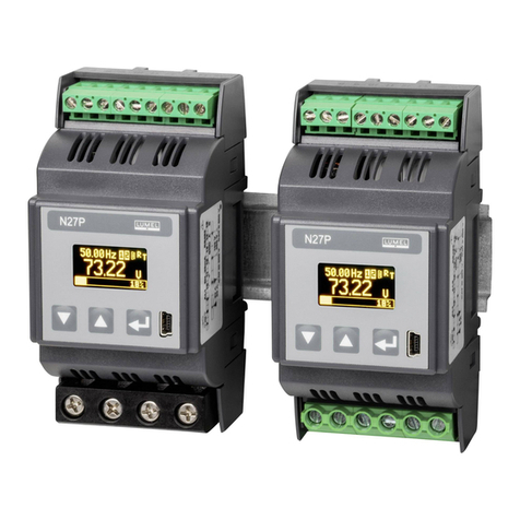
Figure 1. Meter for direct measurements (left)
Meter for indirect measurements (right)

7
3. BASIC REQUIREMENTS, SAFETY OF USE
The symbols used in the manual have the following meaning:
Warning!
Potentially hazardous situations. Read
before connecting the device! Failure
to observe recommendations marked with
this symbol can result in heavy personal
injuries and device damage
Caution!
Generally useful notes. Read them to make
the device use easier. Pay attention to these
notes when the device is not working correctly.
Possible consequences if the information
is disregarded!
In terms of safety of use the meter conforms
to EN 61010-1.
Safety notes:
• Electrical connections should be made by a person with
required licences to install electrical devices.
• Check the correctness of connections before turning
the meter on.
• Removal of the meter cover during the warranty period makes
the warranty null and void.

8
4. INSTALLATION
4.1. Mounting method
The N27P meter can be installed in modular distribu-
tion boards on the 35 mm rail bracket. The meter enclosure is
made of plastic and its dimensions are 53 x 110 x 60.5 mm.
On the outside of the meter there are screw terminal blo-
cks to connect the measurement signals using the leads
up to 5.3 mm2in cross section (1 A / 5 A), and up to 16 mm2
(32 A / 63 A) and the remaining signals using the leads
up to 2.5 mm2. The meter dimensions are shown in Figure 2.
• The meter is intended for installation and use in industrial
electromagnetic environments.
• The building electrical installation should have a switch
or a circuit breaker located near the device, easily
accessible and properly marked.

9
Figure 2. Meter dimensions
The meters shall not be installed on the rail
in direct contact with other heat emitting devices
(e.g. successive N27P meters). Leave the minimum
5-mm space between devices to enable radiation
of heat from the enclosure to the ambient air.
Otherwise, the temperature in direct vicinity
of the meter may exceed the rated operating
temperature.

10
4.2 Connections
The meter connections are shown in Figure 3.
Figure 3. N27P wiring diagrams
63 A
123456
ab
AB
Range 1 A / 5 A
Range 32 A / 63 A

11
5. OPERATION
Figure 4. Front panel
5.1 Description of front panel
Display
USB interface
Control buttons
5.2 Messages after switching the power supply on
After switching the power on, the meter shows infor-
mation about manufacturer, software version and device serial
number. Then the meter goes to display the measured values.

12
6. MENU
6.1 Display
Figure 5. N27P meter display
Data transmission
indicators
R - receiving
T - transmitting
Main displayed
value. Selection
with use of button
„▲”.
USB connection
indicator
Alarm indicators
Upper
displayed
value
Energy
character:
capacitive
inductive
consumed
produced Additional displayed value. Selec-
tionwithuseofbutton„▼”.

13
The main displayed value is selected using the UP button
in the following sequence:
Current Active power
Reactive
power
Apparent
power
Power Factor
Tangent j
Frequency
Voltage
Figure 6. Selecting main displayed value

14
The additional displayed value is selected using the DOWN
button in the following sequence:
Figure 7. Selecting additional displayed value
The upper displayed value is selected from the meter menu
(DISPLAY→UPDISPLAY).
Produced active
energy
Inductive reactive
energy
Apparent
energy
Bargraph
Consumed
active energy Capacitive
reactive energy

15
Note: You can protect the editing of parameters from the display
menu with a password. In such case, it is possible only to view
the meter settings and not to modify them. To set or change
the password use the SERVICE→PASSWORD menu option.
If you forgot the password carry out the following procedure to
remove it:
1. Turn the meter power off
2. Press simultaneously and hold the UP and DOWN buttons
( , ),
3. Turn the meter power on
4. Wait for about 5 seconds and release the buttons
6.2 Menu structure
TheN27Pparametersmaybemodiedfromthedis-
play menu level. and hold it for about 3 seconds. Use the UP
and DOWN buttons ( ) and hold it for about 3 seconds. Use
the UP and DOWN buttons ( , ), to navigate the menu.
To accept choice press ENTER, to cancel or exit press the UP
and DOWN buttons simultaneously or wait 15 seconds. Another
way to go level up is to select the last position on every submenu
(-----).
The menu structure is shown in table 1.

16
Table 1
INPUT
Parameters
of input
VOLTAGE
RANGE
Voltage range of
votalge input
CURRENT
RANGE
Current range of
current input
VOLTAGE RATIO
Voltage transfor-
mer ratio
CURRENT RATIO
Current transfor-
mer ratio
INPUT SYNCH
Input synchroni-
zing method
CLEAR
Counters
reseting
CLR EN COUNT
Reseting energy
counters
CLR AVG
POWER
Reseting
average power
counter
CLR 10 MIN V
Reseting 10-minu-
tes and maximal
values counters
CRL MIN-MAX
Reseting minimal
and maximal
values counters
CRL TIME CNT
Reseting turning-
on counter
DISPLAY
Display
settings
UPPER DISPLAY
Selection of
value displayed
on upper line of
display
BARGRAPH PAR.
Selection of
input parameter
for bargraph
BARGRAPH SYM.
Selection of
bargraph style
BARGRAPH%
Percent of input
parameters as
100% of bargraph
ALARM 1
Alarm 1
setting
INPUT VALUE
Selection of input
signal
OUTPUT TYPE
Selection of
output type
LOW LEVEL IN
Low level of input
signal
HIGH LEVEL IN
High level of input
signal
DELAY ON
Delay for alarm 1
turning on
ALARM 2
Alarm 2
setting
INPUT VALUE
Selection of input
signal
OUTPUT TYPE
Selection of
output type
LOW LEVEL IN
Low level of input
signal
HIGH LEVEL IN
High level of input
signal
DELAY ON
Delay for alarm 2
turning on
OUTPUT
Output
settings
INPUT VALUE
Selection of input
signal
OUTPUT TYPE
Selection of
output type
LOW LEVEL IN
Low level of input
signal
HIGH LEVEL IN
High level of input
signal
LOW LEV OUT
Low level of
output signal
SERVICE
Service
settings
DEFAULT PARAM
Restore factory
settings
PASSWORD
Menu lock
password
TIME
Time settins
DATE
Date settings
LANGUAGE
Selection of
menu language

17
REACT PW
MODE
Reactive power
calculation
method
REACT EN
MODE
Reactive energy
calculation
method
PW AVG SYNCH
Avarage power
synchronization
method
DEMAND POWER
Ordered power
DELAY OFF
Delay for alarm 1
turning off
LOCK TURN ON
Restart interlock
SIGNAL MAINT
Maintenance of
alarm indication
DELAY OFF
Delay for alarm 2
turning off
LOCK TURN ON
Restart interlock
SIGNAL MAINT
Maintenance of
alarm indication
HIGH LEV OUT
High level of
output signal
OUTPUT MODE
Output mode
ERROR VALUE
Output signal
level on error
ADDRESS
Device address
MODE
Transmission
mode
BAUDRATE
Transmis-
sion speed

18
6.3 Programming the inputs
The inputs can be programmed from the INPUTS menu according to
table 2.
INPUTS
Lp. Parameter Parameter
symbol
Range Remarks/Descrip-
tion
Factory
value
1Voltage
range
VOLTAGE
RANGE
100 V, 400 V Selection of input voltage
range
400 V
2Current
range
CURRENT
RANGE
1 A, 5 A (32 A,
63 A)*
Selection of input current
range
5 A (63 A)*
3
Voltage
transformer
ratio
VOLTAGE
RATIO
0,1...4 000,0 1,0
4
Current
transformer
ratio
CURRENT
RATIO
1...10 000 1
5
Input
synchroni-
zation
INPUT
SYNCH
WITH VOL-
TAGE
WITH CUR-
RENT
WITH VOLTAGE (all pa-
rametrs are measured)
WITH CURRENT (cur-
rent and frequency only)
WITH
VOLTAGE
6
Reactive
power
calculation
method
REACT PW
MODE
TRIANGLE
SINUS-HAR-
MON.
TRIANGLE
Q=
√
S2−P2
SINUS-HARMON.
Q=
∑
i=1
k
U
i
⋅I
i
⋅sin (∢U
i
, I
i
)
k – HARMONIC NUM-
BER (21 FOR 50 Hz,
18 FOR 60 Hz)
TRIAN-
GLE
7
Reactive
energy
calculation
method
REACT EN
MODE
CAPAC-INDUC
POSIT-NEGA-
TIVE
CAPAC-IINDUC – capa-
citiv or inductive energy
POSIT-NEGATIVE – po-
sitive or negative energy
CAPAC-
IINDUC
Table 2

19
INPUTS
Lp. Parameter Parameter
symbol
Range Remarks/Descrip-
tion
Factory
value
1Voltage
range
VOLTAGE
RANGE
100 V, 400 V Selection of input voltage
range
400 V
2Current
range
CURRENT
RANGE
1 A, 5 A (32 A,
63 A)*
Selection of input current
range
5 A (63 A)*
3
Voltage
transformer
ratio
VOLTAGE
RATIO
0,1...4 000,0 1,0
4
Current
transformer
ratio
CURRENT
RATIO
1...10 000 1
5
Input
synchroni-
zation
INPUT
SYNCH
WITH VOL-
TAGE
WITH CUR-
RENT
WITH VOLTAGE (all pa-
rametrs are measured)
WITH CURRENT (cur-
rent and frequency only)
WITH
VOLTAGE
6
Reactive
power
calculation
method
REACT PW
MODE
TRIANGLE
SINUS-HAR-
MON.
TRIANGLE
Q=
√
S2−P2
SINUS-HARMON.
Q=
∑
i=1
k
U
i
⋅I
i
⋅sin (∢U
i
, I
i
)
k – HARMONIC NUM-
BER (21 FOR 50 Hz,
18 FOR 60 Hz)
TRIAN-
GLE
7
Reactive
energy
calculation
method
REACT EN
MODE
CAPAC-INDUC
POSIT-NEGA-
TIVE
CAPAC-IINDUC – capa-
citiv or inductive energy
POSIT-NEGATIVE – po-
sitive or negative energy
CAPAC-
IINDUC
8
Synchro-
nization of
average
active
power
PW AVG
SYNCH
MOVING
WINDOW
CLK 15 MIN
CLK 30 MIN
CLK 60 MIN
Average active power
synchronization:
MOVING WINDOW
– 15-minutes moving
window
CLK 15 MIN – measuring
synchronized with clock
every 15-minutes
CLK 30 MIN - measuring
synchronized with clock
every 30-minutes
CLK 60 MIN - measuring
synchronized with clock
every 60-minutes,
MOVING
WINDOW
9
Demand
power
DEMAND
POWER
-144.0
%...144.0 [%]
Demand power to predi-
ct power consumption in
percent of nominal value
100,0 [%]
*) - meter for direct measurements

20
6.4 Reseting counters
Reseting counters can be done from the CLEAR menu
according to table 3.
CLEAR
Lp. Parameter Parameter
symbol
Range Remarks/Descrip-
tion
Factory
value
1
Reseting
energy
counters
CLR EN
COUNT
NO
ACTIVE
REACTIVE
APPARENT
ALL
Reseting active ener-
gy, reactive energy,
apparent energy
counters, or all of
them.
NO
2
Reseting
average
power
counters
CLR 10
MIN V
NO
YES NO
3
Reseting
10-minu-
tes avera-
ge voltage
counter
CLR MIN
MAX
NO
YES NO
4
Reseting
minimal
and maxi-
mal value
counters
KASUJ
MIN-MAX
NO
YES NO
5
Reseting
powering
on counter
CLR TIME
CNT
NO
YES NO
Table 3
Other manuals for N27P
1
Table of contents
Other Lumel Measuring Instrument manuals