Manby Business Park, Manby, Lincolnshire
R1.0 19072018 241837
Typical Wiring Diagram:
Tesng & Commissioning:
•Ensure the power is connected.
•Connect the baery.
•
•
•
Installaon Engineers contact details: Luminaire Reference \ Locaon
Name: Tel:
Luminaire Details:-Full Recharge Duraon 24 Hours Emergency Duraon 3 Hours Lamp Type—LED
ROUTINE TEST RECORD
Year 1 Year 2 Year 3 Year 4 Year 5
Monthly Test Date Date Date Date Date
Three Hour
BATTERY
DRIVER/CHARGER BATTERY CONNECTION
MAINS INPUT
CONNECTION
R2.0 29032021
Manby Business Park, Manby, Lincolnshire
R1.0 19072018 241837
Typical Wiring Diagram:
Tesng & Commissioning:
•Ensure the power is connected.
•Connect the baery.
•
•
•
Installaon Engineers contact details: Luminaire Reference \ Locaon
Name: Tel:
Luminaire Details:-Full Recharge Duraon 24 Hours Emergency Duraon 3 Hours Lamp Type—LED
ROUTINE TEST RECORD
Year 1 Year 2 Year 3 Year 4 Year 5
Monthly Test Date Date Date Date Date
Three Hour
BATTERY
DRIVER/CHARGER BATTERY CONNECTION
MAINS INPUT
CONNECTION
1
EMERGENCY BULKHEAD INSTRUCTIONS
SAFETY This is a mains powered product. It is designed to be installed by suitably qualified personnel only and in
accordance with the applicable building and electrical regulations. Before installation or maintenance the electrical
supply to the product must be isolated.
WARRANTY This product is warranted to be free of defects in materials, design and workmanship for 3 years from the date of
purchase. If a suspected fault should develop in t This warranty does
not include batteries or consumable items such as fuses.
INSTALLATION SUPPORT If installation advice or accessories are required please also contact us on the number above. We
will do our best to help. When reporting a suspected fault or seeking installation support the problem is likely to be resolved most
quickly if you have full product details to-hand, as well as details of when and where it was purchased.
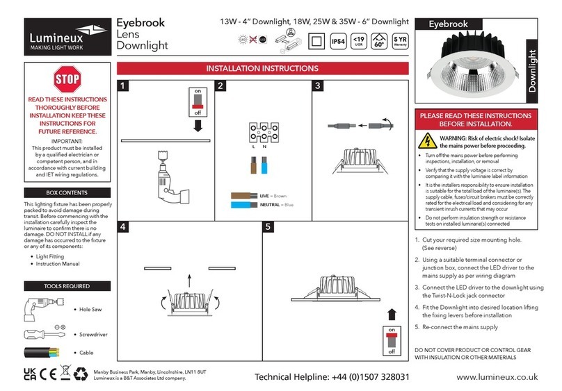
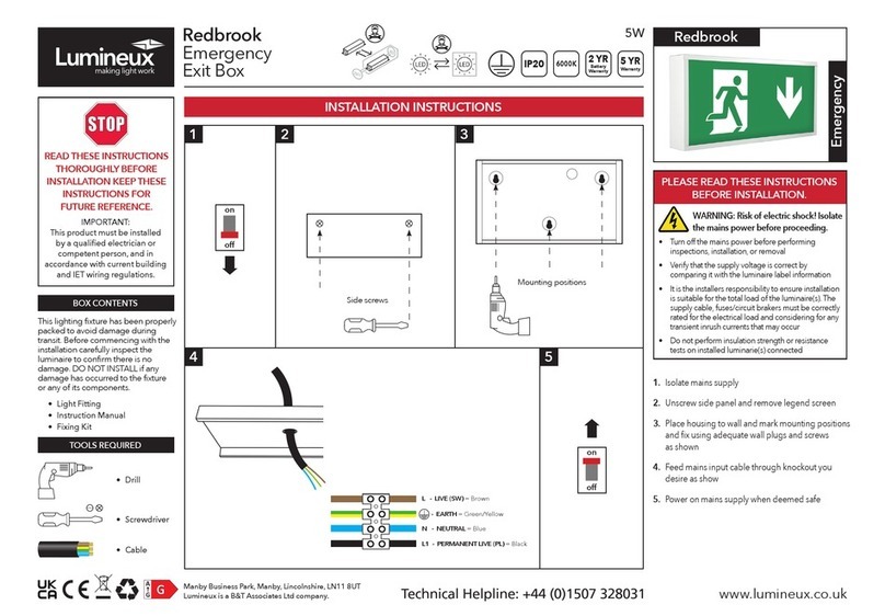
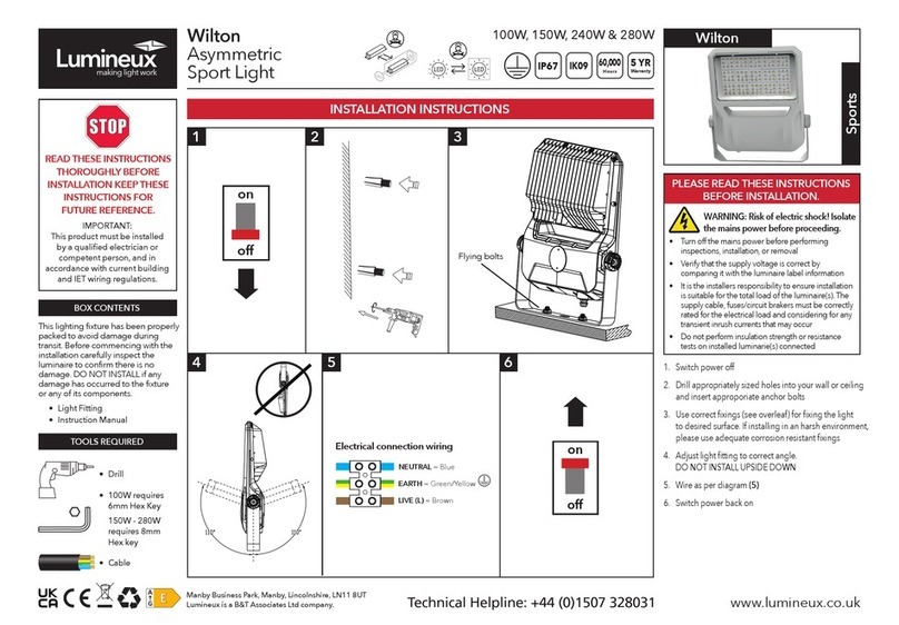
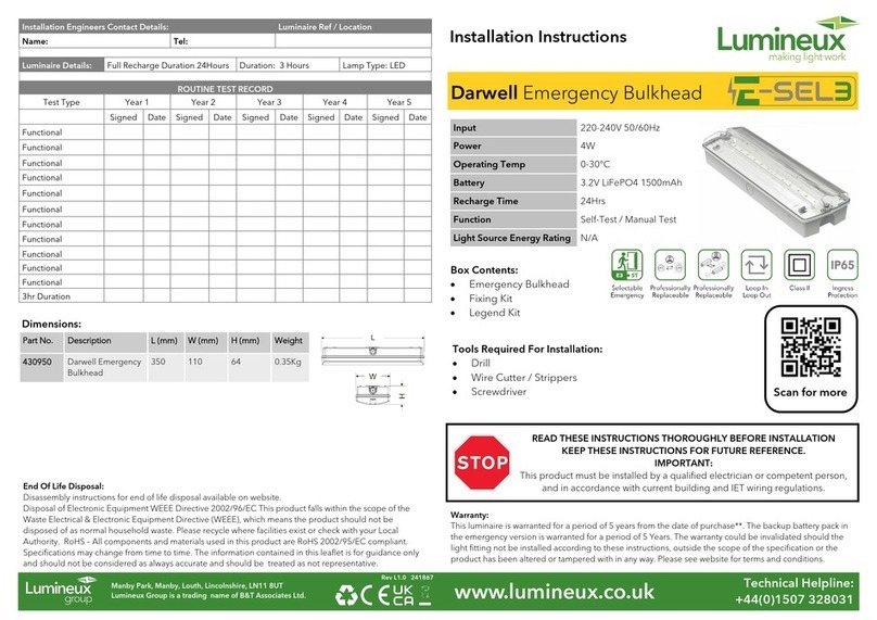
LUMINAIRE INSTALLATION
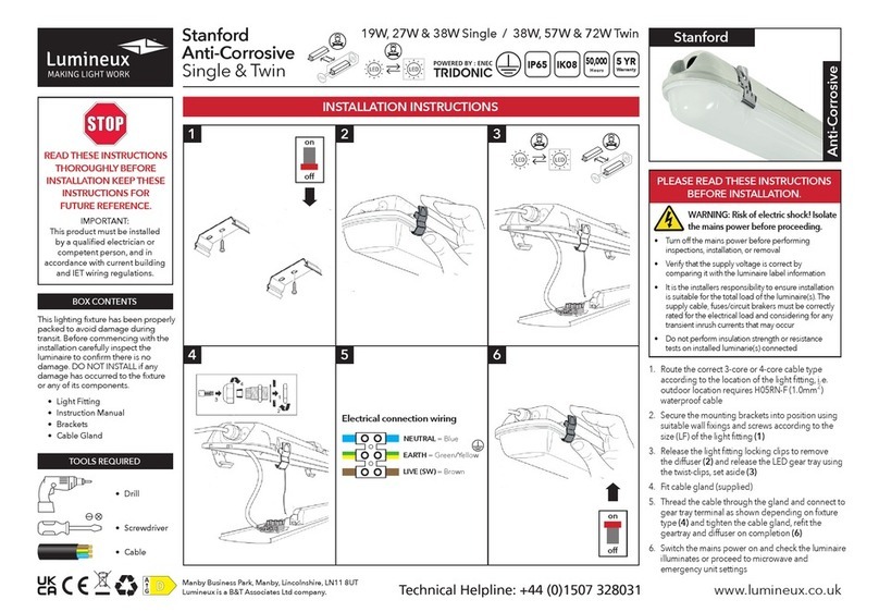
1. Remove diffuser by unscrewing the two screws.
2. Hinge the gear tray open by pushing apart the two retaining clips.
3. Screw fix the base to the chosen mounting surface using the two screw
fixing points in the base moulding at 240mm centres. These should be
drilled to a size to suit the fixing screws.
Note: It is responsibility of the installer to ensure these fixing points
are sealed to ensure the IP65 rating is maintained. The use of a
silicone sealant is recommended.
4. Select one of the available cable entry points on the base (one on either
end, on one side, or through the bottom) & drill to suitable size to suit IP65
rated (or better) cable entry gland (not provided).
5. Install cable entry gland.
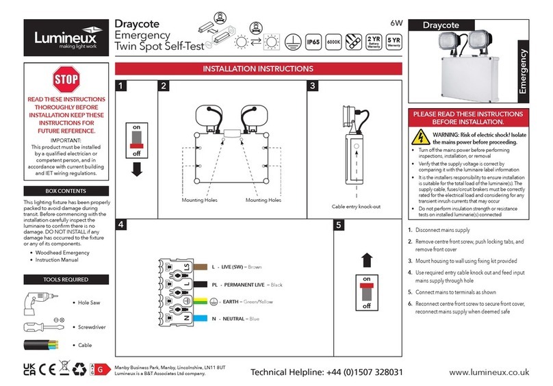
6. Depending on which variant of the product you have, determine your required function & route the appropriate power
supply cable to the terminal block & terminate as shown.
7. If applicable, tighten cable gland to seal & secure mains cable.
8. Connect the battery pack to the PCB by connecting the female socket on the battery wires to the male plug mounted on
the PCB, ensuring the correct orientation.
9. Enter the “Installation Date” in the appropriate place on the battery pack label.
10. Hinge the gear tray closed & snap fit of clips to secure.
11. Refit the diffuser & secure using the two screws.
12. Reconnect the power supply & check the green LED charge indicator illuminates.
13. The batteries should be allowed to charge for at least 24 hours before carrying out a full discharge test to check they are
charging correctly & the maintained duration is being achieved.
OPERATION / MAINTENANCE
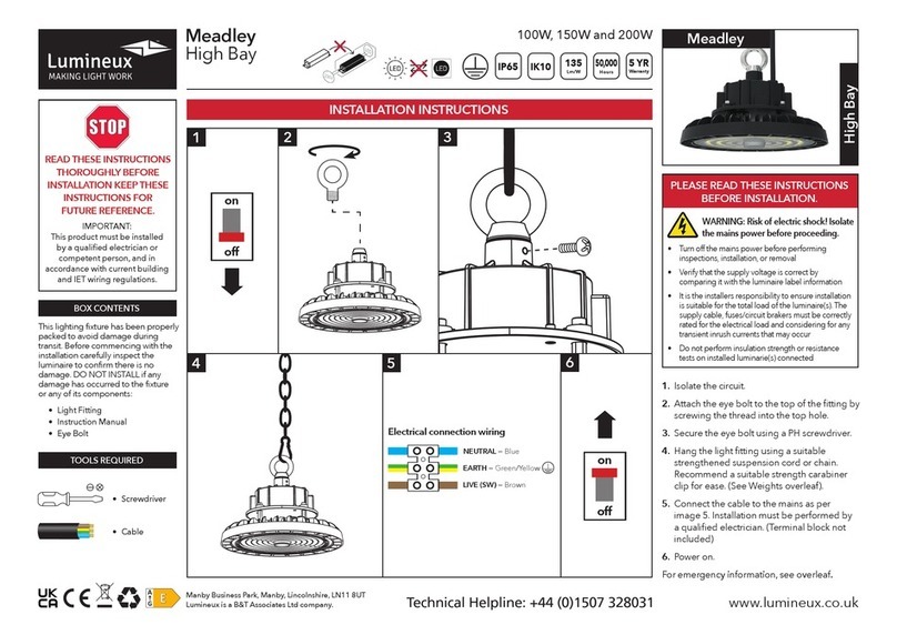
1. Nominal battery life is 2 years, after which time they should be replaced with a suitable equivalent.
2. This luminaire MUST be disconnected before the circuit it is installed on is subjected to any high voltage or insulation
resistance testing, otherwise irreparable damage will occur to luminaire components.
3. Ensure cleanliness of luminaires is maintained so as not to affect performance.
RECESSED MOUNT KIT INSTALLATION –
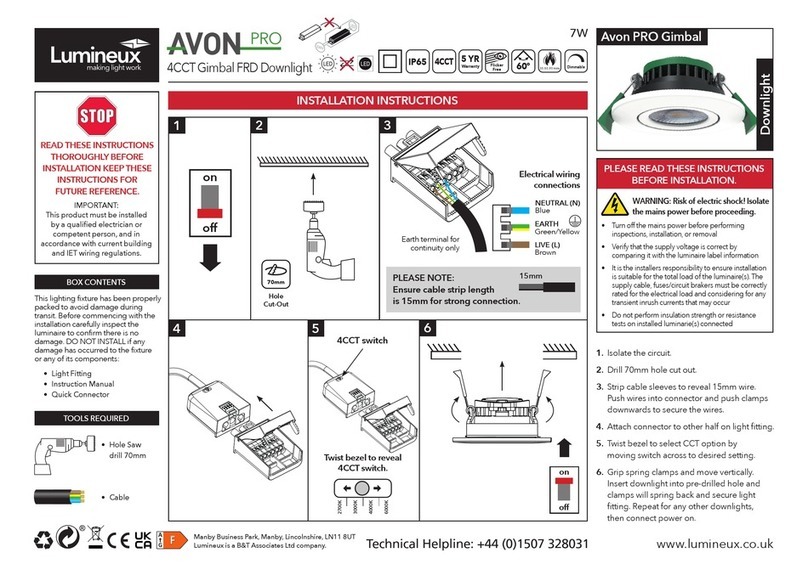
1. Prepare ceiling by cutting suitable size aperture. We recommend 360mm x 110mm.
2. Bend springs up to vertical & push the back of the frame up through aperture, then allow the springs to snap back
against the top of the ceiling to retain.
3. Drill out the two fixing points at 240mm centres in the base of the luminaire & then secure the base to the frame using 2-
off M4 screws aligned with the tapped holes on the brackets of the frame.
4. Other installation details as per LUMINAIRE INSTALLATION section above.
DROP DOWN ATTACHMENT INSTALLATION –
1. Remove the standard diffuser on the main product by undoing the two screws.
2. Install the Drop Down Attachment on the main luminaire body & secure using the two screws.
3. Apply the required emergency legends (supplied with the attachment) to both sides of the attachment.
TESTING FOR EMERGENCY LUMINAIRES
Recommended routine test procedures in line with BS 5266 & BS EN 50172:
Monthly Functional Test
• Simulate a mains supply failure by isolating the circuit (ensuring if it is safe to do so) or by way of a test key switch if
fitted into the circuit.
• Do this for a period of time sufficient to check that the light source illuminates from the battery supply.
• Once complete, ensure the normal supply is restored & that the green LED charge indicator illuminates.
• Log result/comments in the Testing Log Book.
Annual Discharge Test
• Simulate a mains supply failure by isolating the circuit (ensuring if it is safe to do so) or by way of a test key switch if
fitted into the circuit.
• This should be for the full 3-hour rated duration.
• Check that the light source illuminates & remains illuminated for the full rated duration period.
• Once complete, ensure the normal supply is restored & that the green LED charge indicator illuminates.
• Log result/comments in the Testing Log Book.
TESTING LOG BOOK
Luminaire Type: ……………………………… Luminaire Location/No.: ………………………………...
Installed By: ……………………………… Installed Date: ……………………….....................
Contact Details: …………………………………………………………………………………………………………………………..
…………………………………………………………………………………………………………………………..
MONTH
T EST
Signed Date Signed Date Signed Date Signed Date Signed Date
1
FUNCTION AL
2
FUNCTION AL
3
FUNCTION AL
4
FUNCTION AL
5
FUNCTION AL
6
FUNCTION AL
7
FUNCTION AL
8
FUNCTION AL
9
FUNCTION AL
10
FUNCTION AL
11
FUNCTION AL
12
DISCHARGE
FIFTH YEARFIRST YEAR SECOND YEAR THIRD YEAR FORTH YEAR
1
EMERGENCY BULKHEAD INSTRUCTIONS
SAFETY This is a mains powered product. It is designed to be installed by suitably qualified personnel only and in
accordance with the applicable building and electrical regulations. Before installation or maintenance the electrical
supply to the product must be isolated.
WARRANTY This product is warranted to be free of defects in materials, design and workmanship for 3 years from the date of
purchase. If a suspected fault should develop in t This warranty does
not include batteries or consumable items such as fuses.
INSTALLATION SUPPORT If installation advice or accessories are required please also contact us on the number above. We
will do our best to help. When reporting a suspected fault or seeking installation support the problem is likely to be resolved most
quickly if you have full product details to-hand, as well as details of when and where it was purchased.
LUMINAIRE INSTALLATION
1. Remove diffuser by unscrewing the two screws.
2. Hinge the gear tray open by pushing apart the two retaining clips.
3. Screw fix the base to the chosen mounting surface using the two screw
fixing points in the base moulding at 240mm centres. These should be
drilled to a size to suit the fixing screws.
Note: It is responsibility of the installer to ensure these fixing points
are sealed to ensure the IP65 rating is maintained. The use of a
silicone sealant is recommended.
4. Select one of the available cable entry points on the base (one on either
end, on one side, or through the bottom) & drill to suitable size to suit IP65
rated (or better) cable entry gland (not provided).
5. Install cable entry gland.
6. Depending on which variant of the product you have, determine your required function & route the appropriate power
supply cable to the terminal block & terminate as shown.
7. If applicable, tighten cable gland to seal & secure mains cable.
8. Connect the battery pack to the PCB by connecting the female socket on the battery wires to the male plug mounted on
the PCB, ensuring the correct orientation.
9. Enter the “Installation Date” in the appropriate place on the battery pack label.
10. Hinge the gear tray closed & snap fit of clips to secure.
11. Refit the diffuser & secure using the two screws.
12. Reconnect the power supply & check the green LED charge indicator illuminates.
13. The batteries should be allowed to charge for at least 24 hours before carrying out a full discharge test to check they are
charging correctly & the maintained duration is being achieved.
OPERATION / MAINTENANCE
1. Nominal battery life is 2 years, after which time they should be replaced with a suitable equivalent.
2. This luminaire MUST be disconnected before the circuit it is installed on is subjected to any high voltage or insulation
resistance testing, otherwise irreparable damage will occur to luminaire components.
3. Ensure cleanliness of luminaires is maintained so as not to affect performance.
RECESSED MOUNT KIT INSTALLATION –
1. Prepare ceiling by cutting suitable size aperture. We recommend 360mm x 110mm.
2. Bend springs up to vertical & push the back of the frame up through aperture, then allow the springs to snap back
against the top of the ceiling to retain.
3. Drill out the two fixing points at 240mm centres in the base of the luminaire & then secure the base to the frame using 2-
off M4 screws aligned with the tapped holes on the brackets of the frame.
4. Other installation details as per LUMINAIRE INSTALLATION section above.
