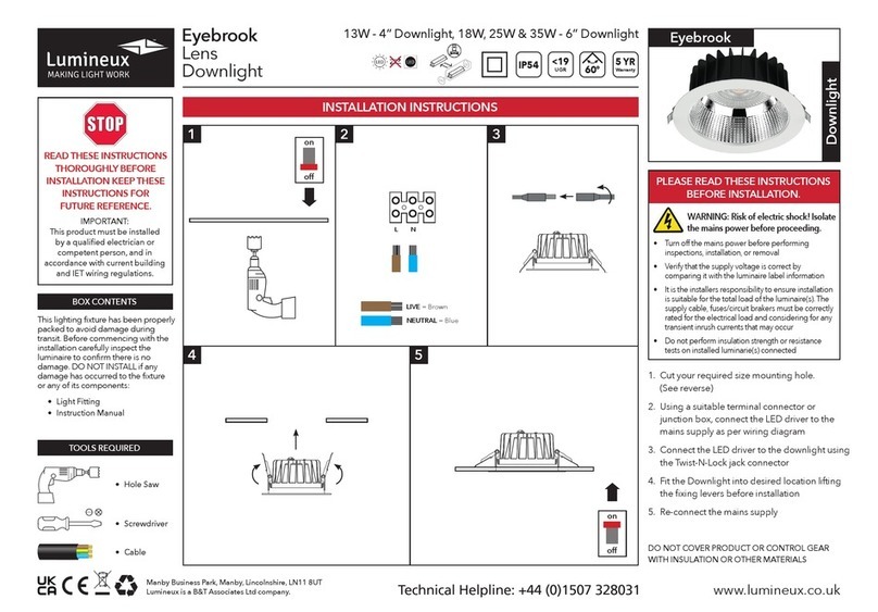
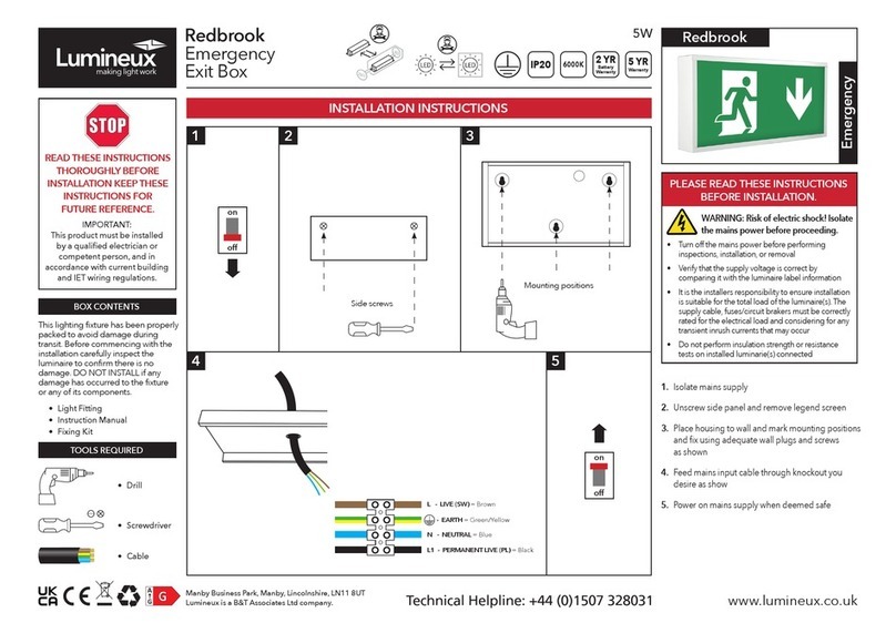
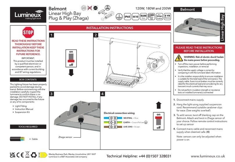
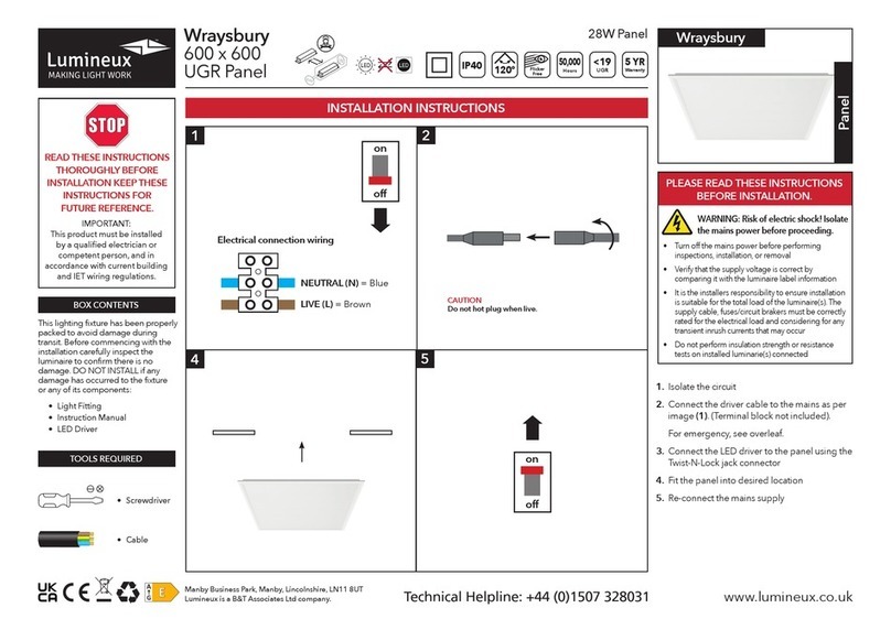
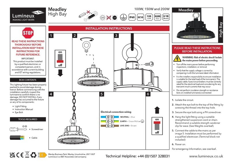
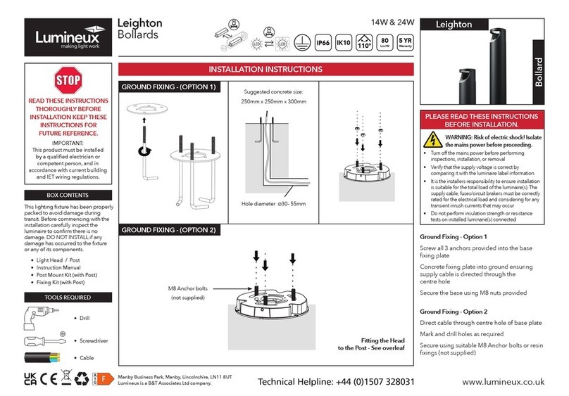
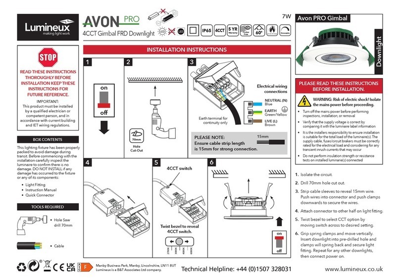
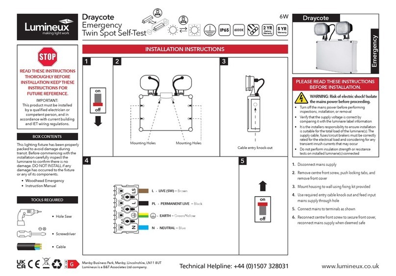
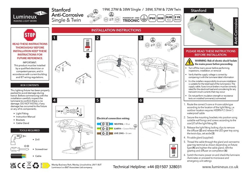
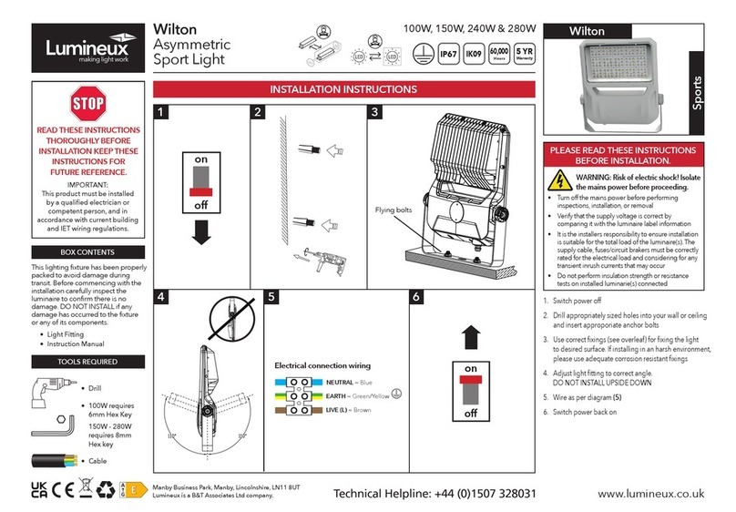
WARNING: Risk of electric shock!
Isolate the mains power before proceeding.
• Turn o the mains power before performing inspections, installation, or removal
• Verify that the supply voltage is correct by comparing it with the luminaire label information
• It is the installers responsibility to ensure installation is suitable for the total load of the luminaire(s). The
supply cable, fuses/circuit breakers must be correctly rated for the electrical load and considering for any
transient inrush currents that may occur.
• Do not perform insulation strength or resistance tests on installed luminarie(s) connected
Wiring instructions for units equipped an with EMERGENCY function:
Emergency lighting luminaries must be installed and maintained in accordance with the emergency lighting
standard BS 5266-1
• For the emergency unit to work correctly, please ensure that an uninterrupted permanent live feed is
present and is connected directly to the ‘Permanent Live’ terminal of the mains terminal block. Please
ensure there are no switches, PIRs etc within the permanent live feed, constant switching of the
emergency pack could result in premature battery failure.
• Following power up the green LED indicator should illuminate to indicate charging. If power to the unit is
disrupted or isolated, the unit indicating green LED will switch o, triggering the emergency LEDs to
illuminate.
• When self-test mode is selected, 24hrs from connection to mains power, a 3hrs duration test will be
performed automatically.
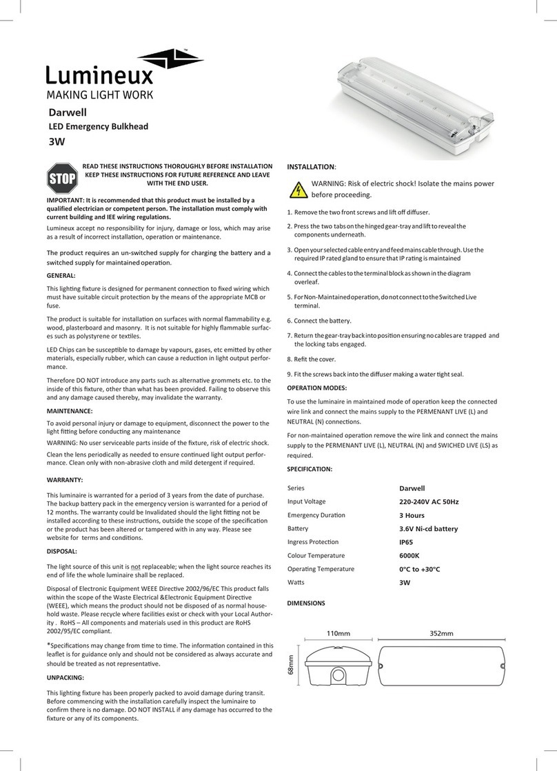
1. Unscrew and remove the cover.
2. Open geartray and drill the required mounting holes in the base
and mount into desired location using suitable xing method.
3. Wire the incoming supply.
4. Connect the battery.
5. Select your Maintained (PM1) / Non-Maintained operation (PM2).
6. Select your required function, Self-test (EL-T) / Manual test (EL).
7. Ret geartray and diuser.
8. Reconnect mains supply.
Installation Procedure:
Colour LED Indication Status
Green Permanent Green Normal Function
Green Fast Flashing Green (0.1 sec on, 0.1 sec o) Function Test In Progress
Green Slow Flashing Green (1 sec on, 1 sec o) Duration Test In Progress
Red Permanent Red Load Failure
Red Slow Flashing Red (1 sec on, 1 sec o) Battery Failure
Emergency Indication:
1. 2.
3. 4.
7. 8.
Permanent Live
to L Terminal
Neutral to N Terminal
Connect baery to terminal
Maintained
5. 6.
Non-
Maintained
ON
Self-
Test
Manual
Test
To reset unit after failure, press and hold button located next to battery terminal for 5 seconds.
