manuals.online logo
Brands
  1. Home
  2. •
  3. Brands
  4. •
  5. Lumineux
  6. •
  7. Lighting Equipment
  8. •
  9. Lumineux 430520-120 User manual

Lumineux 430520-120 User manual

This manual suits for next models

5

Other Lumineux Lighting Equipment manuals

Lumineux Darwell User manual

Lumineux

Lumineux Darwell User manual

Lumineux Leighton 14W User manual

Lumineux

Lumineux Leighton 14W User manual

Lumineux Draycote User manual

Lumineux

Lumineux Draycote User manual

Lumineux Eyebrook User manual

Lumineux

Lumineux Eyebrook User manual

Lumineux Avon PRO 4CCT User manual

Lumineux

Lumineux Avon PRO 4CCT User manual

Lumineux Belmont User manual

Lumineux

Lumineux Belmont User manual

Lumineux 421301 User manual

Lumineux

Lumineux 421301 User manual

Lumineux Wraysbury User manual

Lumineux

Lumineux Wraysbury User manual

Lumineux Darwell 421061 User manual

Lumineux

Lumineux Darwell 421061 User manual

Lumineux Redbrook 421065 User manual

Lumineux

Lumineux Redbrook 421065 User manual

Lumineux Wraysbury User manual

Lumineux

Lumineux Wraysbury User manual

Lumineux Stanford Anti-Corrosive User manual

Lumineux

Lumineux Stanford Anti-Corrosive User manual

Lumineux Wilton 430711 User manual

Lumineux

Lumineux Wilton 430711 User manual

Popular Lighting Equipment manuals by other brands

Life 39.9F70020C quick start guide

Life

Life 39.9F70020C quick start guide

EuroLite LED ML-20 user manual

EuroLite

EuroLite LED ML-20 user manual

LIGMAN OD-50141 installation manual

LIGMAN

LIGMAN OD-50141 installation manual

Home Accents Holiday 1002461144 instructions

Home Accents Holiday

Home Accents Holiday 1002461144 instructions

Experia IRiS Ripple Light instruction manual

Experia

Experia IRiS Ripple Light instruction manual

Erco Gecko Mounting instructions

Erco

Erco Gecko Mounting instructions

Inter-lux ZTA.100.Surface Installation and maintenance instructions

Inter-lux

Inter-lux ZTA.100.Surface Installation and maintenance instructions

Whelen Engineering Company TN Series installation guide

Whelen Engineering Company

Whelen Engineering Company TN Series installation guide

IKEA BJÖRKSPIREA manual

IKEA

IKEA BJÖRKSPIREA manual

Toolland PM 6640 instruction manual

Toolland

Toolland PM 6640 instruction manual

GTD GTD-LP200 user manual

GTD

GTD GTD-LP200 user manual

LIVARNO home 1105-W-UK manual

LIVARNO home

LIVARNO home 1105-W-UK manual

ProLights EclPar IPMFC user manual

ProLights

ProLights EclPar IPMFC user manual

Velvet EVO Series user manual

Velvet

Velvet EVO Series user manual

IDTOLIGHT GENT installation instructions

IDTOLIGHT

IDTOLIGHT GENT installation instructions

MAYTONI S35 installation manual

MAYTONI

MAYTONI S35 installation manual

MaxLite MLFP14DP4535 user manual

MaxLite

MaxLite MLFP14DP4535 user manual

SLV Elektronik 550621 instruction manual

SLV Elektronik

SLV Elektronik 550621 instruction manual

manuals.online logo
manuals.online logoBrands
  • About & Mission
  • Contact us
  • Privacy Policy
  • Terms and Conditions

Copyright 2025 Manuals.Online. All Rights Reserved.

READ THESE INSTRUCTIONS
THOROUGHLY BEFORE
INSTALLATION KEEP THESE
INSTRUCTIONS FOR
FUTURE REFERENCE.
IMPORTANT:
This product must be installed
by a qualied electrician or
competent person, and in
accordance with current building
and IET wiring regulations.
• Light Fitting
• Instruction Manual
• Eye Bolt
Meadley
High Bay
100W, 150W and 200W
Technical Helpline: +44 (0)1507 328031
www.lumineux.co.uk
Meadley
High Bay
TOOLS REQUIRED
BOX CONTENTS
• Cable
• Screwdriver
This lighting xture has been properly
packed to avoid damage during
transit. Before commencing with the
installation carefully inspect the
luminaire to conrm there is no
damage. DO NOT INSTALL if any
damage has occurred to the xture
or any of its components:
• Turn off the mains power before performing
inspections, installation, or removal
• Verify that the supply voltage is correct by
comparing it with the luminaire label information
• It is the installers responsibility to ensure installation
is suitable for the total load of the luminaire(s). The
supply cable, fuses/circuit brakers must be correctly
rated for the electrical load and considering for any
transient inrush currents that may occur
• Do not perform insulation strength or resistance
tests on installed luminarie(s) connected
PLEASE READ THESE INSTRUCTIONS
BEFORE INSTALLATION.
WARNING: Risk of electric shock! Isolate
the mains power before proceeding.
2
1
6
4 5
3
on
off
INSTALLATION INSTRUCTIONS
on
off
IP65
Warranty
5 YR
Hours
50,000
IK10
Lm/W
135
1. Isolate the circuit.
2. Attach the eye bolt to the top of the tting by
screwing the thread into the top hole.
3. Secure the eye bolt using a PH screwdriver.
4. Hang the light tting using a suitable
strengthened suspension cord or chain.
Recommend a suitable strength carabiner
clip for ease. (See Weights overleaf).
5. Connect the cable to the mains as per
image 5. Installation must be performed by
a qualied electrician. (Terminal block not
included)
6. Power on.
For emergency information, see overleaf.
Electrical connection wiring
LIVE (SW) = Brown
NEUTRAL = Blue
EARTH = Green/Yellow
Manby Business Park, Manby, Lincolnshire, LN11 8UT
Lumineux is a B&T Associates Ltd company.
EE
A
G
ROUTINE TEST RECORD
Type Test Year 1 Year 2 Year 3 Year 4 Year 5
Signed Date Signed Date Signed Date Signed Date Signed Date
Functional 1
Functional 2
Functional 3
Functional 4
Functional 5
Functional 6
Functional 7
Functional 8
Functional 9
Functional 10
Functional 11
3hr Duration 12
Installation Engineers Contact Details: Luminaire Reference / Location
Name: Tel:
Luminaire Details: Full Recharge Duration 24 Hours Emergency Duration 3 Hours Lamp Type LED
Meadley High Bay
The light source of this unit is not
replaceable; when the light source
reaches its end of life the whole
luminaire shall be replaced.
Disassembly instructions for end of
life disposal available on website.
Disposal of Electronic Equipment
WEEE Directive 2002/96/EC This
product falls within the scope of
the Waste Electrical & Electronic
Equipment Directive (WEEE), which
means the product should not be
disposed of as normal household
waste. Please recycle where
facilities exist or check with your
Local Authority. RoHS – All
components and materials used in
this product are RoHS 2002/95/EC
compliant.
Specications may change from time
to time. The information contained
in this leaet is for guidance only
and should not be considered as
always accurate and should be
treated as not representative.
Standard -20º to +45ºC
Emergency 0 to +30ºC
DISPOSAL
WARRANTY
PRODUCT TEMP SPECIFICATION
Part No. Description Watts L(mm) W(mm) H(mm) Weight
430520-120 Meadley High Bay 100W 223 223 168 1.85Kg
430521-120 Meadley High Bay 150W 276 276 168 2.2Kg
430522-120 Meadley High Bay 200W 329 329 168 2.7Kg
430520-90 Meadley High Bay 100W 223 223 168 1.8Kg
430521-90 Meadley High Bay 150W 276 276 168 2.2Kg
430522-90 Meadley High Bay 200W 329 329 168 2.7Kg
MEADLEY DIMENSIONS
Revision 2 - April 2022
L (mm)
H (mm)
W (mm)
This luminaire is warranted for a
period of 5 years from the date of
purchase.** The backup battery
pack in the emergency version
is warranted for a period of 24
months. The warranty could be
invalidated should the light tting
not be installed according to these
instructions, outside the scope of
the specication or the product
has been altered or tampered with
in any way. Please see website for
terms and conditions.
** Please see our website for more detailed information on warranty. Technical Helpline: +44 (0)1507 328031
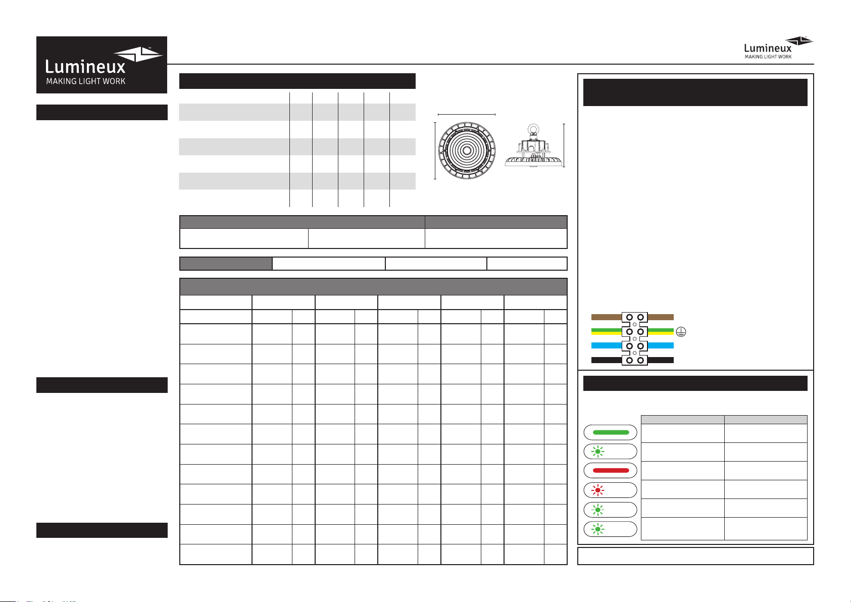
1. Connect incoming earth cable to ‘Earth’ terminal on connector block.
2. Connect incoming neutral cable to ‘Neutral’ terminal on connector block.
3. For the emergency unit to work correctly, please ensure that an
uninterrupted permanent live feed is present and is connected directly
to the ‘Permanent Live’ terminal of the mains terminal block. Please
ensure there are no switches, PIRs etc within the permanent live feed,
constant switching of the emergency pack could result in premature
battery failure.
4. Connect incoming switched live cable to the terminal marked
“Switched Live”
NOTE: If there is no switch live feed and the unit has a microwave sensor,
simply bridge across from the “Permanent Live” to the Switch Live” on the
mains terminal block.
5. There should be a loose ying lead connected to the battery. This needs
to be attached to the ying lead from the emergency control unit.
6. Following power up the green LED indicator should illuminate to indicate
charging. If power to the unit is disrupted or isolated, the unit indicating
green LED will switch off, triggering the emergency LEDs to illuminate.
7. Please allow 24 hours charge before rst emergency test.
The self-test version of emergency is tted with control gear that will carry out
periodic functional tests every 1 month and full duration test every 12 months.
Wiring instructions for units equipped
an with EMERGENCY function
Self-Test EMERGENCY function
Emergency lighting luminaries must be installed and maintained in
accordance with the emergency lighting standard BS 5266-1
Fault/Test/Status Reason
Battery fully charged
and operational Standard daily use
Battery Charging Initial charge /
battery topping up
Battery Failure Battery is disconnected or
damaged/faulty
Duration Test Failure Maintenance check required
by qualied engineer
Automatic Testing - Function
5 minute test (Every 30 days)
Self-testing in
operation
Automatic Testing -
Duration test is 3 hours
(every 12 months)
Self-testing in
operation
Charge Indicator Status
Battery Fully Charged
and Operational
Battery Charging
Auto Test 5 Min
(every 30 days)
Auto Test 3 Hours
(every 12 months)
Duration Test Failure
1 Sec ON
1 Sec OFF
3 Sec ON
3 Sec OFF
3 Sec ON
1 Sec OFF
0.5 Sec ON
0.5 Sec OFF
Battery
Disconnected/Faulty
This product contains a light source of energy efciency Class E.
EMERGENCY FITTINGS ONLY. EARTH CONNECTION REQUIRED.
L - LIVE (SW) = Brown
N - NEUTRAL = Blue
L1 - PERMANENT LIVE (PL) = Black
- EARTH = Green/Yellow