manuals.online logo
Brands
  1. Home
  2. •
  3. Brands
  4. •
  5. Lumineux
  6. •
  7. Lighting Equipment
  8. •
  9. Lumineux Stanford Anti-Corrosive User manual

Lumineux Stanford Anti-Corrosive User manual

READ THESE INSTRUCTIONS
THOROUGHLY BEFORE
INSTALLATION KEEP THESE
INSTRUCTIONS FOR
FUTURE REFERENCE.
IMPORTANT:
This product must be installed
by a qualifi ed electrician or
competent person, and in
accordance with current building
and IET wiring regulations.
• Light Fitting
• Instruction Manual
• Brackets
• Cable Gland
Stanford
Anti-Corrosive
Single & Twin
19W, 27W & 38W Single / 38W, 57W & 72W Twin
IP65
Warranty
5 YR
Hours
50,000
Manby Business Park, Manby, Lincolnshire, LN11 8UT
Lumineux is a B&T Associates Ltd company.
Technical Helpline: +44 (0)1507 328031
www.lumineux.co.uk
1 2
5
3
6
on
off
4
Stanford
Anti-Corrosive
1. Route the correct 3-core or 4-core cable type
according to the location of the light  tting, i.e.
outdoor location requires H05RN-F (1.0mm2)
waterproof cable
2. Secure the mounting brackets into position using
suitable wall  xings and screws according to the
size (LF) of the light  tting (1)
3. Release the light  tting locking clips to remove
the diffuser (2) and release the LED gear tray using
the twist-clips, set aside (3)
4. Fit cable gland (supplied)
5. Thread the cable through the gland and connect to
gear tray terminal as shown depending on  xture
type (4) and tighten the cable gland, re t the
geartray and diffuser on completion (6)
6. Switch the mains power on and check the luminaire
illuminates or proceed to microwave and
emergency unit settings
IK08
POWERED BY : ENEC
TOOLS REQUIRED
BOX CONTENTS
• Drill
• Screwdriver
• Cable
INSTALLATION INSTRUCTIONS
on
off
This lighting  xture has been properly
packed to avoid damage during
transit. Before commencing with the
installation carefully inspect the
luminaire to con rm there is no
damage. DO NOT INSTALL if any
damage has occurred to the  xture
or any of its components.
• Turn off the mains power before performing
inspections, installation, or removal
• Verify that the supply voltage is correct by
comparing it with the luminaire label information
• It is the installers responsibility to ensure installation
is suitable for the total load of the luminaire(s). The
supply cable, fuses/circuit brakers must be correctly
rated for the electrical load and considering for any
transient inrush currents that may occur
• Do not perform insulation strength or resistance
tests on installed luminarie(s) connected
PLEASE READ THESE INSTRUCTIONS
BEFORE INSTALLATION.
WARNING: Risk of electric shock! Isolate
the mains power before proceeding.
DD
A
G
Electrical connection wiring
LIVE (SW) = Brown
NEUTRAL = Blue
EARTH = Green/Yellow
ROUTINE TEST RECORD
Type Test Year 1 Year 2 Year 3 Year 4 Year 5
Signed Date Signed Date Signed Date Signed Date Signed Date
Functional 1
Functional 2
Functional 3
Functional 4
Functional 5
Functional 6
Functional 7
Functional 8
Functional 9
Functional 10
Functional 11
3hr Duration 12
Installation Engineers Contact Details: Luminaire Reference / Location
Name: Tel:
Luminaire Details: Full Recharge Duration 24 Hours Emergency Duration 3 Hours Lamp Type LED
Stanford Anti-Corrosive
This luminaire is warranted for a
period of 5 years from the date of
purchase**. The backup battery
pack in the emergency version
is warranted for a period of 24
months. The warranty could be
invalidated should the light tting
not be installed according to these
instructions, outside the scope of
the specication or the product
has been altered or tampered with
in any way. Please see website for
terms and conditions.
Standard -20 to +40ºC
Emergency 0 to +30ºC
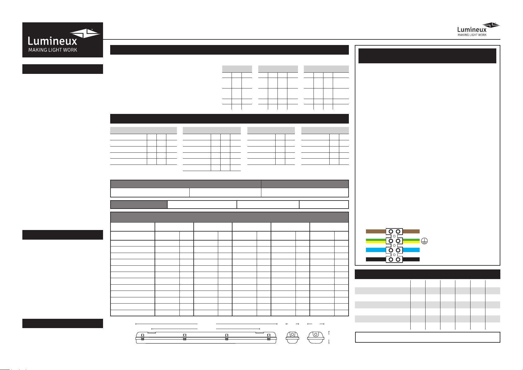
1. Connect incoming earth cable to ‘Earth’ terminal on connector block.
2. Connect incoming neutral cable to ‘Neutral’ terminal on connector
block.
3. For the emergency unit to work correctly, please ensure that an
uninterrupted permanent live feed is present and is connected
directly to the ‘Permanent Live’ terminal of the mains terminal block.
Please ensure there are no switches, PIRs etc within the permanent
live feed, constant switching of the emergency pack could result
in premature battery failure.
4. Connect incoming switched live cable to the terminal marked
“Switched Live”
NOTE: If there is no switch live feed and the unit has a microwave
sensor, simply bridge across from the “Permanent Live” to the Switch
Live” on the mains terminal block.
5. There should be a loose ying lead connected to the battery.
This needs to be attached to the ying lead from the emergency
control unit.
6. Following power up the green LED indicator should illuminate to
indicate charging. If power to the unit is disrupted or isolated, the
unit indicating green LED will switch off, triggering the emergency
LEDs to illuminate.
7. Please allow 24 hours charge before rst emergency test.
Technical Helpline: +44 (0)1507 328031
Wiring instructions for units equipped
an with EMERGENCY function
DISPOSAL
WARRANTY
PRODUCT TEMP SPECIFICATION
Detection Range: This determines the effective
range of the motion. Note that reducing the
sensitivity will also narrow the detection range.
Hold Time Duration: This determines the
time the tting remains at 100% illumination
following motion detection.
Daylight Setting: This setting holds off the 100%
light output should there be sufcient daylight.
STANDARD ON/OFF SENSOR
MICROWAVE SENSOR SETTINGS
STEP DIM DRIVER SETTINGS
LENGTH
LF
W W
H
Detection Area
1 2
ON ON 100%
OFF ON 75%
ON OFF 50%
OFF OFF 25%
- - -
- - -
OUTPUT CURRENT SETTING
Output Current (mA) S1 S2 S3
1200 ON ON ON
1050 ON ON -
900 ON - -
800 - - -
DAYLIGHT SENSOR
Daylight Sensor S1 S2 S3
Disable* ON ON ON
100Lux ON ON -
50Lux ON - ON
30Lux - ON ON
10Lux - - -
STAND-BY-PERIOD
Stand-by-Period S4 S5
1 Min ON ON
5 Min ON -
25 Min - ON
+∞ - -
SENSITIVITY
Sensitivity S1 S2
100% ON ON
75% ON -
50% - ON
25% - -
HOLD TIME
3 4 5
ON ON ON 5S
OFF ON ON 30S
ON OFF ON 90S
OFF OFF ON 5Min
ON ON OFF 20Min
OFF OFF OFF 30Min
DAYLIGHT
6 7 8
ON ON ON 2Lux
ON ON OFF 10Lux
OFF ON OFF 30Lux
ON OFF OFF 50Lux
OFF OFF OFF Disable
- - - -
Part No. Description Watts L(mm) W(mm) H(mm) LF (mm) Weight
430026 / 430032 4ft Single 19W
1274 100 90 900
1.62Kg
430028 / 430034 5ft Single 27W
1574 100 90 1200
1.62Kg
430030 / 430036 6ft Single 38W
1837 100 90 1150
1.96Kg
430027 / 430033 4ft Twin 38W
1274 140 90 900
1.96Kg
430029 / 430035 5ft Twin 57W
1574 140 90 1200
2.30Kg
430031 / 430037 6ft Twin 72W
1837 140 90 1150
2.30Kg
STANFORD ANTI-CORROSIVE DIMENSIONS
*Sensor is disabled and will not detect daylight
+∞ Lights remain constant at low level Set via detachable sensor
Emergency lighting luminaries must be installed and maintained
in accordance with the emergency lighting standard BS 5266-1
Revision 2 - February 2022
This product contains a light source of energy efciency Class D.
EMERGENCY FITTINGS ONLY. EARTH CONNECTION REQUIRED.
L - LIVE (SW) = Brown
N - NEUTRAL = Blue
L1 - PERMANENT LIVE (PL) = Black
- EARTH = Green/Yellow
Disassembly instructions for end of
life disposal available on website.
Disposal of Electronic Equipment
WEEE Directive 2002/96/EC This
product falls within the scope of
the Waste Electrical & Electronic
Equipment Directive (WEEE), which
means the product should not be
disposed of as normal household
waste. Please recycle where
facilities exist or check with your
Local Authority. RoHS – All
components and materials used in
this product are RoHS 2002/95/EC
compliant.
Specications may change from time
to time. The information contained
in this leaet is for guidance only
and should not be considered as
always accurate and should be
treated as not representative.
** Please see our website for more detailed information on warranty.

Other Lumineux Lighting Equipment manuals

Lumineux Belmont User manual

Lumineux

Lumineux Belmont User manual

Lumineux Redbrook 421065 User manual

Lumineux

Lumineux Redbrook 421065 User manual

Lumineux 430520-120 User manual

Lumineux

Lumineux 430520-120 User manual

Lumineux Draycote User manual

Lumineux

Lumineux Draycote User manual

Lumineux Avon PRO 4CCT User manual

Lumineux

Lumineux Avon PRO 4CCT User manual

Lumineux Wilton 430711 User manual

Lumineux

Lumineux Wilton 430711 User manual

Lumineux Wraysbury User manual

Lumineux

Lumineux Wraysbury User manual

Lumineux 421301 User manual

Lumineux

Lumineux 421301 User manual

Lumineux Leighton 14W User manual

Lumineux

Lumineux Leighton 14W User manual

Lumineux Wraysbury User manual

Lumineux

Lumineux Wraysbury User manual

Lumineux Darwell User manual

Lumineux

Lumineux Darwell User manual

Lumineux Darwell 421061 User manual

Lumineux

Lumineux Darwell 421061 User manual

Lumineux Eyebrook User manual

Lumineux

Lumineux Eyebrook User manual

Popular Lighting Equipment manuals by other brands

LITETRONICS EB40 installation instructions

LITETRONICS

LITETRONICS EB40 installation instructions

GE Tetra miniMAX MS GEMS71-1 installation guide

GE

GE Tetra miniMAX MS GEMS71-1 installation guide

iGuzzini LASER BLADE 5 manual

iGuzzini

iGuzzini LASER BLADE 5 manual

EuroLite Tourlight 200 user manual

EuroLite

EuroLite Tourlight 200 user manual

Red lightning PIXEL SPOT IP65 user manual

Red lightning

Red lightning PIXEL SPOT IP65 user manual

Robert Juliat 1015 B Technical file

Robert Juliat

Robert Juliat 1015 B Technical file

OMS Double Light Series manual

OMS

OMS Double Light Series manual

GTV TIAGO LD-TIAGOGU10D-20 user manual

GTV

GTV TIAGO LD-TIAGOGU10D-20 user manual

Cooper Lighting Solutions Halo LCR2 instructions

Cooper Lighting Solutions

Cooper Lighting Solutions Halo LCR2 instructions

QTX Light LUX-LD30W user manual

QTX Light

QTX Light LUX-LD30W user manual

Perel NUCLILED 144 user manual

Perel

Perel NUCLILED 144 user manual

Solight WO203 instruction manual

Solight

Solight WO203 instruction manual

LEGRAND 025626 manual

LEGRAND

LEGRAND 025626 manual

Acuity Brands indy L Series instructions

Acuity Brands

Acuity Brands indy L Series instructions

ETC Source Four LED Series user manual

ETC

ETC Source Four LED Series user manual

KAM Laserscan 300 3D instruction manual

KAM

KAM Laserscan 300 3D instruction manual

Astera Lightdrop AL3-series user manual

Astera

Astera Lightdrop AL3-series user manual

NEXTLED 3-IN-1 Quick Connect Light Kit Owner's instructions

NEXTLED

NEXTLED 3-IN-1 Quick Connect Light Kit Owner's instructions

manuals.online logo
manuals.online logoBrands
  • About & Mission
  • Contact us
  • Privacy Policy
  • Terms and Conditions

Copyright 2025 Manuals.Online. All Rights Reserved.