manuals.online logo
Brands
  1. Home
  2. •
  3. Brands
  4. •
  5. M-system
  6. •
  7. Transmitter
  8. •
  9. M-system M6SCTC User manual

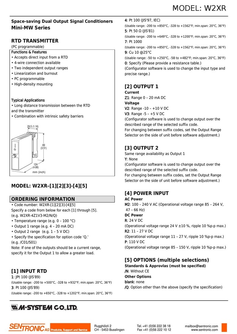
M-system M6SCTC User manual

M6SCTC
P. 1 / 4EM-7972 Rev.4
5-2-55, Minamitsumori, Nishinari-ku, Osaka 557-0063 JAPAN
Phone: +81(6)6659-8201 Fax: +81(6)6659-8510 E-mail: info@m-system.co.jp
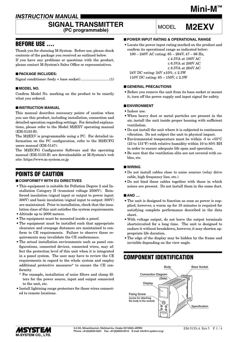
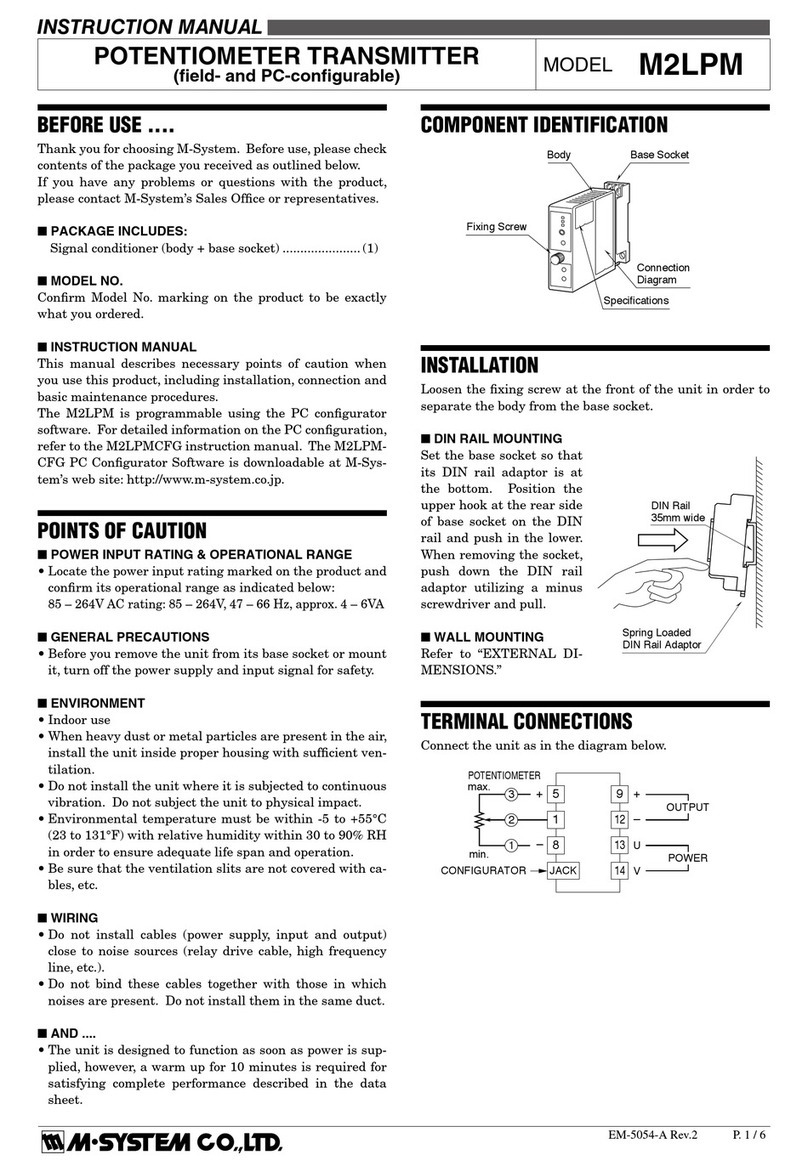
■WIRING
•Do not install cables close to noise sources (relay drive
cable,highfrequencyline,etc.).
•Do not bind these cables together with those in which
noisesarepresent.Donotinstalltheminthesameduct.
■AND ....
The unit is designed to function as soon as power is sup-
plied,however,awarmupfor10minutesisrequiredforsat-
isfyingcompleteperformancedescribedinthedatasheet.
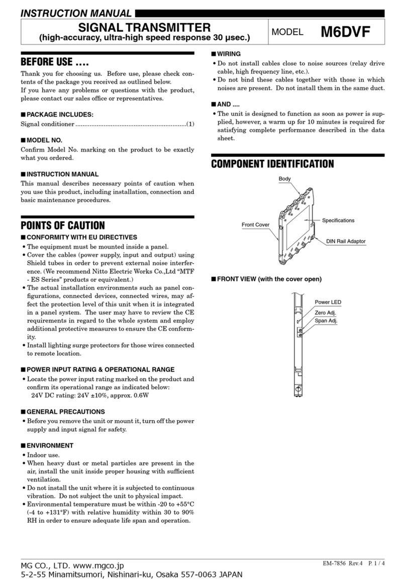
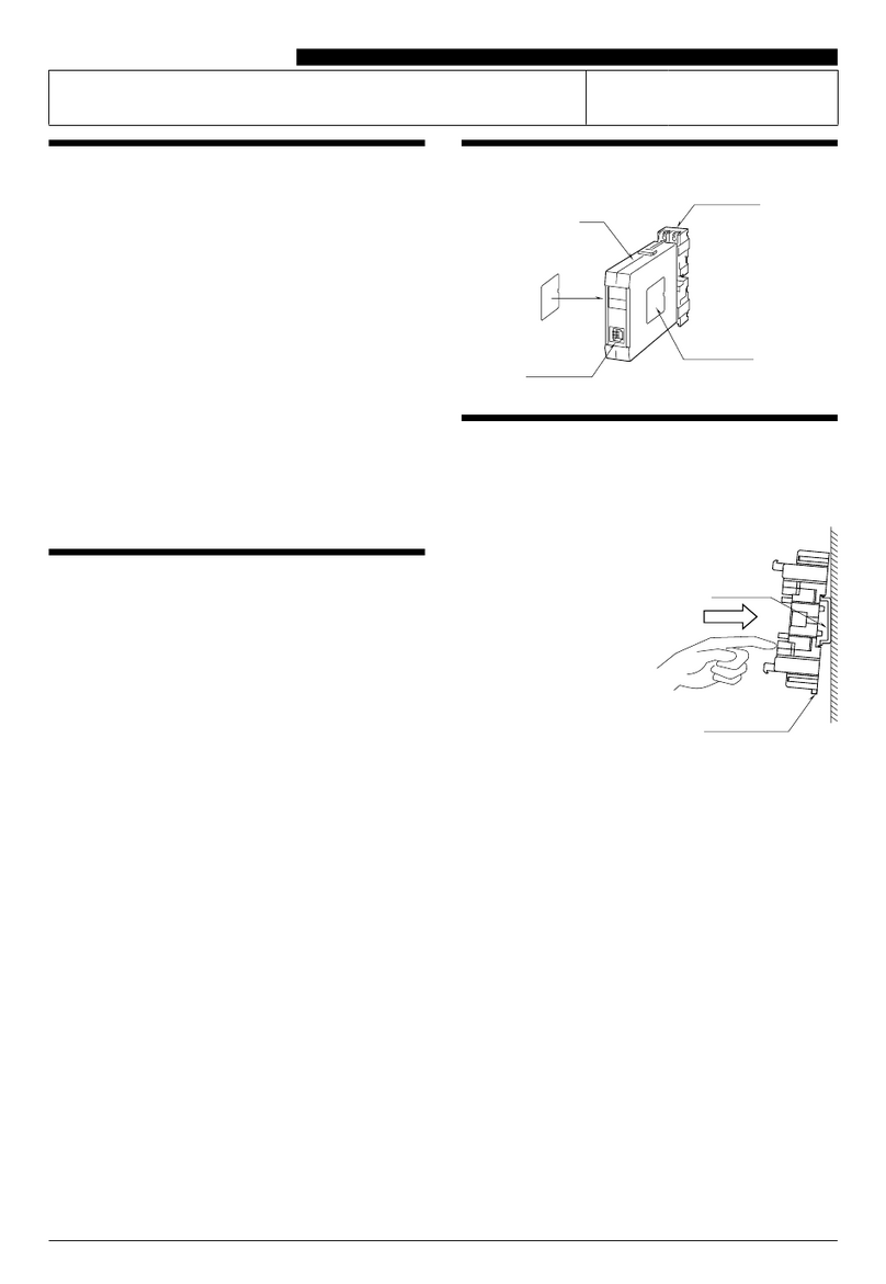
COMPONENT IDENTIFICATION
■FRONT PANEL CONFIGURATION (with the cover open)
Zero Adj.
Power LED
Span Adj.
CT TRANSMITTER
(clamp-on current sensor) MODEL M6SCTC
INSTRUCTION MANUAL
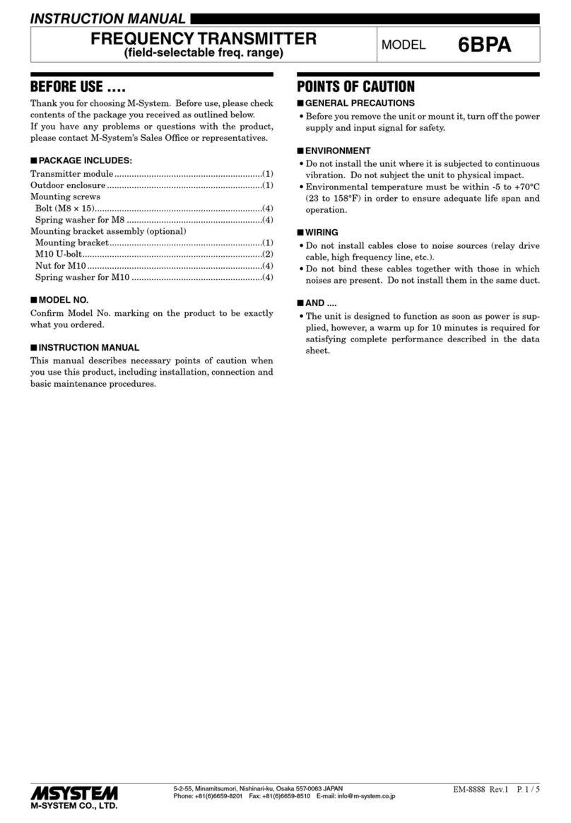
BEFORE USE ....
ThankyouforchoosingM-System.Beforeuse,pleasecheck
contentsofthepackageyoureceivedasoutlinedbelow.
If you have any problems or questions with the product,
pleasecontactM-System’sSalesOfceorrepresentatives.
■PACKAGE INCLUDES:
 Signalconditioner......................................................... (1)
■MODEL NO.
Conrm Model No. marking on the product to be exactly
whatyouordered.
■INSTRUCTION MANUAL
This manual describes necessary points of caution when
youusethisproduct,includinginstallation,connectionand
basicmaintenanceprocedures.
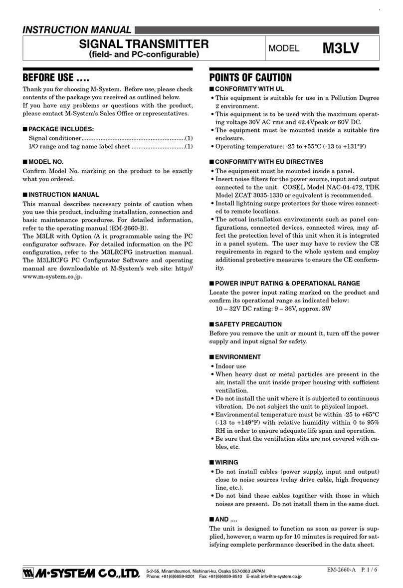
POINTS OF CAUTION
■CONFORMITY WITH EU DIRECTIVES
•Theequipmentmustbemountedinsideapanel.
•UsethecurrentsensorwithM-System’sCLSE-x/CE.
•Theactualinstallationenvironmentssuchaspanelcon-
gurations, connected devices, connected wires, may af-
fecttheprotectionlevelofthisunitwhenitisintegrated
inapanelsystem.TheusermayhavetoreviewtheCE
requirementsinregardtothewholesystemandemploy
additionalprotectivemeasurestoensuretheCEconform-
ity.
■POWER INPUT RATING & OPERATIONAL RANGE
Locatethepowerinputratingmarkedontheproductand
conrmitsoperationalrangeasindicatedbelow:
 24VDCrating:24V±10%,approx.0.5W
■GENERAL PRECAUTIONS
Beforeyouremovetheunitormountit,turnoffthepower
supplyandinputsignalforsafety.
■ENVIRONMENT
•Indooruse
•Whenheavydustormetalparticlesarepresentintheair,
installtheunitinsideproperhousingwithsufcientven-
tilation.
•Donotinstalltheunitwhereitissubjectedtocontinuous
vibration.Donotsubjecttheunittophysicalimpact.
•Environmentaltemperaturemustbewithin-20to+55°C
(-4to+131°F)withrelativehumiditywithin30to90%RH
inordertoensureadequatelifespanandoperation.
■CLAMP-ON CURRENT SENSOR
•Thecurrentsensoristobeorderedseparately.
•Over-voltageclampelementincaseofanopencircuitis
incorporatedforsafety.
•Fixthesensormoduleattheinputcablewithabinding
strap.
Body
Front Cover
DIN Rail Adaptor
Spec. Marking
M6SCTC
P. 2 / 4EM-7972 Rev.4
5-2-55, Minamitsumori, Nishinari-ku, Osaka 557-0063 JAPAN
Phone: +81(6)6659-8201 Fax: +81(6)6659-8510 E-mail: info@m-system.co.jp
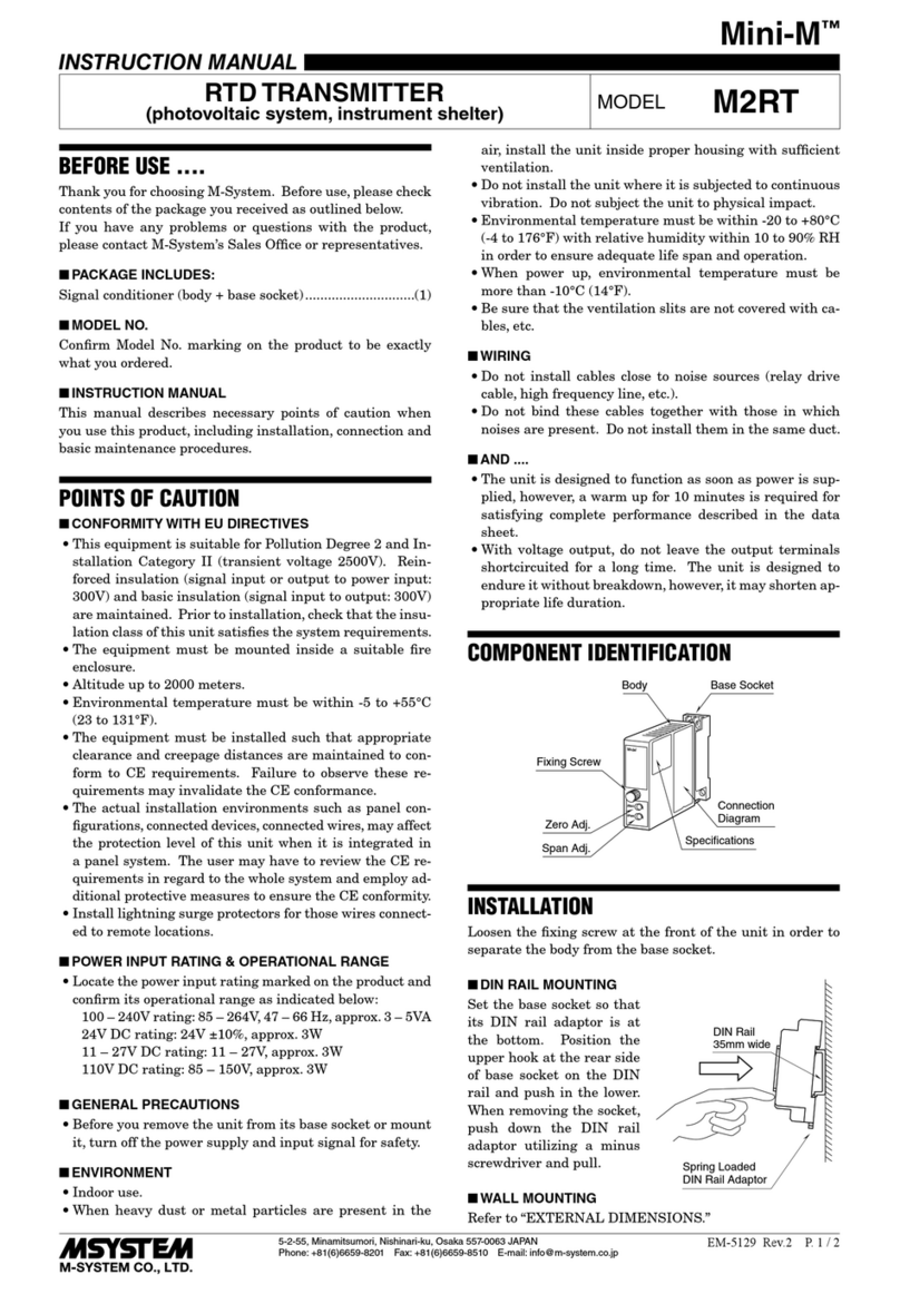
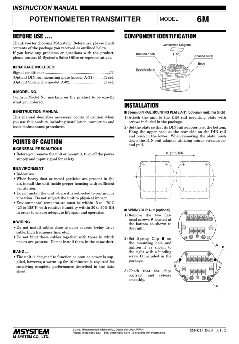
SettheunitsothatitsDINrailadapterisatthebottom.
Whenthe unitis installedto anInstallation Base(model
M6SBS),refertoitsinstructionmanual.

■MOUNTING THE UNIT ON A DIN RAIL
A)HangtheupperhookattherearsideofunitontheDIN
rail.
B)Push in the lower in keeping pressing the unit to the
DINrail.
■REMOVING THE UNIT
A)Pull down the DIN rail adaptor using a minus screw-
driver.
B)Pulloutthelowerpartoftheunit.
C)RemovetheupperpartfromtheDINrail.
TERMINAL CONNECTIONS
Connecttheunitasinthefollowingdiagramorrefertotheconnectiondiagramonthesideoftheunit.
■EXTERNAL DIMENSIONS unit: mm (inch)
ADIN Rail
B
A
DIN Rail Adaptor
CB
INSTALLATION
94 (3.70)
5.9 (.23)
DIN RAIL
35mm wide
DIN RAIL HOOK
*Use a minus screwdriver: tip width 3.8 mm max., tip thickness 0.5 to 0.6 mm
102 (4.02)
[0.5 (.02)]
SCREWDRIVER
INSERTION ANGLE
: approx. 40°
WIRE INSERTION ANGLE
: approx.35°
TEST PROBE
max. 2 (.08) dia.
SCREWDRIVER
*
INSERTION ANGLE
: approx. 35°
5678
1234
• When mounting, no extra space is needed between units.
M6SCTC
P. 3 / 4EM-7972 Rev.4
5-2-55, Minamitsumori, Nishinari-ku, Osaka 557-0063 JAPAN
Phone: +81(6)6659-8201 Fax: +81(6)6659-8510 E-mail: info@m-system.co.jp
■CONNECTION DIAGRAM
■WIRING INSTRUCTIONS
 •Applicablewiresize
  Solid: 0.2to2.5mm2(0.55to1.75dia.)
  Stranded: 0.2to2.5mm2(Tinningwireendsmay
    causecontactfailureandthereforeisnot
    recommended.)
  Ferruled: 0.2to1.5mm2(0.55to1.35dia.)
 •Exposewireconductorsby8mm(0.31”).
How to Connect Wires
Expose 8 mm
1) Insertaminusscrewdriverintothewireentryopening,
betweentheclampandthehousing,untilitstiphitsthe
bottomwhereitisrmlyheld.
2) Insertawire.Pushthescrewdrivertowardthedirection
indicatedwiththearrowinthegurebelowtowidenthe
openingifnecessary.
3) Conrmthat thewire tiphits the bottomandpull out
thescrewdriverinholdingitinposition.
 Conrmthatthewire’sinsulationtubeisnotcaughtin
theclamp.
Screwdriver
Wire
Tension Clamp
Screwdriver
Wire Entry
Wire
+
–
+
–
OUTPUT
5
6
7
8
1
2
POWER
LOAD
SOURCE
CONNECTOR
POWER
k
l
CLAMP-ON SENSOR
M6SCTC
P. 4 / 4EM-7972 Rev.4
5-2-55, Minamitsumori, Nishinari-ku, Osaka 557-0063 JAPAN
Phone: +81(6)6659-8201 Fax: +81(6)6659-8510 E-mail: info@m-system.co.jp
CHECKING
1) Terminalwiring:Checkthatallcablesarecorrectlycon-
nectedaccordingtotheconnectiondiagram.
2) Conrmthatthewireinsulationtubesarenotcaughtin
theclamp.
3) Powerinputvoltage:Checkvoltageacrosstheterminal
7–8withamultimeter.
4) Input:Checkthattheinputsignaliswithin0–100%of
thefull-scale.
5) Output:  Check that the load resistance meets the de-
scribedspecications.
ADJUSTMENT PROCEDURE
This unit is calibrated at the factory to meet the ordered
specications, therefore you usually do not need any cali-
bration.
Formatchingthesignaltoareceivinginstrumentorincase
ofregularcalibration,adjusttheoutputasexplainedinthe
following.
■HOW TO CALIBRATE THE OUTPUT SIGNAL
Useasignalsourceandmeasuringinstrumentsofsufcient
accuracylevel.Turnthepowersupplyonandwarmupfor
morethan10minutes.
1) ZERO:Apply10%inputandadjustoutputto10%.
 Forabidirectionaloutput(e.g.-5–+5VDC),applyan
inputsignalcorrespondingto0VDCoutput.(Samepro-
cedurein(3))
2) SPAN:Apply100%inputandadjustoutputto100%.
3) CheckZEROadjustmentagainwith10%input.
4) When ZERO value is changed, repeat the above proce-
dure1)–3).
MAINTENANCE
Regularcalibrationprocedureisexplainedbelow:
■CALIBRATION
Warmuptheunitforatleast10minutes.Apply5%,25%,
50%, 75% and 100% input signal.  Check that the output
signalfortherespectiveinputsignalremainswithinaccu-
racydescribedinthedatasheet.Whentheoutputisoutof
tolerance, recalibrate the unit according to the“ADJUST-
MENTPROCEDURE”explainedearlier.

Other M-system Transmitter manuals

M-system M5RS User manual

M-system

M-system M5RS User manual

M-system W5PA User manual

M-system

M-system W5PA User manual

M-system JPA2 User manual

M-system

M-system JPA2 User manual

M-system KC User manual

M-system

M-system KC User manual

M-system M3LR User manual

M-system

M-system M3LR User manual

M-system Mini-M M2CA User manual

M-system

M-system Mini-M M2CA User manual

M-system CTS2 User manual

M-system

M-system CTS2 User manual

M-system 17PE User manual

M-system

M-system 17PE User manual

M-system Mini-M M2XT2 User manual

M-system

M-system Mini-M M2XT2 User manual

M-system MXT User manual

M-system

M-system MXT User manual

M-system MXS User manual

M-system

M-system MXS User manual

M-system M6SVS User manual

M-system

M-system M6SVS User manual

M-system 10VF User manual

M-system

M-system 10VF User manual

M-system Mini-M M2AC User manual

M-system

M-system Mini-M M2AC User manual

M-system M6SPA User manual

M-system

M-system M6SPA User manual

M-system W5 Series User manual

M-system

M-system W5 Series User manual

M-system Mini-M M2CEC User manual

M-system

M-system Mini-M M2CEC User manual

M-system Mini-M M2PA User manual

M-system

M-system Mini-M M2PA User manual

M-system 10TG User manual

M-system

M-system 10TG User manual

M-system M6DXU User manual

M-system

M-system M6DXU User manual

M-system VOS2T User manual

M-system

M-system VOS2T User manual

M-system M5CT-5AM User manual

M-system

M-system M5CT-5AM User manual

M-system M5CT User manual

M-system

M-system M5CT User manual

M-system M5XREB User manual

M-system

M-system M5XREB User manual

Popular Transmitter manuals by other brands

Burkert 8026 operating instructions

Burkert

Burkert 8026 operating instructions

United Electronic Industries DNA 429-512 user manual

United Electronic Industries

United Electronic Industries DNA 429-512 user manual

Plasma Sonics OM-1 Operation manual

Plasma Sonics

Plasma Sonics OM-1 Operation manual

DoorHan WDKIT quick start guide

DoorHan

DoorHan WDKIT quick start guide

Servonaut AIR4 manual

Servonaut

Servonaut AIR4 manual

Jung ZLLHS4-01 operating instructions

Jung

Jung ZLLHS4-01 operating instructions

Canon Wireless File Transmitter WFT-E7A instruction manual

Canon

Canon Wireless File Transmitter WFT-E7A instruction manual

RKI Instruments 65-2340RK Operator's manual

RKI Instruments

RKI Instruments 65-2340RK Operator's manual

Manta FMT005 user manual

Manta

Manta FMT005 user manual

Manta FMT004 user manual

Manta

Manta FMT004 user manual

Sony TMR-RF930 Service manual

Sony

Sony TMR-RF930 Service manual

Xantech HDTXSG01 installation instructions

Xantech

Xantech HDTXSG01 installation instructions

Lectrosonics UH110 Operating instructions and troubleshooting guide

Lectrosonics

Lectrosonics UH110 Operating instructions and troubleshooting guide

SUCO 0645 Series Operation instructions

SUCO

SUCO 0645 Series Operation instructions

PR electronics PRetrans 5131 manual

PR electronics

PR electronics PRetrans 5131 manual

Walkera WK-2403 user manual

Walkera

Walkera WK-2403 user manual

PX WTR-3000 manual

PX

PX WTR-3000 manual

TowiTek 2564483 operating instructions

TowiTek

TowiTek 2564483 operating instructions

manuals.online logo
manuals.online logoBrands
  • About & Mission
  • Contact us
  • Privacy Policy
  • Terms and Conditions

Copyright 2025 Manuals.Online. All Rights Reserved.